 Products Home / Lasers / Coherent Sources / Fiber-Coupled Laser Sources / Single Channel Benchtop Sources / Fiber-Coupled Laser Sources: NIR, Distributed Feedback, with TEC
Fiber-Coupled Laser Sources: NIR, Distributed Feedback, with TEC
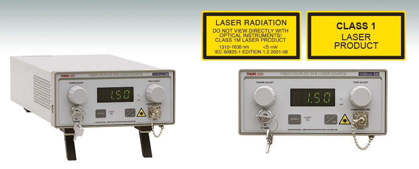
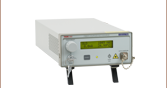
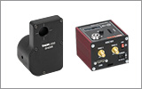
Front Panel Display Provides an Enable Button, Laser Power Control, Display Screen and Temperature Control
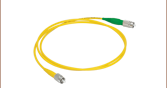
- FC/PC Interface for Single Mode Fiber
- Available Wavelengths: 1310 nm and 1550 nm
- Stable Output with Temperature Control
- Built-In 40 dB Optical Isolator
S3FC1310
1310 nm, 1.5 mW


Please Wait
| Single Channel Benchtop Laser Sources Selection Guide | |||||
|---|---|---|---|---|---|
| Spectrum | Wavelength | TEC | Laser Type | Cavity Type | Output Fiber Type |
| Visible | 405 - 675 nm | No | Semiconductor | Fabry Perot | SM, MM, or PM |
| 405 - 685 nm | Yes | Semiconductor | Fabry Perot | SM | |
| NIR | 785 - 1550 nm | No | Semiconductor | Fabry Perot | SM or PM |
| 705 - 2000 nm | Yes | Semiconductor | Fabry Perot | SM | |
| 1310 - 1550 nm | Yes | Semiconductor | DFB | SM | |
| 1900 - 2000 nm | N/A | Fiber Laser | Fabry Perot | SM | |
| MIR | 2.7 µm | N/A | Fiber Laser | Fabry Perot | SM |
| Other Fiber-Coupled Laser Sources | |||||
Features
- Available Wavelengths: 1310 nm and 1550 nm
- Single Mode, FC/PC Fiber Interface
- Narrow Spectral Linewidths: Typically <0.06 nm
- Thermoelectric Cooler (TEC) for Temperature Stabilization to within 0.005 °C
- Built-in 40 dB Optical Isolator
- Adjustable Temperature Setpoint
- Power Level is Adjustable via Knob and BNC Modulation Input
- Interlock Circuit Provided via 2.5 mm Mono Jack
These Fiber-Coupled Laser Sources feature a narrow linewidth DFB laser diode and a 40 dB optical isolator to eliminate back reflections and frequency jitter. The S3FC Series incorporates an integrated temperature control system for increased wavelength and power stability. The diode temperature and output power can be adjusted using the two front panel adjustment knobs, which ensures that the DFB laser diode can be tuned to match the laser cavity (see the Tuning tab).
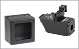
Also found on the front panel is a display that shows the output power in mW or the temperature in °C, an on/off key, an enable button, and the FC/PC bulkhead connector (wide and narrow key compatible). The back panel includes an input that allows the laser diode drive current to be controlled via an external voltage source and a remote interlock input.
Please refer to the table to the right for all of our single channel benchtop laser sources.
Note: The laser must be off when connecting or disconnecting fibers from the device, particularly for power levels above 10 mW. For telecom applications that require tunable output, please see our Benchtop Tunable Telecom Laser Sources.
| Item # | S3FC1310 | S3FC1550 | |
|---|---|---|---|
| Wavelength | Minimum | 1290 nm | 1530 nm |
| Typical | 1310 nm | 1550 nm | |
| Maximum | 1330 nm | 1570 nm | |
| Spectruma |  |
 |
|
| Full Output Power | Minimum | 1.5 mW | |
| Typical | 2.0 mW | ||
| Laser Class | 1M | ||
| Power Stability | 15 min: ±0.05 dB, 24 hr:± 0.1 dB (After 1 hr Warm-up at 25 ± 10 °C Ambient) |
||
| Display Accuracy (mW) | ±10% of Actual | ||
| Setpoint Resolution | 0.01 mW | ||
| Adjustment Range | ~0 mW to Full Power | ||
| TEC | |||
| Stability | 0.005 °C / 1 °C | ||
| Setpoint Accuracy | ±0.25 °C | ||
| Setpoint Resolution | ±0.1 °C | ||
| Adjustment Range | 20 ± 1 °C to 30 ± 1 °C | ||
| Environmental | |||
| Operating Temperature | 15 to 35 °C | ||
| Storage Temperature | 0 to 50 °C | ||
| AC Input | 115/230 VAC (Switch Selectable) 50 - 60 Hz | ||
| Modulation Input | 0 - 5 V = 0 - Full Power, DC or Sinewave Input Only | ||
| Modulation Bandwidth | 5 kHz Full Depth of Modulation 30 kHz Small Signal Modulation |
||
| Fiber | SMF-28e+ | ||
| Output Fiber Connector | FC/PC, Wide Key Compatible | ||
Modulation In
BNC Female
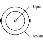
0 to 5 V Max, 50 Ω
Remote Interlock Input
2.5 mm Mono Phono Jack

Terminals must be shorted either by included plug or user device, i.e. external switch, for laser mode "ON" to be enabled.
These benchtop laser sources provide the ability to control not only the output power of the fiber coupled laser diode, but also allows for the precise control of the temperature at which the laser is operating. These two controls can be used to tune the fiber coupled laser diode to an optimum operating point, providing as stable an output as possible. The following graphs are from an OSA monitoring the output of a typical S3FC1550 laser.

The plots above show the effect of changing the operating current of the laser while maintaining a fixed operating temperature (in this case 24.5 °C). The first plot corresponds to a drive current of 75%. Notice the broad line width, the laser is not optimized but the output will appear to be stable. The next plot is at 80%. The laser is approaching a stable point but the second mode indicates the laser is not yet stable. The laser will randomly mode hop, shifting the power from one peak to another resulting in erratic performance and power output. In the third plot, the current is at 85% and shows a typical optimized DFB output: a single, very narrow line width and very stable power. The last two plots, taken at 90% and 95%, show the laser passing through the optimum point and starting to ebb again.
The plots below show the relationship of temperature verse stability. With the drive current fixed at 85% of maximum, the operating temperature was increased by 0.1°C per plot, starting at 24.3 °C. In the first plot, the laser appears stable but it can be improved. As the temperature is increased to 24.4 °C the laser enters a transition point between modes. At this temperature, the laser may mode hop resulting in erratic output. At 24.5 °C the laser has reached a stable operating point, indicated by the single narrow line width. The last two plots (24.7 °C and 24.9 °C) show the laser passing through the optimum point and decreasing in stability and desired output.


The examples above demonstrate the need to adjust the drive current and/or temperature of the laser diode in order to tune the output of the laser diode so that the output wavelength of the DFB laser diode matches laser cavity. There are multiple settings that will lase stably, and by varying one or both the lasing wavelength of the laser can be tuned over a narrow wavelength range.
Laser Safety and Classification
Safe practices and proper usage of safety equipment should be taken into consideration when operating lasers. The eye is susceptible to injury, even from very low levels of laser light. Thorlabs offers a range of laser safety accessories that can be used to reduce the risk of accidents or injuries. Laser emission in the visible and near infrared spectral ranges has the greatest potential for retinal injury, as the cornea and lens are transparent to those wavelengths, and the lens can focus the laser energy onto the retina.
 |
 |
 |
 |
 |
 |
 |
 |
 |
Safe Practices and Light Safety Accessories
- Laser safety eyewear must be worn whenever working with Class 3 or 4 lasers.
- Regardless of laser class, Thorlabs recommends the use of laser safety eyewear whenever working with laser beams with non-negligible powers, since metallic tools such as screwdrivers can accidentally redirect a beam.
- Laser goggles designed for specific wavelengths should be clearly available near laser setups to protect the wearer from unintentional laser reflections.
- Goggles are marked with the wavelength range over which protection is afforded and the minimum optical density within that range.
- Laser Safety Curtains and Laser Safety Fabric shield other parts of the lab from high energy lasers.
- Blackout Materials can prevent direct or reflected light from leaving the experimental setup area.
- Thorlabs' Enclosure Systems can be used to contain optical setups to isolate or minimize laser hazards.
- A fiber-pigtailed laser should always be turned off before connecting it to or disconnecting it from another fiber, especially when the laser is at power levels above 10 mW.
- All beams should be terminated at the edge of the table, and laboratory doors should be closed whenever a laser is in use.
- Do not place laser beams at eye level.
- Carry out experiments on an optical table such that all laser beams travel horizontally.
- Remove unnecessary reflective items such as reflective jewelry (e.g., rings, watches, etc.) while working near the beam path.
- Be aware that lenses and other optical devices may reflect a portion of the incident beam from the front or rear surface.
- Operate a laser at the minimum power necessary for any operation.
- If possible, reduce the output power of a laser during alignment procedures.
- Use beam shutters and filters to reduce the beam power.
- Post appropriate warning signs or labels near laser setups or rooms.
- Use a laser sign with a lightbox if operating Class 3R or 4 lasers (i.e., lasers requiring the use of a safety interlock).
- Do not use Laser Viewing Cards in place of a proper Beam Trap.
Laser Classification
Lasers are categorized into different classes according to their ability to cause eye and other damage. The International Electrotechnical Commission (IEC) is a global organization that prepares and publishes international standards for all electrical, electronic, and related technologies. The IEC document 60825-1 outlines the safety of laser products. A description of each class of laser is given below:
| Class | Description | Warning Label |
|---|---|---|
| 1 | This class of laser is safe under all conditions of normal use, including use with optical instruments for intrabeam viewing. Lasers in this class do not emit radiation at levels that may cause injury during normal operation, and therefore the maximum permissible exposure (MPE) cannot be exceeded. Class 1 lasers can also include enclosed, high-power lasers where exposure to the radiation is not possible without opening or shutting down the laser. |  |
| 1M | Class 1M lasers are safe except when used in conjunction with optical components such as telescopes and microscopes. Lasers belonging to this class emit large-diameter or divergent beams, and the MPE cannot normally be exceeded unless focusing or imaging optics are used to narrow the beam. However, if the beam is refocused, the hazard may be increased and the class may be changed accordingly. |  |
| 2 | Class 2 lasers, which are limited to 1 mW of visible continuous-wave radiation, are safe because the blink reflex will limit the exposure in the eye to 0.25 seconds. This category only applies to visible radiation (400 - 700 nm). |  |
| 2M | Because of the blink reflex, this class of laser is classified as safe as long as the beam is not viewed through optical instruments. This laser class also applies to larger-diameter or diverging laser beams. |  |
| 3R | Class 3R lasers produce visible and invisible light that is hazardous under direct and specular-reflection viewing conditions. Eye injuries may occur if you directly view the beam, especially when using optical instruments. Lasers in this class are considered safe as long as they are handled with restricted beam viewing. The MPE can be exceeded with this class of laser; however, this presents a low risk level to injury. Visible, continuous-wave lasers in this class are limited to 5 mW of output power. |  |
| 3B | Class 3B lasers are hazardous to the eye if exposed directly. Diffuse reflections are usually not harmful, but may be when using higher-power Class 3B lasers. Safe handling of devices in this class includes wearing protective eyewear where direct viewing of the laser beam may occur. Lasers of this class must be equipped with a key switch and a safety interlock; moreover, laser safety signs should be used, such that the laser cannot be used without the safety light turning on. Laser products with power output near the upper range of Class 3B may also cause skin burns. |  |
| 4 | This class of laser may cause damage to the skin, and also to the eye, even from the viewing of diffuse reflections. These hazards may also apply to indirect or non-specular reflections of the beam, even from apparently matte surfaces. Great care must be taken when handling these lasers. They also represent a fire risk, because they may ignite combustible material. Class 4 lasers must be equipped with a key switch and a safety interlock. |  |
| All class 2 lasers (and higher) must display, in addition to the corresponding sign above, this triangular warning sign. |  |
|
| Posted Comments: | |
Wan Zo
(posted 2022-11-24 18:29:30.367) I bought S3FC1550 a few month ago (serial number is TP02857539-25596, manufacture date is 07/21/2022).
I turned key clockwise to operate laser, but laser did not work. display in front panel did not light up and air pan in rear panel did not work also.
I checked line select switch (in south korea, voltage is 220V, so I set it to 220V) and fuse (fuse is unbroken).
Could you help me? I couldn't find any troubleshooting in laser manuel.
Warm Regards,
Wan. ksosnowski
(posted 2022-12-09 01:53:04.0) Hello Wan, thanks for reaching out to Thorlabs, and sorry for the issues you're experiencing with this S3FC laser. The unit ships with the 250mA fuse installed for 115VAC regions. Operating at 220VAC would require a lower current fuse as the higher voltage otherwise could allow too high of power draw at the same current level. This could potentially damage the unit's internal power supply, though in this scenario the fuse itself would remain unharmed. The S3FC manual covers the fuse selection on pages 4/5, and I have reached out directly to discuss your issues in more detail. For issues like this, we also recommend reaching out to techsupport@thorlabs.com or your local tech support team directly. Erick Ulin Avila
(posted 2020-01-23 13:27:20.623) what is the size of the whole system. I need its dimensions please. Thanks in advance asundararaj
(posted 2020-01-23 03:40:24.0) Thank you for contacting Thorlabs. The outer dimension of the benchtop unit is about 12.49" x 5.76" x 3.06" and can be found in our AutoCAD document for the product - https://www.thorlabs.com/_sd.cfm?fileName=19146-E0W.pdf&partNumber=S3FC1310 Muhammad Adeel
(posted 2019-09-16 19:22:12.787) Dear Representative,
It is apprised that I want to purchase a laser source and an optical modulator for setting up a Phase-OTDR system. For this I need a laser source with a very narrow linewidth (Typically less than 5KHz) and frequency drift. The optical modulator must support 1 to 10GHz frequency of the injected pulses for the same Phase-OTDR system. Kindly help me in selecting the appropriate devices (Laser source with optical modulator).
Thank you very much. YLohia
(posted 2019-09-16 03:03:48.0) Hello, thank you for contacting Thorlabs. We currently offer the SFL1550P modulator with a narrow linewidth. We are also currently working on releasing an ultra low linewidth laser (< 100 Hz). We offer various phase modulators capable of handling those frequencies (LN53S-FC and LN65S-FC). I Have reached out to you directly to discuss your application further. 大希 氏原
(posted 2019-07-19 10:59:48.53) 1点質問がございます。
「狭いスペクトル線幅: <0.06 nm(典型値)」とありますが、@-20 dB等、どの区間を指しているのでしょうか。
よろしくお願いいたします。 YLohia
(posted 2019-07-19 08:57:11.0) Hello, thank you for contacting Thorlabs. This specification refers to the -20 dB designation. |