 Products Home / Optomechanical Components / Optical Cage Systems / 30 mm Cage Components / 30 mm Cage System Optic Mounts / Cylindrical Lens Mount for 30 mm Cage Systems
Cylindrical Lens Mount for 30 mm Cage Systems
- Mount Cylindrical Lenses or Other Rectangular
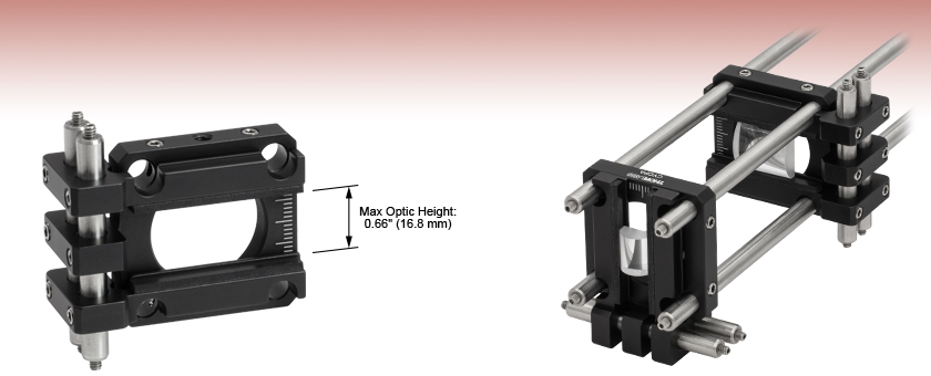
Optics in 30 mm Cage Systems - Maximum Optic Height of 0.66" (16.8 mm)
- Engraved Graduations at 1 mm Spacings
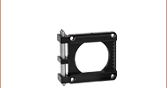
CYCPA
Application Idea
Two Cylindrical Lenses
Oriented Perpendicular
to Each Other Correct
Astigmatism in an Image


Please Wait
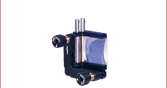
This animation depicts various mounting options of the CYCPA
Cylindrical Lens Mount.
Features
- Rectangular Optic Mount for 30 mm Cage Systems
- Two Manually Positioned Arms Hold Optics up to 0.66" (16.8 mm) Tall Within the Cage System
- Mounting Arms and Cage Plate can be Moved Independently (See Animation at Right)
- Graduations at 1 mm Intervals Help with Centration and Repeatability
- Internal SM1 (1.035"-40) Threads Compatible with Ø1" Lens Tubes
- One 8-32 (M4 x 0.7) Tapped Hole for Post Mounting
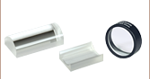
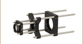
Thorlabs' Cylindrical Lens Mount for 30 mm Cage Systems is designed to orient a cylindrical lens or another rectangular optic horizontally or vertically within a 30 mm cage system. The lens is effectively clamped between the two sliding arms, each of which is lined with a 1.51" (38.3 mm) long rubber pad and has a lip for resting the plano side of the lens against, as shown by the photo at the top of the page. The manually positioned arms can hold optics from 0.16" to 0.66" tall (4.0 mm to 16.8 mm) before the arms begin to obscure the through holes for the cage system. The included 2" long cage rods can be replaced with longer cage rods (sold separately) to accommodate taller optics, but the mount cannot be used within a cage system if the arms or the optic overlap with the through holes.
The arms and the cage plate are secured to the side-mounted 2" long cage rods (Item # ER2) using M4 locking setscrews that accept a 5/64" (2.0 mm) hex key. The cage plate and arms can be moved and locked independently. Hence, by loosening the cage plate while keeping the arms tightened, the user may translate a lens parallel to the cage rods (i.e., in a transverse direction) without disturbing the rest of the cage system. The arms can also be relocated from the front of the cage plate to the back of the cage plate.
Both sides of the cage plate are engraved with tick marks; the major ticks occur every 5 mm, the minor ticks occur every 1 mm, and the pattern spans a total length of 20 mm. To help center the mounted optic, a major tick is placed at the center line of the plate. It is easiest to center the cylindrical lens when the cylindrical axis is parallel to the arms, as demonstrated in the Application Idea at the top of the page.
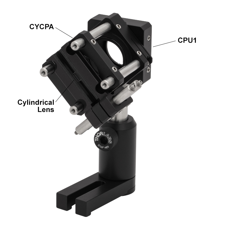
Four M4 setscrews, which accept 5/64" (2.0 mm) hex keys, secure the cage plate within a 30 mm cage system. The central bore is internally SM1 threaded (1.035"-40), making it compatible with our Ø1" lens tubes and SM1-mounted optics. The plate also contains an 8-32 (M4 x 0.7) tapped hole for mounting on a Ø1/2" post. Please note that an attached post can mechanically clash with the bottom arm if the arm has been moved down too far. By pairing this mount with our CPU1 Rotating Cage Segment Plate, a cylindrical lens can be rotated within a 30 mm cage system (see the Application Idea tab for details).
Thorlabs also manufactures Kinematic Mirror Mounts for Rectangular Optics, which offer tip and tilt adjustments, and a Cylindrical Lens Mount for 60 mm Cage Systems that directly supports optics as tall as 1.84" (46.8 mm).
Application Idea
By pairing the CYCPA(/M) Cage Mount with our CPU1(/M) Rotating Cage Segment Plate, it is possible to rotate a cylindrical lens about the optical axis defined by a 30 mm cage system (see image below). The following tables correspond to either the imperial or metric list of items used in this assembly.
| Posted Comments: | |
| No Comments Posted |