Right-Angle Kinematic Mirror Mounts for 30 mm Cage Systems
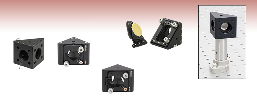
- 30 mm Cage System Compatible
- Mount Ø1/2" Parabolic or Ø1" Circular, Elliptical, or Parabolic Optics
- Post Mountable
KCB1C
Holds Ø1" (Ø25.4 mm) Optics
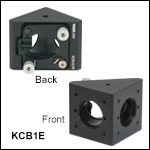
KCB1E
Holds 1" Elliptical Optics
Application Idea
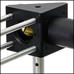
Using an RBP1 Pin-Aligned, Clamping Post Base and KCB1 Mount to Align a Laser Above the Holes in an Optical Table
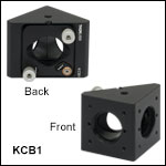
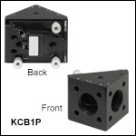
Front
Back
SM1-Threaded
Hole
KCB1P
Holds Ø1" (Ø25.4 mm) Off‑Axis Parabolic Mirrors

Please Wait
Click to Enlarge
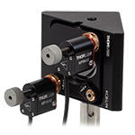
Figure 1.1 A 30 mm Cage Right-Angle Kinematic Mount can be Motorized with Two MPIA10 Actuators
| Alternative Size Options |
|---|
| 16 mm Kinematic Cage Mounts |
| 30 mm Kinematic Cage Mounts |
| 30 mm Right-Angle Kinematic Cage Mounts |
| 60 mm Kinematic Cage Mounts |
Features
- Turning Mirror Mounts for Ø1/2" Off-Axis Parabolic Optics or Ø1" Round, Elliptical, or Off-Axis Parabolic Optics
- Compatible with 30 mm Cage System
- ±4° Kinematic Tip and Tilt Adjustment
- Use RBP1(/M) Pin-Aligned, Clamping Post Base with KCB1 Series Mirror Mounts (Except Item # KCB1P(/M)) to Simplify Beam Alignment Over the Threaded Holes in an Optical Table
Thorlabs' Right-Angle Kinematic Mounts are designed for easy integration into our 30 mm cage system. Refer to Table 1.2 for a summary of the mounts offered on this page.
All of these mounts have SM1-threaded bores on the entrance and exit ports for Ø1" lens tube integration. Each mount has three 3/16"-100 adjusters, allowing for precise alignment of the mirror and accurate alignment of the beam path within a 30 mm cage system. Each adjuster screw has a thread pitch of 100 TPI (Threads per Inch), which allows for smooth, high-resolution movement of 0.01" (0.254 mm) per rotation. The faces of each mount have mounting features for compatibility with our 30 mm cage system, as specified in Table 1.2. Tapped holes allow ER cage rods to thread directly into the mount, while mounts with smooth bore holes secured the cage rods using setscrews.
Thorlabs' cage system provides a convenient way to construct large optomechanical systems with an established line of precision-machined building blocks designed for high flexibility and accurate alignment. Our mounts featured here have been designed to allow for the precise angular positioning of optics within a cage system. Thorlabs offers 16 mm, 30 mm, and 60 mm cage systems designed for Ø1/2", Ø1", and Ø2" optical components, respectively. The parts on this page are compatible with our 30 mm cage system and utilize Ø6 mm ER cage rods.
The RBP1(/M) Pin-Aligned, Clamping Post Base, available below, is designed to align the surface of a mirror mounted in a KCB1(/M), KCB1C(/M), KCB1E(/M), KCB1EC(/M) or KCB1P5(/M) Right-Angle Kinematic Mirror Mount above a hole in the optical table, simplifying the process of aligning a reflected laser beam over the table's threaded holes. To use this clamping base, the KCB1 series mount must be attached to a Ø1" or Ø25 mm Pillar Post.
| Table 1.2 Overview of 30 mm Right-Angle Kinematic Cage Mounts | ||||||
|---|---|---|---|---|---|---|
| Item # | KCB1(/M) | KCB1C(/M) | KCB1E(/M) | KCB1EC(/M) | KCB1P5(/M) | KCB1P(/M) |
| Product Photo (Click to Enlarge) |
 |
 |
 |
 |
 |
 |
| Compatible Optics | Ø1" (Ø25.4 mm) Round Optics | 1" (25.4 mm) Elliptical Optics | Ø1/2" (Ø12.7 mm) Off-Axis Parabolic Mirrors | Ø1" (Ø25.4 mm) Off-Axis Parabolic Mirrors |
||
| Sample Optic Photo |  |
 |
 |
 |
||
| Cage Rod Features | Tapped Holes | Smooth Bore Holes | Tapped Holes | Smooth Bore Holes | Smooth Bore Holes | Smooth Bore Holes |
| Post Mounting | One 8-32 (M4) Tap & One 1/4"-20 (M6) Tap | Two 1/4"-20 (M6) Taps | ||||
Cage System Overview
The Cage Assembly System provides a convenient way to construct large optomechanical systems with an established line of precision-machined building blocks designed for high flexibility and accurate alignment.
16 mm, 30 mm, and 60 mm Cage System Standards
Thorlabs offers three standards defined by the center-to-center spacing of the cage assembly rods (see Figure 14A). The 16 mm cage, 30 mm cage, and 60 mm cage standards are designed to accommodate Ø1/2", Ø1", and Ø2" optics, respectively. Specialized cage plates that allow smaller optics to be directly inserted into our larger cage systems are also available.
Standard Threads
The flexibility of our Cage Assembly System stems from well-defined mounting and thread standards designed to directly interface with a wide range of specialized products. The three most prevalent thread standards are our SM05 Series (0.535"-40 thread), SM1 Series (1.035"-40 thread), and SM2 Series (2.035"-40 thread), all of which were defined to house the industry's most common optic sizes. Essential building blocks, such as our popular lens tubes, directly interface to these standards.

Figure 14A An example of the standard cage plate measurements determining cage system compatibility.
| Standard Cage System Measurements | |||
|---|---|---|---|
| Cage System | 16 mm | 30 mm | 60 mm |
| Thread Series | SM05 | SM1 | SM2 |
| Rod to Rod Spacing | 16 mm (0.63") | 30 mm (1.18") | 60 mm (2.36") |
| Total Length | 25 mm (0.98") | 41 mm (1.60") | 71.1 mm (2.80") |
| Cage Components | ||
|---|---|---|
| Cage Rods | 16 mm | These rods are used to connect cage plates, optic mounts, and other components in the cage system. The SR Series Cage Rods are compatible with our 16 mm cage systems, while the 30 mm and 60 mm cage systems use ER Series Cage Rods. |
| 30 mm | ||
| 60 mm | ||
| Cage Plates | 16 mm | These serve as the basic building blocks for a cage system. They may have SM-threaded central bores, smooth bores sized for industry standard optics or to accommodate the outer profile of our SM Series Lens Tubes, or specialized bores for other components such as our FiberPorts. |
| 30 mm | ||
| 60 mm | ||
| Optic Mounts | 16 mm | Thorlabs offers fixed, kinematic, rotation, and translation mounts specifically designed for our Cage Systems. |
| 30 mm | ||
| 60 mm | ||
| Cage Cubes | 16 mm | These cubes are useful for housing larger optical components, such as prisms or mirrors, or optics that need to sit at an angle to the beam path, such as beamsplitters. Our cage cubes are available empty or with pre-mounted optics. |
| 30 mm | ||
| 60 mm | ||
| Replacement Setscrews | Replacement setscrews are offered for our 16 mm (SS4B013, SS4B025, and SS4B038) and 30 mm (SS4MS5 and SS4MS4) cage systems products. | |
| Post and Breadboard Mounts and Adapters | Mounting options for cage systems can be found on our Cage System Construction pages. Cage Systems can be mounted either parallel or perpendicular to the table surface. | |
| Size Adapters | Cage System Size Adapters can be used to integrate components from different cage system and threading standards. | |
| Specialized Components | Thorlabs also produces specialized cage components, such as Filter Wheels, a HeNe Laser Mount, and a FiberPort Cage Plate Adapter, allowing a wide range of our products to be integrated into cage-mounted optical systems. Explore our Cage Systems Visual Navigation Guide to see the full range of Thorlabs' cage components. | |
| Posted Comments: | |
user
(posted 2024-03-26 14:16:50.213) Two suggestions:
1. Selling the mirror mounting plate separately so it possible to quickly switch out mirrors without buying another whole mount.
2. A version of the mirror mounting plate for 1/2" OAPs. cdolbashian
(posted 2024-03-29 02:03:21.0) Thank you for reaching out to us with this inquiry! These are great suggestions! I have requested such changes internally. Michael Shuldiner
(posted 2023-05-21 16:53:50.477) Hello at Thorlabs
Please advise what piezo activator can be possibly used with KCB1E/M in 30mm stage setting? I do not see actuator compatible with its 3/16"-100 mounting thread.
Is there any adapter for this case? Or is any other 90deg mirror mount in 30mm cage system that can receive piezo actuator?
Regards
Michael Shuldiner
Engineer jdelia
(posted 2023-05-22 01:18:50.0) Thank you for contacting Thorlabs. We unfortunately do not have a way to motorize the KCB1E/M. As you mentioned, this mount uses 3/16"-100 threaded adjusters, and we do not offer any actuators compatible with this threading. At this time, we do not have motorized options for our right-angle cage mounts, but this is certainly something we can look into in the future. Alexander Kuznetsov
(posted 2022-11-14 14:18:34.487) Hi,
I would like to motorize the kinematic mirror mount KCB1C/M. Are there (piezo/motor) actuators that are compatible with KCB1C/M?
If this is not possible, are there plans to introduce such functionality in the future?
Thanks in advance. cdolbashian
(posted 2022-11-16 11:53:12.0) Thank you for reaching out to us with this request. At this time, we do not have motorized actuators which are compatible with our cage elements, though this is certainly something which we are looking to produce in the future. Jackson Berlage
(posted 2022-06-30 10:47:45.32) Dear ThorLabs,
I am interested in potentially mounting a laser directly to the cage rods for the KCB1 or KCB1C, centered and directed at the mirror. Any suggestions for an adapter that would allow me to do this? jdelia
(posted 2022-07-06 01:09:19.0) Thank you for contacting Thorlabs. I have contacted you directly regarding the details of your application. Sang Tae Park
(posted 2021-01-13 19:55:30.24) Dear Thorlabs,
Can you provide RoHS certificates for KCB1/M, SM1A7, SM1D12D, PF10-03-P01, WG11050-A, WG11050-B ?
The link doesn't work for those items.
Best regards, YLohia
(posted 2021-01-14 10:54:14.0) Hello, thank you for contacting Thorlabs. I have reached out to you with the RoHS certifications for these. mmueller
(posted 2018-09-02 19:46:41.987) Hi, is it possible to purchase only the housing, completely without the mirror mount? That would give me access to the path with my own optics and mount (externally). Thank you llamb
(posted 2018-09-04 08:50:11.0) Thank you for contacting Thorlabs. For quotes on custom, special, or component products you may email techsupport@thorlabs.com. In this case, offering the housing only should indeed be feasible. I will reach out to you by email to discuss this possible quote. ehchen
(posted 2016-04-23 12:36:31.88) To follow up on questions by other customers from a year ago, is it now possible to install motorized or piezo actuators on the KCB1 (or similar cage, mount) systems? Thanks, Ed besembeson
(posted 2016-04-25 09:16:26.0) Response from Bweh at Thorlabs USA: It is not possible to install a motorized actuator to the KCB1 at this time. We don't have a suitable motorized actuator with 3/16-100 threads that can be used. Yann.Cesbron
(posted 2016-04-15 10:38:56.163) You seem to have measured the stability of the KCB1 in 2013. Could you share the data?
Also, is the design of the KCB1C/M similar enough (same besides threads/holes?) to allow direct comparison? besembeson
(posted 2016-04-15 04:47:14.0) Response from Bweh at Thorlabs USA: I will contact you regarding the data KCB1 data and yes they are similar enough for direct comparison. jared.bullock
(posted 2015-06-05 18:03:41.967) What is the resolution of the adjustment screws on the KCB1C? jlow
(posted 2015-08-25 11:55:29.0) Response from Jeremy at Thorlabs: The adjustment screws used in the KCB1C is 3/16"-100. Each revolution of the adjustment screw would move it by 0.01" or 0.254mm. user
(posted 2015-05-13 13:37:22.24) What is the path length inside the KCB1? Assuming we are using a typical mirror (e.g., PF10-03-P01)? In other words, if a beam enters perfectly centered, then reflects off the mirror, and exits perfectly centered, what is the distance traveled from entrance to exit? Thanks. cdaly
(posted 2015-05-13 03:05:31.0) Response from Chris at Thorlabs: With the beam traveling along the central axis of the 30mm cage on each side of the KCB1, the mirror would be positioned in such a way that the optical path length through the cube would be 1.90"(48.3mm). n.kad
(posted 2015-05-06 12:31:20.19) Can I use an actuator with these 90 deg cage mounts? cdaly
(posted 2015-05-11 08:53:03.0) Response from Chris at Thorlabs: The kinematic cage cubes are not directly compatible with the motorized actuators as they use 3/16"-100 threaded actuator screws, but it may be possible to offer a custom version with actuators pre-fitted. We will contact you directly to discuss this. achmyro
(posted 2013-12-09 15:28:24.757) Dear Technical support,
Do you have any data about stability of KCB1 mirror mount?
How does it compare to Polaris 1" mirror mount? jlow
(posted 2013-12-19 12:43:16.0) Response from Jeremy at Thorlabs: We do not have data on the comparison but we will measure this and send you the results. |

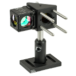
Click to Enlarge Figure G1.1 Beamsplitter Cube Attached to the KCB1 Turning Mirror Using the CM1-CC Cage Cube Connector
- Mounts Ø1" (25.4 mm) Optics at a 45° Angle to the Optical Axis
- Eight 4-40 Tapped Holes for ER Cage Rods
- Provides ±4° Kinematic Tip and Tilt Adjustment
- 30 mm Cage System and SM1 (1.035"-40) Compatible
- Post Mountable:
The KCB1(/M) right-angle mount provides pitch and yaw adjustment for a Ø1" (Ø25.4 mm) optic held in a mounting plate whose nominal horizontal position is at a 45° angle. The ports are equipped with SM1-threaded (1.035"-40) bores. The KCB1(/M) has eight 4-40 tapped holes spaced to mate with our 30 mm cage system standard. ERSCB ER Rod Adapters are necessary to effectively connect, adjust, and lock two of these right angle cage mounts together within the cage system. The kinematic tip and tilt adjustment plate on these cubes is actuated with three 100 TPI (Threads per Inch) adjustment screws that allow for smooth, high-resolution movement of 0.01" (0.254 mm) per turn. Two of these adjusters include removable knobs, while the third must be tuned with a 5/64" (2 mm) hex key or balldriver.
A nylon-tipped setscrew is used to secure Ø1" (25.4 mm) optics using a 5/64" (2 mm) hex key or balldriver via the mounts' rear-loading, double-bored hole. The rear loading design does not limit the maximum thickness of the mounted optic and the mounted optic remains accessible even after the mount is fitted with cage rods or lens tubes. The minimum thickness for optics that can be secured by these mounts is 0.12" (3 mm), and optics thinner than 0.12" (3 mm) will need to be combined with an optic spacer.

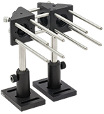
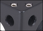
Click to Enlarge Figure G2.2 KCB1C Mount with Smooth Bores (Right) Directly Attached to a KCB1 Mount with Tapped Holes (Left)
Click to Enlarge
Figure G2.1 KCB1C(/M) Mounts have Smooth Bores for Cage Rods
- Mounts Ø1" (25.4 mm) Optics at a 45° Angle to the Optical Axis
- Eight 0.25" (6.35 mm) Deep Smooth Bore Holes for ER Cage Rods
- Provides ±4° Kinematic Tip and Tilt Adjustment
- 30 mm Cage System and SM1 (1.035"-40) Compatible
- Post Mountable:
The KCB1C(/M) right-angle mount provides pitch and yaw adjustment for a Ø1" (Ø25.4 mm) optic held in a mounting plate whose nominal horizontal position is at a 45° angle. The ports are equipped with SM1-threaded (1.035"-40) bores and four 0.25" (6.35 mm) deep smooth bore holes spaced to mate with our 30 mm cage system standard. The cage rods are secured by eight setscrews using a 5/64" (2 mm) hex key or balldriver. This design allows multiple 30 mm cage components to be directly interfaced without the need for ERSCB ER Rod Adapters. The kinematic tip and tilt adjustment plate on these cubes is actuated with three 100 TPI (Threads per Inch) adjustment screws that allow for smooth, high-resolution movement of 0.01" (0.254 mm) per turn. Two of these adjusters include removable knobs, while the third must be tuned with a 5/64" (2 mm) hex key or balldriver.
A nylon-tipped setscrew is used to secure Ø1" (25.4 mm) optics using a 5/64" (2 mm) hex key or balldriver via the mounts' rear-loading, double-bored hole. This hole features a clearance cut that provides a maximum clear aperture for any transmitted light and allows easy access to mounted optics. The rear loading design does not limit the thickness of the mounted optic and the mounted optic remains accessible even after the mount is fitted with cage rods or lens tubes. The minimum thickness for optics that can be secured by these mounts is 0.12" (3 mm), and optics thinner than 0.12" (3 mm) will need to be combined with an optic spacer.

- Mounts 1" (25.4 mm) Elliptical Optics at a 45° Angle to the Optical Axis
- Eight 4-40 Tapped Holes for ER Cage Rods
- Provides ±4° Kinematic Pitch and Yaw Adjustment
- Z-Axis Translation Using All Three Adjusters: ±0.12" (±3.0 mm)
- 30 mm Cage System and SM1 (1.035"-40) Compatible
- Post Mountable:
The KCB1E(/M) right-angle mount provides pitch and yaw adjustment for a 1" (25.4 mm) elliptical optic held in a mounting plate whose nominal horizontal position is at a 45° angle. The ports are equipped with SM1-threaded (1.035"-40) bores and four 4-40 tapped holes center-to-center spaced to mate with our 30 mm Cage System standard. The kinematic pitch and yaw adjustment plate is actuated with 100 TPI (Threads per Inch) adjustment screws that provide angular resolution of 7.6 mrad/rev. Two of these adjusters include removable knobs, while the third must be tuned with a 5/64" (2 mm) hex key or balldriver. While the optic face is nominally centered within the mount, the third adjuster can be used for fine tuning the position along the optical axis.
A nylon-tipped adjustment screw and a nylon-coated spring clip are used to secure 1" (25.4 mm) elliptical optics using a 0.05" (1.3 mm) hex key or balldriver via the mount's rear-loading, double-bored hole. The rear loading design ensures that the optic remains accessible even after the mount is fitted with cage rods or lens tubes. These mounts were designed for a 6 mm thick optic. We offer dielectric and metallic elliptical mirrors, which are compatible with these mounts.


Click to Enlarge
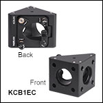
Figure 586A KCB1EC(/M) Mounts have Smooth Bores for Cage Rods
- Mounts 1" (25.4 mm) Elliptical Optics at a 45° Angle to the Optical Axis
- Eight 0.25" (6.35 mm) Deep Smooth Bore Holes for ER Cage Rods
- Provides ±4° Kinematic Pitch and Yaw Adjustment
- Z-Axis Translation Using All Three Adjusters: ±0.12" (±3.0 mm)
- 30 mm Cage System and SM1 (1.035"-40) Compatible
- Post Mountable:
The KCB1EC(/M) right-angle mount provides pitch and yaw adjustment for a 1" (25.4 mm) elliptical optic held in a mounting plate whose nominal horizontal position is at a 45° angle. The ports are equipped with SM1-threaded (1.035"-40) bores and four 0.25" (6.35 mm) deep smooth bore holes spaced to mate with our 30 mm cage system standard. The cage rods are secured by eight setscrews using a 5/64" (2 mm) hex key or balldriver. This design allows multiple 30 mm cage components to be directly interfaced without the need for ERSCB ER Rod Adapters. The kinematic pitch and yaw adjustment plate is actuated with 100 TPI (Threads Per Inch) adjustment screws that provide angular resolution of 7.6 mrad/rev. Two of these adjusters include removable knobs, while the third must be tuned with a 5/64" (2 mm) hex key or balldriver. While the optic face is nominally centered within the mount, the third adjuster can be used for fine tuning the position along the optical axis.
A nylon-coated spring clip is used to secure 1" (25.4 mm) elliptical optics using a 0.05" (1.3 mm) hex key or balldriver via the mount's rear-loading, double-bored hole. The rear loading design ensures that the optic remains accessible even after the mount is fitted with cage rods or lens tubes. These mounts were designed to hold a 6 mm thick elliptical optic. We offer dielectric and metallic elliptical mirrors, which are compatible with these mounts.

Click to Enlarge
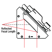
Figure 639B Beam Path Inside Right-Angle Kinematic OAP Mirror Mounts
(OAP Mirror Sold Separately)
Click to Enlarge
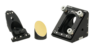
Figure 639A KCB1P Mounting Plate and Housing Body Shown with Off-Axis Parabolic Mirror (Sold Separately)
- Mount Ø1/2" (Ø12.7 mm) or Ø1" (Ø25.4 mm) Off-Axis Parabolic Mirrors at a Right Angle
- Eight 0.25" (6.35 mm) Deep Smooth Bore Holes for Ø6 mm ER Cage Rods
- Provides ±4° Kinematic Pitch and Yaw Adjustment
- Z-Axis Translation Using All Three Adjusters: ±0.12" (±3.0 mm)
- 30 mm Cage System and SM1 Lens Tube Compatible
- Two 1/4"-20 (M6 x 1.0) Taps for Mounting on Ø1/2" or Ø1" Posts
The KCB1P5(/M) and KCB1P(/M) right-angle mounts provide pitch and yaw adjustment for a Ø1/2" (Ø12.7 mm) (Item # KCB1P5(/M)) or a Ø1" (Ø25.4 mm) (Item # KCB1P(/M)) off-axis parabolic (OAP) mirror mounted on a plate that positions the surface of the mirror at a 45° angle. The ports are equipped with SM1-threaded (1.035"-40) bores and four 0.25" (6.4 mm) deep smooth bore holes spaced to mate with our 30 mm cage system. The cage rods are secured by eight setscrews using a 5/64" (2.0 mm) hex key or balldriver. This design allows multiple 30 mm cage components to be directly interfaced without the need for ERSCB ER Rod Adapters. The kinematic pitch and yaw adjustment plate is actuated with 100 TPI (Threads Per Inch) adjustment screws that provide an angular resolution of 7.6 mrad/rev. The knob on each adjuster is removable. While the optic face is nominally centered within the mount, the third adjuster can be used for fine tuning the position along the optical axis.
Three captive 4-40 cap screws in the optic mounting plate are used to secure the Ø1/2" (Ø12.7 mm) or Ø1" (Ø25.4 mm) off-axis parabolic mirror using a 5/64" (2.0 mm) hex key or balldriver. The rear-loading, removable mounting plate features our ball and V-groove design that allows it to be precisely kinematically positioned on the body of the mount. The plate and mount are held together using pairs of rare-earth magnets. Once mounted, the plate can be firmly secured in place using the captive locking screw with 5/64" (2.0 mm) hex on the back. The rear-loading design ensures that the optic remains accessible even after the mount is fitted with cage rods or lens tubes. The back of the mounting plate offers an engraved label for marking details about the installed mirror such as the focal length or part number. The mounting plate also features through bores for OAP mirrors with holes for the focused or collimated beams, though we do not currently stock these mirrors in a Ø1/2" or a Ø1" form factor. To request a quote for custom Ø1/2" or Ø1" OAP mirrors with holes, please contact Tech Support.

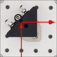
Click to Enlarge Figure G6.2 Alignment of Laser Beam Along Holes of Optical Table Using an RBP1 Post Base
Click to Enlarge
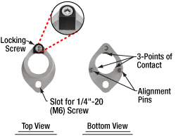
Figure G6.1 Top and Bottom View of the RBP1 Post Base
- Ideal for Aligning a Laser Beam Along the Threaded Holes of an Optical Table
- Compatible with Imperial and Metric Optical Tables and Ø1" or Ø25 mm Pillar Posts
- Alignment Pins and Attachment Screw Position the Front Surface of the Mirror in a KCB1(/M), KCB1C(/M), KCB1E(/M), KCB1EC(/M), or KCB1P5(/M) Mount Above a Hole in the Table
- Post Rotates Freely When Locking Screw is Loosened
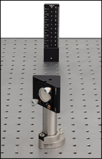
Click to Enlarge Figure G6.3 Using a BHM6 Ruler and RBP1 Base to Align a KCB1 Mount
The RBP1(/M) Pin-Aligned, Clamping Post Base is designed to simplify aligning a laser beam over the threaded holes in an imperial or metric optical table by holding the front surface of a mirror mounted in a KCB1(/M), KCB1C(/M), KCB1E(/M), KCB1EC(/M), or KCB1P5(/M) Right-Angle Kinematic Mirror Mount above a hole in the table. The clamping post base accepts Ø1" (Ø25 mm) Pillar Posts, to which the right-angle mirror mount can be connected as shown in Figure G6.3; note that the base does not accept pedestal posts. Alignment pins on the bottom of the RBP1(/M) post base fits into the holes on an optical table, which sets the mount in the correct position, while a 1/4"-20 (M6) cap screw and washer (not included) secure the clamp to the table. The body of the clamp is made of stainless steel, with an additional anodized aluminum piece that works with the locking screw to lock the post to the clamp.
Once the RBP1(/M) post base is attached to the table, the angle of the post can be set so that the mirror sends the beam along the general direction of the holes in the table by aligning the center of the back of the mount over the locking screw side of the clamp, as shown in Figure G6.2. To secure the post in place, tighten the locking screw with a 3/16” (5 mm) hex key or balldriver. The post clamping mechanism uses three points of contact for stable mounting (see Figure G6.1). The knobs on the mirror mount can then be used for further precise alignment of the beam. We recommend the BHM6 Magnetic Beam Height Ruler with Dowel Pins as an ideal tool for aligning a laser with a table's hole pattern using the RBP1(/M) post base, as it places a series of alignment holes at different heights above two threaded holes in the table (see Figure G6.3).
For our complete selection of Pin-Aligned, Clamping Post Bases, see the full web presentation.

Click to Enlarge
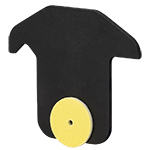
Figure 257A Front View of VRC1CPT Drop-In Alignment Plate
- Drop-In Beam Alignment Tools
- Small Through Hole Aligned at Center of 30 mm Cage Assembly
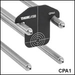
The CPA1 and CPA2 Alignment Plates are convenient tools for aligning cage-based optical systems. These drop-in plates feature a small through hole at the exact center of the 30 mm cage assembly that is used for aligning visible beams. For easy alignment, the through hole is surrounded by engraved rings, which indicate Ø4 mm, Ø7 mm, Ø10 mm, and Ø13 mm. The CPA1 provides a Ø0.9 mm through hole, while the CPA2 provides a Ø5 mm through hole.
The VRC1CPT, VRC2CPT, VRC8CPT, and VRC6SCPT Alignment Plates are specifically designed to align UV to MIR beams in a cage-based optical assembly. These plates have concentric alignment ring engravings identical to the CPA1 plate on the back. The fronts of the VRC1CPT, VRC2CPT, and VRC8CPT plates each include a Ø1/2" (Ø12.7 mm), non-rotating fluorescing alignment disk made of the same material used in our VRC1 and VRC2 viewing cards and VRC8B1 adhesive-backed material sheets, respectively. Alternatively, the front of the VRC6SCPT plate includes a Ø0.39" (Ø10.0 mm), non-rotating MIR alignment disk made of the same thermochromic liquid crystal material used in our VRC6S Viewing Card. The disk on the VRC1CPT, VRC2CPT, or VRC8CPT plate has a Ø1.5 mm hole centered on the plate's Ø0.9 mm hole, and the disk on the VRC6SCPT plate has a Ø2.0 mm hole centered on the plate's Ø0.9 mm hole.
 Products Home


 Zoom
Zoom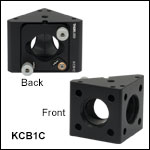

 Right-Angle Mirror Mounts