 Products Home
K-Cube® Laser Diode Driver
- Constant Current or Constant Power Operation
- Control Via Local Panel or USB PC Connection
- Full Software Control Suite Included
- Compact Footprint
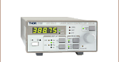
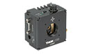
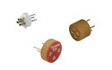
KLD101
Laser Diode Driver
(Power Supply Sold Separately)
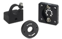
Included Mounting Plate
Kinesis Software Included


Please Wait
| Compact Light Source & Driver Modules |
|---|
| K-Cube® Modules |
| Laser Diode Driver |
| Laser Sources |
| T-Cube™ Module |
| LED Driver |
Features
- Current Output up to 230 mA
- LD Compliance Voltage up to 10 V at 50 mA
- Low Noise: <3.5 μA
- Constant Current and Constant Power Operating Modes
- Compact Housing: 121.0 mm x 60.0 mm x 47.0 mm (4.76" x 2.36" x 1.85")
- Safety Enable Key Switch and Laser Safety Interlock
- LCD Display Screen and Controls for Standalone Operation
- USB Connection for Remote PC-Controlled Operation
- Includes the Kinesis® Software Control Suite
- Single- and Multi-Channel Power Supply Options Available Separately
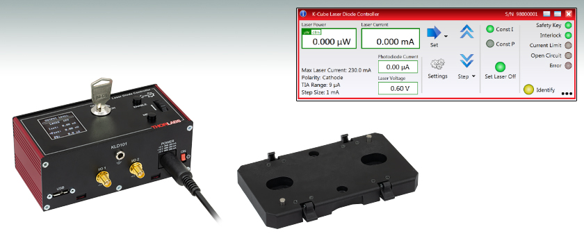
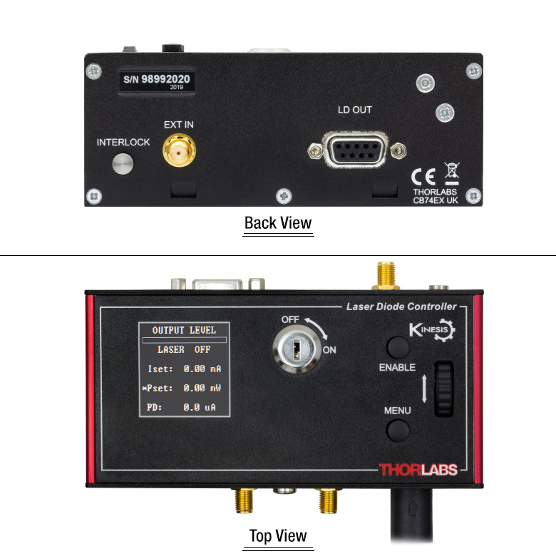
The KLD101 K-Cube® Laser Diode Controller is a compact, versatile module designed to drive a wide range of semiconductor laser diodes and LEDs. It supports operating currents up to 230 mA, a compliance voltage up to 10 V at 50 mA (>7 V at 230 mA), and both constant current and constant power operating modes. The KLD101 also enables the maximum drive current current to be set to prevent damage to the laser diode by accidental overdriving. As a member of the K-Cube family of products, this driver can be controlled locally using the screen and switches on the unit, or it can be controlled using a PC via the USB interface and included software.
The unit has a highly compact 121.0 mm x 60.0 mm footprint, allowing it to be positioned close to the rest of the system when manually adjusting the laser output using the top panel controls and convenient LCD display screen. A power switch on the front of the unit turns the K-Cube on and off, and the LCD screen displays information and settings upon startup, with or without a PC. When the unit is turned off, the K-Cube saves all user-adjusted settings for the next session. The power switch should always be in the "off" position when plugging in or unplugging the unit.
USB connectivity provides easy, plug-and-play, PC-controlled operation. The included Kinesis software package features .NET controls that can be used by third-party developers programming in C or C# and working in the latest LabVIEW™ or .NET compatible frameworks to create custom applications. For more details, please see the Kinesis Software and Kinesis Tutorials tabs. A USB 3.0 Type-A to type Micro-B cable is included with this K-Cube driver.
The K-Cube controller achieves its best performance when used with a suitable temperature controller and a laser diode mount with an integrated TEC element.
Optical Table Mounting Plate
Each unit comes with a mounting plate that attaches to the base of the module. The plate contains two magnets for temporary placement on an optical table and two counterbored slots for 1/4"-20 (M6) cap screws for a more permanent placement on the tabletop.
Power Supply Options
The preferred power supply (single channel, multi-channel, or hub-based) depends on the end user's application and whether you already own compatible power supplies. To that end and in keeping with Thorlabs' green initiative, we do not ship these units bundled with a power supply.
This K-Cube can be powered using our TPS002 power supply. If the TPS002 is used to power the KLD101, we do not recommend powering an additional K-Cube unit due the power supply's current limitations. Mutliple units can be connected to a single PC using the KCH301 or KCH601 USB Controller Hub (available below) for applications involving multiple K-Cubes. The KCH301 features three controller mounting bays while the KCH601 features six controller mounting bays. Note that these K-Cube drivers occupy two mounting bays on the USB controller hubs.
All power supply options compatible with the K-Cube laser diode driver can be found below.
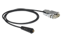
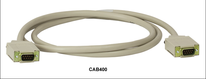
Connection Cables
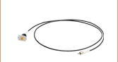
A CAB400 cable is required to connect the K-Cube laser diode controller to a Thorlabs Laser Diode Mount.
| Laser Diode Accessory Selection Guide | |||||
|---|---|---|---|---|---|
| Temperature Controlled Mounts | Passive Mounts | Passive Mounts with Collimation Package | Strain Relief Cables | Diode Sockets | Other Controllers |
 |
 |
 |
 |
 |
 |
| Item # | KLD101 |
|---|---|
| Laser Diode (LD) Output | 9-Pin D-Type |
| Max LD Current | 230 mA |
| Max LD Current Limit Range | 15 mA to 200 mA |
| LD Compliance Voltage | Up to 10 V at 50 mA (>7 V at 230 mA) |
| LD Current Setting Resolution | <8 µA |
| LD Power Setting Resolution | 1 µW |
| LD Current/Power Measurement Resolution | <0.4 µA (15 bit) |
| Output Current Accuracy (Constant Current Mode) | 0.2% (at 230 mA) |
| Temperature Drift | <40 ppm/°C (Typ.) |
| LD Current Noisea | <3.5 µA RMS (Typ.) at 46 mA over 20 Ω |
| LD Voltage Reading Accuracy | 3% of Full Scale (15 V) |
| Supported LD/PD Configurations | All |
| LD Protection | Relay - Open Circuit, Under/Over Voltage - 2 Interlocks |
| Operating Modes | Constant Current / Constant Power |
| Modulation Input | SMA: 0 to 10 V = 0 to Full Power, DC or Sine Wave Input Only |
| Modulation Bandwidthb | 20 kHz Full Depth (46 ksps) |
| Power Input | +15 V, -15 V, +5 V |
| USB Connector Type | USB 3.0 |
| USB Connection Speed | USB 1.1 Full Speed (12 Mbps) |
| Housing Dimensions (W x D x H) | 121.0 x 60.0 x 47.0 mm (4.76" x 2.36" x 1.85") |
| Weight | 400 g (0.88 lbs) |
Click to Enlarge
Mechanical Drawing of KLD101 Laser Diode Controller
Laser Diode Out
D-type Female
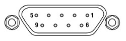
| Pin | Connection | Pin | Connection |
|---|---|---|---|
| 1 | Interlocka | 6 | Not Connected |
| 2 | Photodiode Cathode | 7 | Laser Diode Cathode (Polarity Anode Grounded) |
| 3 | Laser Diode Ground | 8 | Laser Diode Anode (Polarity Cathode Grounded) |
| 4 | Photodiode Anode | ||
| 5 | Ground for Pin 1a | 9 | Not Connected |
Computer Connection
The USB 3.0 port is compatible with a USB 2.0 Micro-B connector if the Micro-B connector is plugged into the shaded region in the photo above. A USB 3.0 Type-A to type Micro-B cable is included with the K-Cube®.
I/O 1 & 2
SMA Female
These connectors provide a 5 V logic level input and output that can be configured independently to support triggering into and out of external devices.
Ext In
SMA Female
Used to control the intensity of the laser output from an external source. This input can be driven from a 0 to 10 V voltage source. The input impedence is 16 kΩ.
Interlock
2.5 mm Pin

The interlock jack must be shorted with the included 2.5 mm pin or an external user gate before the laser may be enabled.
K-Cube® Mounting Options
Two options are available to securely mount our K-Cube® controllers onto an optical table. An optical table mounting plate, provided with every K-Cube, allows for a single controller to be attached to an optical table. Alternatively, three- and six-port USB controller hubs are offered (sold separately) that can mount and power our K-Cube controllers. These options are described in further detail below.
Optical Table Mounting Plate
Each K-Cube unit comes with a mounting plate that clips onto the base of the controller, as shown in the animation below. The plate contains two magnets for temporary placement on an optical table and two counterbores for 1/4"-20 (M6) cap screws for a more permanent placement on the tabletop. Please see the Specs tab for a mechanical drawing of the table mounting plate.
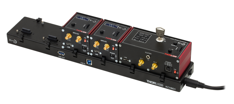
Kinesis USB Controller Hubs
Multiple units can be mounted and connected to a single PC by using the KCH301 or KCH601 USB Controller Hubs. They each consist of two parts: the hub, which can support up to three (KCH301) or six (KCH601) K-Cubes or T-Cubes, and a power supply that plugs into a standard wall outlet. K-Cubes simply clip into place using the provided on-unit clips, while current- and previous-generation T-Cubes require the KAP101 Adapter Plate, shown in the animation below. The hub vastly reduces the number of USB and power cables required when operating multiple controllers.
K-Cube Table Mounting Plate
Kinesis USB Controller Hubs
3- and 6-Port USB Controller Hubs allow multiple controllers to be connected to one PC for multi-axis applications. K-Cubes can be directly attached to the hubs while T-Cubes require a KAP101 Adapter Plate.
Software
Kinesis Version 1.14.52
The Kinesis Software Package, which includes a GUI for control of Thorlabs' Kinesis system controllers.
Also Available:
- Communications Protocol

Figure 58A Kinesis GUI Screen
Thorlabs offers the Kinesis® software package to drive our wide range of motion controllers. The software can be used to control devices in the Kinesis family, which covers a wide variety of motion controllers ranging from small, low-powered, single-channel drivers (such as the K-Cubes®) to high-power, multi-channel benchtop units and modular 19" rack nanopositioning systems (the MMR60x Rack System).
The Kinesis Software features .NET controls which can be used by 3rd party developers working in the latest C#, Visual Basic, LabVIEW™, or any .NET compatible languages to create custom applications. Low-level DLL libraries are included for applications not expected to use the .NET framework and APIs are included with each install. A Central Sequence Manager supports integration and synchronization of all Thorlabs motion control hardware.
By providing this common software platform, Thorlabs has ensured that users can mix and match any of our motion control devices in a single application, while only having to learn a single set of software tools. In this way, it is perfectly feasible to combine any of the controllers from single-axis to multi-axis systems and control all from a single, PC-based unified software interface.
The software package allows two methods of usage: graphical user interface (GUI) utilities for direct interaction with and control of the controllers 'out of the box', and a set of programming interfaces that allow custom-integrated positioning and alignment solutions to be easily programmed in the development language of choice.
Thorlabs' Kinesis® software features new .NET controls which can be used by third-party developers working in the latest C#, Visual Basic, LabVIEW™, or any .NET compatible languages to create custom applications.
C#
This programming language is designed to allow multiple programming paradigms, or languages, to be used, thus allowing for complex problems to be solved in an easy or efficient manner. It encompasses typing, imperative, declarative, functional, generic, object-oriented, and component-oriented programming. By providing functionality with this common software platform, Thorlabs has ensured that users can easily mix and match any of the Kinesis controllers in a single application, while only having to learn a single set of software tools. In this way, it is perfectly feasible to combine any of the controllers from the low-powered, single-axis to the high-powered, multi-axis systems and control all from a single, PC-based unified software interface.
The Kinesis System Software allows two methods of usage: graphical user interface (GUI) utilities for direct interaction and control of the controllers 'out of the box', and a set of programming interfaces that allow custom-integrated positioning and alignment solutions to be easily programmed in the development language of choice.
For a collection of example projects that can be compiled and run to demonstrate the different ways in which developers can build on the Kinesis motion control libraries, click on the links below. Please note that a separate integrated development environment (IDE) (e.g., Microsoft Visual Studio) will be required to execute the Quick Start examples. The C# example projects can be executed using the included .NET controls in the Kinesis software package (see the Kinesis Software tab for details).
 |
Click Here for the Kinesis with C# Quick Start Guide Click Here for C# Example Projects Click Here for Quick Start Device Control Examples |
|
LabVIEW
LabVIEW can be used to communicate with any Kinesis-based controller via .NET controls. In LabVIEW, you build a user interface, known as a front panel, with a set of tools and objects and then add code using graphical representations of functions to control the front panel objects. The LabVIEW tutorial, provided below, provides some information on using the .NET controls to create control GUIs for Kinesis-driven devices within LabVIEW. It includes an overview with basic information about using controllers in LabVIEW and explains the setup procedure that needs to be completed before using a LabVIEW GUI to operate a device.
 |
Click Here to View the LabVIEW Guide Click Here to View the Kinesis with LabVIEW Overview Page |
|
| Posted Comments: | |
user
(posted 2024-06-03 15:48:13.787) Hi. I would like to control the KLD101 with python. Is there any example file i can use? I have found for several K devices in the Thorlab's repository but not for this diode controller. cstroud
(posted 2024-06-07 04:15:31.0) Thanks for reaching out. Unfortunately we do not have an example program written with the .Net DLL's in Python, however we do have an example in C#. I will contact you directly to discuss this further. Takahiro Serikawa
(posted 2023-07-11 11:00:31.717) I bought KLD101 and tried external modulation. I wanted to apply constant current (for example 100mA) and change the LD current slightly (for example 10mA) by analog signal. The kinesis manual (ETN045988-D02, page 32) says:
>For example, if the maximum laser current is set to 75mA, then the 0 to 10V will result in an output current of 0 to 75mA (i.e.
the transconductance of the system is not constant, but depends on the initial set up). Note that this is in addition to the current
already set by the software or the OUTPUT control knob.
So I assumed that I can set the DC current on the kinesis software and add modulation current according to the SMA voltage. However the driving current was determined only by the external voltage when I enabled the external modulation. This behavior doesn't fit my application. Now I am add DC current bias to the SMA voltage and KLD101 is working fine, but I suggest correcting the expression in the manual not to confuse customers anymore. do'neill
(posted 2023-07-12 06:54:59.0) Response from Daniel at Thorlabs. Thank you for your feedback and your comments. We will review your suggestions and see what amendments are needed in the the manual. Again thank you for your suggestions. user
(posted 2023-02-01 15:24:04.443) Hello, I want to control KLD101 not with the Kinesis software but by pythonnet. Is there a document that has organized the usage of dll files? I want to look inside the files to know which functions I can call, but it seems for me the summary there are hard to understand. do'neill
(posted 2023-02-02 07:25:01.0) Response from Daniel at Thorlabs: Thank you for your enquiry. In the install folder, there an API help file for both sets of DLLs, both the C and the .NET DLLs. I will reach out to you to discuss your application directly. Holger Sahlmann
(posted 2021-10-28 04:33:35.233) Hello, is there any pin assigment for the power connector available? Thanks in advance, Holger DJayasuriya
(posted 2021-10-29 09:06:22.0) Thank you for your inquiery. We will get in touch with you directly. user
(posted 2020-02-20 07:47:20.36) I am currently looking at a both the KLD101 and LDC220C drivers and had a question regarding the modulation inputs. I understand the modes of operation but could not find any specification regarding the output speed when changing between levels of intensity. Is it solely a limitation of my external source or do these controllers ramp the current between intensity levels?
Ideally for my experiments I would like to pulse a laser diode very quickly (ie. 0 to max modulation).
Many Thanks in advance! DJayasuriya
(posted 2020-02-26 03:29:37.0) Response from Dinuka at Thorlabs: Unfortunately we do not have external analogue modulation on the KLD101 and LDC220C. However using a KLD101 it is possible to modulate the laser diode output by connecting a modulating signal to the rear panel MOD IN connector. The modulation bandwidth is 20 kHz full depth.You can find more detailed information in the corresponding manual(chapter 5):https://www.thorlabs.com/drawings/cdb7625d27edd0dc-05CB9220-D0F1-54B2-263CE7E602045518/KLD101-Manual.pdf DJayasuriya
(posted 2020-02-26 03:29:37.0) Response from Dinuka at Thorlabs: Unfortunately we do not have external analogue modulation on the KLD101 and LDC220C. However using a KLD101 it is possible to modulate the laser diode output by connecting a modulating signal to the rear panel MOD IN connector. The modulation bandwidth is 20 kHz full depth.You can find more detailed information in the corresponding manual(chapter 5):https://www.thorlabs.com/drawings/cdb7625d27edd0dc-05CB9220-D0F1-54B2-263CE7E602045518/KLD101-Manual.pdf user
(posted 2019-09-03 17:56:33.74) I am using SLED diode from EXALOS company. Style H type. Pin 1 is the anode, pin 2 is the cathode. So I looked at KLD101 pin map and connected pin 1 and pin 5. Connect pin 1 of diode to pin 8, pin 2 to pin 7, and press ENABLE button. However, an Open Circuit error message occurs. How do I solve it? AManickavasagam
(posted 2019-09-04 11:23:51.0) Response from Arunthathi at Thorlabs: Thanks for your query. Open circuit means that the KLD does not see the SLED diode or the voltage across the SLED diode is high (like 11-12V, considered abnormal or an open loop) Pin1 and Pin5 are for the interlock and would throw a different error message. I have contacted you directly for further details which would help to investigate further and to hopefully resolve the issue. young ho yun
(posted 2019-08-23 10:51:07.373) When I press the enable button, the interrok open! I get a message How do I fix it? rmiron
(posted 2019-08-27 10:16:54.0) Response from Radu at Thorlabs: Hello Young Ho Yun. Before the unit can be enabled, the key switch must be turned on and the provided INTERLOCK pin fitted (the interlock LED should light green when it is fitted). Furthermore, a short circuit must be applied across the interlock terminals of the LD OUT connector (pins 1 and 5 - see Fig. 3.8). If you went through all of these steps and are still unable to enable the unit, please contact your local technical support office. e.v.loenhout
(posted 2014-03-14 11:57:48.027) What is wrong if the Pdr L (photodiode Range) is set to Pdr L and stays to this. Despite I change the switches? msoulby
(posted 2014-03-18 10:57:59.0) Response from Mike at Thorlabs: You must ensure that when you set the photodiode range that the laser current is turned up to the current limit. This is to ensure that the photodiode produces a photocurrent; this can vary between devices so the switches should be adjusted from large to small until the correct range is found. If the photodiode is faulty or not present in your laser diode then the value will always remain at Pdr L (low) as there will be not photocurrent to set the device to. user
(posted 2013-04-30 11:10:42.72) After changing the laser (and laser polarity in the config) I press ‘Laser on’ and this thing immediately sends the MAXIMUM current through the laser (ILim=202 mA) and burns it. Could it be even more silly??? Why can’t it start from safe 0mA, so that I can increase it then manually? So frustrating!!
Secondly, I have to set ILim to 202 mA because I need analogue modulation of the laser current. If I set ILim to actual maximum laser current I have to apply -10V to drive laser current to 0mA. Now, why 10V and not 100V or 1kV??? Typical signal generators give a swing of +/-5 V, hence I have to set excessive ILim.
In overall the product is poorly designed, which is very disappointing. jlow
(posted 2013-05-03 11:33:00.0) Response from Jeremy at Thorlabs: Thank you for your feedback. If you press the “Laser On“ button, then the controller will go to the last set current value. In constant current mode, when the laser is not enabled, you should be able to set the output current or turn the pot until you reached the desired value. When you re-enable the TLD001 it will go to the new set current. With regard to the modulation, the contribution of modulation current is added to the current set by the software or the output knob. FOr more information on this, please refer to Section 5.5 of the manual (http://www.thorlabs.com/Thorcat/17800/TLD001-Manual.pdf). user
(posted 2011-12-09 13:51:42.0) A response from Tyler at Thorlabs: We will contact you to help with the setup of your laser source. The setting information is dependent on the laser diode, which means that you need to fill it out and save it before driving your laser diode. You will not need a power meter to get the system working. hebinfriendly
(posted 2011-12-08 23:05:32.0) Our laboratory bought your company’s TCLDM9, TTC001, TLD001 and two laser diodes. Here are several questions. First, is the power meter a must? Second, why there is a note ‘laser driver settings not yet implemented’ when clicking the ‘settings’ button in the APT software? Third, when does the laser diode work while I operate the TLD001 according to page 27 of the manual? Thanks for your help. tor
(posted 2010-12-10 11:52:33.0) Response from Tor at Thorlabs to Mark: We will be contacting you directly to answer your questions. tor
(posted 2010-12-09 13:13:32.0) Response from Tor at Thorlabs to MHUEBNER: Thank you for your interest in the TLD001. For details regarding the photodiode current settings, please refer to page 23 of the manual: http://www.thorlabs.de/Thorcat/17800/17874-D01.pdf . The LD power setting resolution is 1µW. The potentiometer is an infinite-turn potentiometer. The rate of change of the power output depends on how quickly you turn the pot; therefore, the number of turns would not uniquely determine a specific change in output power. The photodiode current can be monitored in the GUI software while the unit is in constant power mode. Our engineers advise that there is no spec for photodiode current accuracy, as this value may depend on the photodiode used. Please do not hesitate to contact us at techsupport@thorlabs.com if you have additional inquiries. MHUEBNER
(posted 2010-12-07 18:07:11.0) I would like to use the TLD001 to control the output power of a large number of different individual laser diodes, one at a time. I expect the photodiode current to be between 50 and 500 uA. What setting should I choose? How closely will the power be controlled (1%, 0.01mW)? How many pot turns from 0mW to 5mW? How many pot turns from 4.5mW to 5mW? Can I read the photodiode current while the unit is in constant power mode? What is the accuracy of the photodiode current reading? Thank you. |
Laser Diode Controller Selection Guide
Tables 137A and 137B are designed to give a quick overview of the key specifications for our laser diode controllers and dual diode/temperature controllers. For more details and specifications, or to order a specific item, click on the appropriate item number below.
| Table 137A Current Controllers | ||||||
|---|---|---|---|---|---|---|
| Item # | Drive Current | Compliance Voltage | Constant Current | Constant Power | Modulation | Package |
| LDC200CV | 20 mA | 6 V | External | Benchtop | ||
| VLDC002 | 25 mA | 5 V | - | Int/Ext | OEM | |
| LDC201CU | 100 mA | 5 V | External | Benchtop | ||
| LD2000R | 100 mA | 3.5 V | - | External | OEM | |
| EK2000 | 100 mA | 3.5 V | - | External | OEM | |
| LDC202C | 200 mA | 10 V | External | Benchtop | ||
| KLD101 | 230 mA | ≤10 V | External | K-Cube® | ||
| IP250-BV | 250 mA | 8 Va | External | OEM | ||
| LD1100 | 250 mA | 6.5 Va | - | -- | OEM | |
| LD1101 | 250 mA | 6.5 Va | - | -- | OEM | |
| EK1101 | 250 mA | 6.5 Va | - | -- | OEM | |
| EK1102 | 250 mA | 6.5 Va | - | -- | OEM | |
| LD1255R | 250 mA | 3.3 V | - | External | OEM | |
| LDC205C | 500 mA | 10 V | External | Benchtop | ||
| IP500 | 500 mA | 3 V | External | OEM | ||
| LDC210C | 1 A | 10 V | External | Benchtop | ||
| LDC220C | 2 A | 4 V | External | Benchtop | ||
| LD3000R | 2.5 A | -- | - | External | OEM | |
| LDC240C | 4 A | 5 V | External | Benchtop | ||
| LDC4005 | 5 A | 12 V | Int/Ext | Benchtop | ||
| LDC4020 | 20 A | 11 V | Int/Ext | Benchtop | ||
| Table 137B Dual Temperature and Current Controllers | |||||||
|---|---|---|---|---|---|---|---|
| Item # | Drive Current | Compliance Voltage | TEC Power (Max) | Constant Current | Constant Power | Modulation | Package |
| VITC002 | 25 mA | 5 V | >2 W | - | Int/Ext | OEM | |
| ITC102 | 200 mA | >4 V | 12 W | Ext | OEM | ||
| ITC110 | 1 A | >4 V | 12 W | Ext | OEM | ||
| ITC4001 | 1 A | 11 V | >96 W | Int/Ext | Benchtop | ||
| CLD1010LPa | 1.0 A | >8 V | >14.1 W | Ext | Benchtop | ||
| CLD1011LPb | 1.0 A | >8 V | >14.1 W | Ext | Benchtop | ||
| CLD1015c | 1.5 A | >4 V | >14.1 W | Ext | Benchtop | ||
| ITC4002QCLd | 2 A | 17 V | >225 W | Int/Ext | Benchtop | ||
| ITC133 | 3 A | >4 V | 18 W | Ext | OEM | ||
| ITC4005 | 5 A | 12 V | >225 W | Int/Ext | Benchtop | ||
| ITC4005QCLd | 5 A | 20 V | >225 W | Int/Ext | Benchtop | ||
| ITC4020 | 20 A | 11 V | >225 W | Int/Ext | Benchtop | ||
We also offer a variety of OEM and rack-mounted laser diode current & temperature controllers (OEM Modules, PRO8 Current Control Rack Modules, and PRO8 Current and Temperature Control Rack Modules).

 Zoom
Zoom- Top Panel Display Screen and Controls for Standalone Operation
- USB Connectivity for PC Operation with Kinesis® Software
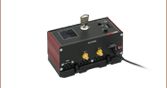
- Two External Trigger Ports (SMA Connectors)
- Compact Footprint: 121.0 mm x 60.0 mm x 47.0 mm (4.76" x 2.36" x 1.85")
- Power Supply and CAB400 Connection Cable Sold Separately (See Options Below)
The K-Cube® Laser Diode Driver provides local and computerized control of a laser diode or LED. It features top-panel controls that support both constant current and constant power operation modes. The digital display on the top panel includes a backlight that can be dimmed or turned off using the top panel menu options. The front of the unit contains two bidirectional trigger ports that can be used to read a 5 V external logic signal or output a 5 V logic signal to control external equipment. The CAB400 cable, sold separately below, is needed to connect KLD101 to our laser diode mounts.
The unit is fully compatible with our Kinesis software package. Please see the Kinesis Software tab for more information.
This K-Cube controller achieves its best performance when used with a suitable temperature controller and a laser diode mount with an integrated TEC element.
Please note that this controller does not ship with a power supply. Compatible power supplies are listed below. See the table to the right for assistance in choosing a power supply.

 Zoom
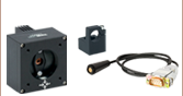
Zoom- Individual ±15 V/5 V Power Supply
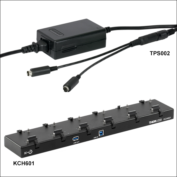
- TPS002: For up to Two K-Cubes® or T-Cubes™ with Mini-DIN Input*
- USB Controller Hubs Provide Power and Communications
- KCH301: For up to Three K-Cubes or T-Cubes
- KCH601: For up to Six K-Cubes or T-Cubes
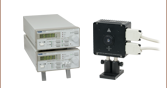
The TPS002 supplies power for up to two K-Cubes* or T-Cubes. The cubes still require individual computer connection via USB cable.
The KCH301 and KCH601 USB Controller Hubs each consist of two parts: the hub, which can support up to three (KCH301) or six (KCH601) K-Cubes or T-Cubes, and a power supply that plugs into a standard wall outlet. The hub draws a maximum current of 10 A; please verify that the cubes being used do not require a total current of more than 10 A. In addition, the hub provides USB connectivity to any docked K-Cube or T-Cube through a single USB connection.
For more information on the USB Controller Hubs, see the full web presentation.
*The TPS002 can only support one KNA-VIS or KNA-IR controller or one KLD101 driver and should not be used to power any additional units as that may exceed current limitations.

 Zoom
Zoom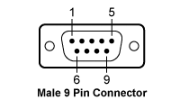
The CAB400 is needed to connect laser diode drivers to our laser diode mounts.
| CAB400 (9 Pin Male) Cable | |
|---|---|
| Pin # | Description |
| 1 | Interlock and Status LASER ON/OFF |
| 2 | Photodiodea |
| 3 | Laser Diode Ground |
| 4 | Photodiodeb |
| 5 | Ground for Pin 1 |
| 6 | Voltage Measurement Laser Diode Cathodec |
| 7 | Laser Diode Cathode (with Polarity Anode Grounded - AG) |
| 8 | Laser Diode Anode (with Polarity Cathode Grounded - CG) |
| 9 | Voltage Measurement Laser Diode Anodec |