 Products Home / Drivers & Mounts / OEM Laser Diode & TEC Systems / OEM Laser Diode Driver with Analog Modulation
OEM Laser Diode Driver with Analog Modulation
- 100 mA APC Diode Laser Driver, DC to 10 kHz Modulation
- Evaluation Kit, Pre-Wired for Laser Pin Style A
- 9 VDC Power Supply
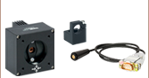
EK2000
LDS9 Power Supply
Sold Separately
LDS9
Power Supply
LD2000R
2" x 1.3" x 1/2"
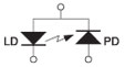
A Pin Configuration


Please Wait

LD2000R and EK2000 Evaluation Kit Features
- Constant Power Mode from 20 μA to 125 μA
- Laser Drive Currents from 0 to 100 mA
- EK2000 Suitable for Driving LEDs
- Ultra-Stable Laser Control
- On Board Trimpots are Provided for Controlling the Laser Power and Current Limit
- Slow Start for Diode Protection
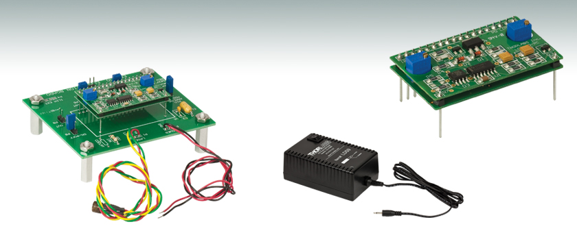
The LD2000R is a stable laser diode current source that can be operated with laser diodes having a common laser diode anode and monitor photodiode cathode. The driver operates in an automatic power control (APC) mode using the built-in monitor photodiode integrated in the laser diode for feedback. On board trimpots are provided for controlling the laser power and current limit. Both functions can also be controlled via an external voltage source. The driver supports a wide range of laser diodes with drive currents up to 100 mA and photodiode currents from 20 μA to 2 mA. It also has an external input for support of applications having a style A PIN configuration (common laser diode anode and photodiode cathode) requiring modulation of the laser output.
The EK2000 Laser Diode Driver Evaluation Kit allows users to quickly set up the LD2000R with a laser diode and a DC power supply without having to develop extensive hand-wiring or a custom PCB. All of the LD2000R features are supported with convenient, easy to use connector interfaces.
Compatible Pin Styles (when wired in a Style A configuration):
| PIN Style A | PIN Style D | PIN Style F* |
|---|---|---|
 |
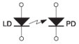 |
 *Supported by LD2000R Only |
| Item # | LD2000R | EK2000 |
|---|---|---|
| Current Output | ||
| Limit Current Control | Trimpot or External Analog Voltage | |
| Limit Current Range | 0 to 100 mA | |
| Limit Accuracy | ±1% | |
| Compliance Voltage | (V+/2) - ILIMIT * 5 | |
| Power Output | ||
| Photodiode Current Control | Trimpot or External Analog Voltage | |
| Photodiode Current Range | 20 to 125 μA | |
| Long Term Drift (24 hours) | <0.1% | |
| Temperature Coefficient | <100 ppm/ °C | |
| Analog Bandwidth | ||
| 3dB Bandwidth (Nominal) | 10 kHz (Actual Bandwidth is Laser Dependent) | |
| Power Supply | ||
| Supply Voltage (V+) | 8 to 12 VDC | |
| Supply Current | 30 mA Plus Laser Current | |
| General | ||
| Operating Temperature | 0 to 40 °C | -20 to 60 °C |
| Storage Temperature | 0 to 70 °C | -65 to 150 °C |
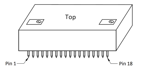
LD2000 Pin Configurations
| Pin | Signal | Description |
|---|---|---|
| 1 | CX1 | These pins are provided for connecting an external capacitor to the control loop integrator to extend the integrator time constant. This may necessary to get maximum bandwidth when using TTL modulation. Connect the positive terminal of the cap to CX2. |
| 2 | CX2 | |
| 3 | Analog Modulation | This pin is used with an external voltage signal source to provide analog modulation. The transfer function (referenced to the photodiode current) is -50 μA/V (see note 1) with 0 V being the laser completely on. The laser output decreases as this voltage increases with the laser being completely off at 2.5 V. Connect this pin to ground when not using the analog modulation. |
| 4 | Slow Start | This output pin is high during the start up period and goes low when the laser is enabled. It can be used as a LASER EMISSION indicator. An external capacitor can be connected from this pin to ground to extend the slow start delay time. Note: this output will not drive an LED directly and must be buffered (contact the factory for more details). |
| 5 | PD Current Trimpot | This pin is connected to the wiper of the on-board PD Current Trimpot. Connect this pin to the PD Current Setpoint to control the photodiode current with the on-board trimpot. |
| 6 | PD Current Setpoint | This pin controls the PD Current according to a transfer function of 50 μA/V with 0V being the laser is completely off (0 photodiode current). The laser output increases as this voltage increases. |
| 7 | REF Out | This is a buffered 2.5 V voltage reference. |
| 8 | PD AMP Out | This is an analog voltage proportional to the photodiode current and referenced to one half the supply voltage. |
| 9 | +V | Positive supply voltage (+8 to +12 VDC). |
| 10 | Ground | Power supply common. |
| 11 | LD A/PD K | Common laser diode anode, photodiode cathode. |
| 12 | PD A | Photodiode anode. |
| 13 | LD K | Laser diode cathode. |
| 14 | Limit Setpoint | This voltage determines the maximum laser drive current according to the transfer function 46 mA/V. |
| 15 | Limit Trimpot | This is connected to the wiper of the Limit Current trimpot. Connect this to the Limit Setpoint pin to use the on-board trimpot to set the current limit. |
| 16 | Not Used | This must be tied to ground to operate the laser. |
| 17 | On/Off | This pin is used to externally turn the laser on and off through the slow start circuit and to set the low voltage dropout point. It has an internal 20 kΩ resistor to ground. Connect a 15 kΩ resistor to the power supply voltage to set the dropout voltage to 4.5 V. |
| 18 | Limit Out | This is an output voltage proportional to the limit current with a transfer function of 40 mA/V. Use this pin to assist in setting the laser current limit. |
Click to Enlarge
EK2000 Packaging

Smart Pack
- Reduce Weight of Packaging
- Increase Usage of Recyclable Materials
- Improve Packing Integrity
- Decrease Shipping Costs
Thorlabs' Smart Pack Initiative is aimed at minimizing waste while providing adequate protection for our products. By eliminating any unnecessary packaging, implementing design changes, and utilizing eco-friendly materials, this initiative seeks to reduce the environmental impact of our product packaging.
The updated EK2000 packaging primarily consists of recycled paper and cardboard and weighs 21.84% less than the original packaging. This weight change results in a 1.35 kg reduction in travel-based CO2 emissions per year, based on typical product sales.
As we move through our product line, we will indicate re-engineered, eco-friendly packaging with our Smart Pack logo, which can be seen above.
| Posted Comments: | |
luis.marin
(posted 2017-07-03 13:36:22.14) I need to connect style D to this driver, suggestions please... tfrisch
(posted 2017-08-03 04:47:59.0) Hello, thank you for contacting Thorlabs. This evaluation kit is compatible with style D. The floating PD cathode would be tied to ground. I will reach out to you directly to discuss this. pt_tanyingjie
(posted 2013-07-21 21:26:31.25) May i know which type of OEM driver i could use to drive LP520-SF15, which is PIN code 9E? cdaly
(posted 2013-08-02 10:20:00.0) Response from Chris at Thorlabs: Thank you for using our feedback tool. Any source which provide 180mA at the operating voltage of 7.5V should be sufficient. Pin code is only really going to affect those mounts which already have pre-wired sockets for the diode. For the LP520-SF15, I would suggest using the IP250-BV, which despite its description can be used for diodes other than blue ones. jlow
(posted 2012-09-13 12:03:00.0) Response from Jeremy at Thorlabs: It seems that the website wasn't updated to reflect the manual. We are updating the website now to fix this error. Thank you for bringing this to our attention. For your application of 25kHz with a Style A laser diode, maybe the IP500 could work for you? The bandwidth for that is DC to 50kHz. I will contact you directly to discuss about your application further. bernard.wenger
(posted 2012-09-11 05:57:42.0) In the specs on the web page the analog bandwidth is 30 kHZ, however in the datasheet this is only 10 kHz. I need a 25 kHz modulation, will it work? kalun
(posted 2011-01-12 14:19:54.0) I would like to built a fiber link using EK2000, Pigtailed Laser Diodes, Single Mode Fiber and speaker. I have questions on the modulation signal to the P10 of EK2000. Does it only accept 0-2.5V signal? If I have a mp3 player, how can I input this signal to the EK2000? Thorlabs
(posted 2010-09-08 18:50:58.0) Response from Javier at Thorlabs to bpetrig: the LD2000 is not designed to drive C type laser diodes. It will only work with the styles A, B, and D. I would recommend using the LD1101 for C type diodes:
http://www.thorlabs.de/NewGroupPage9.cfm?ObjectGroup_ID=1364&pn=LD1100&CFID=2724616&CFTOKEN=52976594
The main advantage of the LD2000 over the LD1101 is that it features an external control input for modulation up to ~30 kHz. bpetrig
(posted 2010-09-08 14:29:33.0) I am wondering if the LD2000 can be used to drive a "Style C" type laser, such as the laser
P/N DL7140-201S, in automatic power control mode?
What advantage(s) does the LD2000 laser driver offer compared to the LD1100? |
Laser Diode Controller Selection Guide
The tables below are designed to give a quick overview of the key specifications for our laser diode controllers and dual diode/temperature controllers. For more details and specifications, or to order a specific item, click on the appropriate item number below.
| Current Controllers | ||||||
|---|---|---|---|---|---|---|
| Item # | Drive Current | Compliance Voltage | Constant Current | Constant Power | Modulation | Package |
| LDC200CV | 20 mA | 6 V | External | Benchtop | ||
| VLDC002 | 25 mA | 5 V | - | Int/Ext | OEM | |
| LDC201CU | 100 mA | 5 V | External | Benchtop | ||
| LD2000R | 100 mA | 3.5 V | - | External | OEM | |
| EK2000 | 100 mA | 3.5 V | - | External | OEM | |
| LDC202C | 200 mA | 10 V | External | Benchtop | ||
| KLD101 | 230 mA | ≤10 V | External | K-Cube™ | ||
| IP250-BV | 250 mA | 8 Va | External | OEM | ||
| LD1100 | 250 mA | 6.5 Va | - | -- | OEM | |
| LD1101 | 250 mA | 6.5 Va | - | -- | OEM | |
| EK1101 | 250 mA | 6.5 Va | - | -- | OEM | |
| EK1102 | 250 mA | 6.5 Va | - | -- | OEM | |
| LD1255R | 250 mA | 3.3 V | - | External | OEM | |
| LDC205C | 500 mA | 10 V | External | Benchtop | ||
| IP500 | 500 mA | 3 V | External | OEM | ||
| LDC210C | 1 A | 10 V | External | Benchtop | ||
| LDC220C | 2 A | 4 V | External | Benchtop | ||
| LD3000R | 2.5 A | -- | - | External | OEM | |
| LDC240C | 4 A | 5 V | External | Benchtop | ||
| LDC4005 | 5 A | 12 V | Int/Ext | Benchtop | ||
| LDC4020 | 20 A | 11 V | Int/Ext | Benchtop | ||
| Dual Temperature and Current Controllers | |||||||
|---|---|---|---|---|---|---|---|
| Item # | Drive Current | Compliance Voltage | TEC Power (Max) | Constant Current | Constant Power | Modulation | Package |
| VITC002 | 25 mA | 5 V | >2 W | - | Int/Ext | OEM | |
| ITC102 | 200 mA | >4 V | 12 W | Ext | OEM | ||
| ITC110 | 1 A | >4 V | 12 W | Ext | OEM | ||
| ITC4001 | 1 A | 11 V | >96 W | Int/Ext | Benchtop | ||
| CLD1010LPa | 1.0 A | >8 V | >14.1 W | Ext | Benchtop | ||
| CLD1011LPb | 1.0 A | >8 V | >14.1 W | Ext | Benchtop | ||
| CLD1015c | 1.5 A | >4 V | >14.1 W | Ext | Benchtop | ||
| ITC4002QCLd | 2 A | 17 V | >225 W | Int/Ext | Benchtop | ||
| ITC133 | 3 A | >4 V | 18 W | Ext | OEM | ||
| ITC4005 | 5 A | 12 V | >225 W | Int/Ext | Benchtop | ||
| ITC4005QCLd | 5 A | 20 V | >225 W | Int/Ext | Benchtop | ||
| ITC4020 | 20 A | 11 V | >225 W | Int/Ext | Benchtop | ||
We also offer a variety of OEM and rack-mounted laser diode current & temperature controllers (OEM Modules, PRO8 Current Control Rack Modules, and PRO8 Current and Temperature Control Rack Modules).