 Products Home
DC Bias Module for Mounted Photodiodes
- Apply a DC Bias Voltage to Our Mounted Photodiodes
- Delrin®* Housing Isolates Connectors and Bias Source
- Maximum Bias Voltage of ±25 V
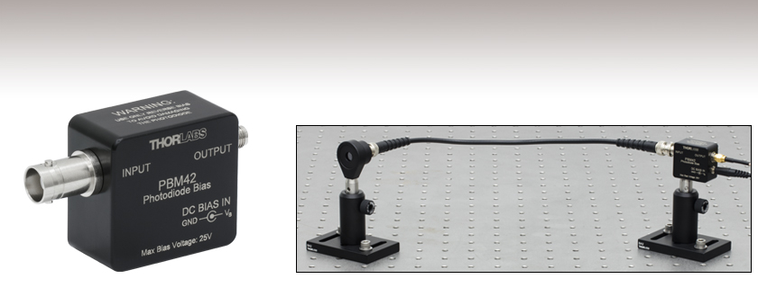
PBM42
Photodiode Bias Module with
BNC Input and SMA Output
Application Idea
SM1PD2A Mounted Photodiode Connected to the PBM42 by a BNC Cable


Please Wait
Click to Enlarge
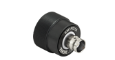
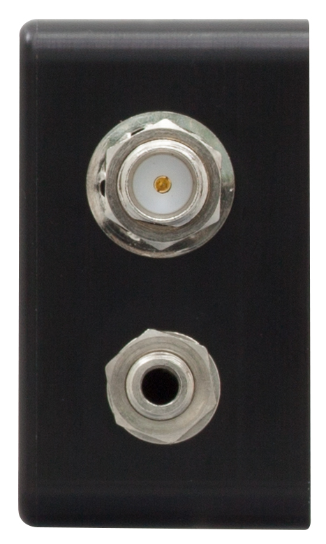
Figure 1.2 Female SMA Photodiode Output Connector (Top) and 2.5 mm Phono Jack DC Input (Bottom)
Click to Enlarge
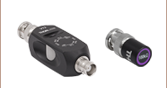
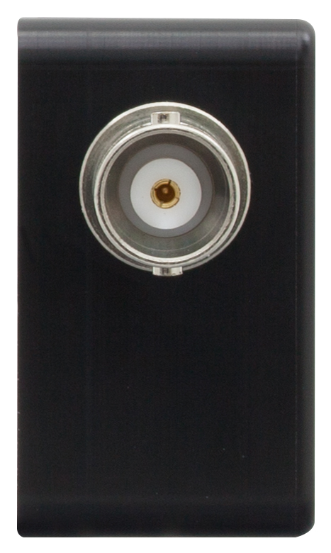
Figure 1.1 Female BNC Photodiode Input Connector
Features
- Module for Biasing Our Mounted Photodiodes
- Maximum Bandwidth: 350 MHz
- Post Mountable via Bottom-Located 8-32 and M4 Taps
- Compact Size: 2.48" x 1.40" x 0.80" (63.0 mm x 35.6 mm x 20.3 mm)
The PBM42 Bias Module allows a DC bias voltage from a user-supplied, external source to be applied to photodiodes. Designed for use with our mounted photodiodes, the module can accept an input bias voltage from -25 to +25 V from a user-supplied source and has a maximum bandwidth of 350 MHz (dependent on the photodiode). By adding a reverse bias to a photodiode, the width of the depletion junction in the photodiode is increased, thereby increasing the responsivity, decreasing the junction capacitance, and improving the linearity of the response. Operating under these conditions can produce a larger dark current, depending on the photodiode material.
The input side of the bias module has a BNC connector that can be connected to any of our mounted photodiodes equipped with the same connector by using a BNC cable or T3533 BNC adapter. Alternatively, the input side can be connected to any of our mounted photodiodes with SMA connectors by using an SMA-to-BNC cable or T4288 SMA-to-BNC adapter.
The bias module has an SMA connector on the output side and a 2.5 mm phono jack for the DC voltage input. A 72"-long cable with a 2.5 mm phono plug on one end and bare wires on the other is included with the module. Please note that the photodiode should be operated with a reverse bias. Forward biasing the photodiode can cause damage. For cathode-grounded photodiodes, the tip of the phono plug must be positive. For anode-grounded photodiodes, the tip of the phono plug must be negative. We recommend using a low-noise power supply with the module. For grounding and reverse bias voltage information on all our mounted photodiodes, please see the Photodiode tab.
For best frequency performance, the output of the bias module should be terminated with a 50 Ω cable and a 50 Ω impedance device or terminator, such as our T4119. For flexibility in output voltage, the VT2 variable terminator can also be used.
To ensure electrical isolation of the connectors and to protect the photodiode, the compact housing of the PBM42 is constructed from Delrin®*. Additionally, the housing offers one 8-32-tapped hole and one M4-tapped hole for mounting on our Ø1/2" posts, as shown in the photo at the top of the page.
*Delrin is a registered trademark of DuPont Polymers, Inc.
| Specifications | |||||||
|---|---|---|---|---|---|---|---|
| Item # | Bias Voltage | Cutoff Frequencya | Photodiode Input Connector | Output Connector | DC Input Connector | Housing Dimensions | Operating/Storage Temperature |
| PBM42 | -25 to +25 V | 350 MHz | Female BNC | Female SMA | 2.5 mm Phono (Cable Included) |
2.48" x 1.40" x 0.80" (63.0 mm x 35.6 mm x 20.3 mm) |
0 to 40 °C |
Thorlabs' Mounted Photodiodes Key Specifications
| Item # | Material | Grounding | Reverse Bias Voltage (Max) | Bandwidtha |
|---|---|---|---|---|
| SM1PD1A | Silicon | Cathode Grounded | 25 V | 8.8 MHz |
| SM1PD1B | Silicon | Anode Grounded | 25 V | 8.8 MHz |
| SM1PD2A | UV-Enhanced Silicon | Cathode Grounded | 5 V | 7.8 MHz |
| SM1PD5A | Germanium | Cathode Grounded | 1 V | 0.12 MHz |
| SM05PD1A | Silicon | Cathode Grounded | 25 V | 35 MHz |
| SM05PD2A | Silicon | Cathode Grounded | 25 V | 350 MHz |
| SM05PD3A | Silicon | Cathode Grounded | 30 V | 23 MHz |
| SM05PD4A | InGaAs | Cathode Grounded | 5 V | 50 MHz |
| SM05PD5A | InGaAs | Cathode Grounded | 3 V | 5.3 MHz |
| SM05PD6A | Germanium | Cathode Grounded | 3 V | 0.70 MHz |
| SM05PD1B | Silicon | Anode Grounded | 25 V | 35 MHz |
| SM05PD2B | Silicon | Anode Grounded | 25 V | 350 MHz |
Click to Enlarge
Figure 3.2 Example Circuit Diagram for Attaching the PBM42 Bias Module to a Cathode-Grounded Photodiode

Click to Enlarge
Figure 3.1 Example Circuit Diagram for Attaching the PBM42 Bias Module to an Anode-Grounded Photodiode
| Posted Comments: | |
Alexander Parfenov
(posted 2024-08-15 11:56:05.433) Do you have similar with BNC on both sides ? ksosnowski
(posted 2024-08-19 05:44:35.0) Hello Alexander, thank you for reaching out to us. For this purpose we offer adapters like T4001 to convert to BNC male or T4290 to convert to BNC female. We also offer SMA to BNC cables like CA2806 that can be used to connect to a BNC measurement device. We have not offered a BNC output version before as there are a few ways to adapt this one. Connor Gallimore
(posted 2024-05-01 10:56:45.98) I'm also having trouble with the size of the 2.5 mm phono jack. The response of the PD is weak when plugged into our Furman power conditioner. I initially thought it may be due to the fact that the power conditioner is maxed out (8 outlets), though plugging into a lone wall outlet still produces weak responses which are no different from when it is unplugged, suggesting it isnt receiving power. What kind of external power supply is recommended for attachment to the bare wires? Is it possible the loose fit indicates a manufacturing oddity on the PBM42 module itself? ksosnowski
(posted 2024-05-10 05:52:14.0) Hello Connor, thanks for reaching out to Thorlabs. A stable benchtop voltage supply with low ripple is recommended for providing bias so that no noise is added to the photodiode measurement. The applied bias voltage and polarity can be double checked by probing the photodiode connector, as the bias supply is passed to this connector through an RC lowpass noise filter by the PBM42's design. It is important to note the polarity of the bias applied vs the photodiode polarity to ensure that only a reverse bias is used, which in some cases requires a tip-grounded voltage to be applied on the phono cable. I have reached out directly to troubleshoot your issues further. user
(posted 2021-12-20 12:05:19.077) I use SM05PD1B1b and its power supply PBM42. In order to supply power to PBM42, the power supply voltage is set to be 20V, the silver wire is connected to the positive grounding, the white wire is connected to the negative, and M4 is grounded. However, there's no signal in the output. What should I do to make it work? cdolbashian
(posted 2022-01-25 04:41:19.0) Thank you for reaching out to us at Thorlabs! I have contacted you directly to troubleshoot your issues and illuminate you on the standard use process of these components. user
(posted 2019-04-02 14:12:36.737) I'm having problems plugging the 2.5 mm phono plugs included together to the actual PBM42. They simply are too small compared to the hole and cannot be fixed. Is my instruction a problem or are there anything extra that is needed for stable plugging? YLohia
(posted 2019-04-04 04:21:53.0) Hello, thank you for contacting Thorlabs. Please accept our apologies for the inconvenience caused by this product. I have been in touch with you to get a return initiated. henry.ke
(posted 2018-09-11 02:22:10.69) 我使用SM1PD5A detector +PBM42,逆向偏壓3V,但發現電流增加到3mA就飽和了,若沒有使用PBM42時,detector電流可以非常線性的到10mA沒有問題
請教一下使用逆向偏壓的目的不就是要增加線性度嗎? YLohia
(posted 2018-10-05 01:54:29.0) Hello, thank you for contacting Thorlabs. Inside the PBM42 is an RC circuit used for cleaning up the noise from the power supply but also to current limit and protect the PD in the case it is reverse connected. The resistor is limiting the current in your case that causes saturation. Please note that the bandwidth is also affected since the voltage drop across the resistor lowers the bias voltage, which results in a larger junction capacitance and lowers the bandwidth. juyoungk
(posted 2015-02-18 15:55:03.613) Hi,
I am confused of what the proper polarity is for the reverse bias of my photodiode. In manual page 6, it says,
"For Cathode grounded diodes center pin of phone plug is positive. For Anode grounded diodes center pin of phone plug is negative."
I purchased Cathode grounded diode (SM1PD1A). Should I apply positive voltage on the center pin of phone plug?
I would appreciate your help. Thank you. jlow
(posted 2015-02-24 04:45:07.0) Response from Jeremy at Thorlabs: The SM1PD1A is cathode grounded so you should apply a positive voltage to the tip of the phono plug. |