 Products Home / Telecommunications Instruments / High-Speed Detectors and Receivers / High-Speed Photoreceiver Modules, Fiber Coupled, OEM Package
High-Speed Photoreceiver Modules, Fiber Coupled, OEM Package
- Maximum Bandwidth from 10 GHz to 42 GHz
- Integrated Photodiode and Amplifier
- Single Mode and Multimode Versions Available
- Compact, Hermetic Package, Ideal for OEM Applications
RX10AF
SM, 10 GHz, 780 - 1650 nm,
Female 2.92 mm Connector
RX33BF
MM, 33 GHz, 750 - 1650 nm,
Differential SMPM (GPPO®* Compatible) Connectors
RX42AF
SM, 42 GHz, 800 - 1650 nm,
Differential SMPM
(GPPO®* Compatible) Connectors
*GPPO is a registered trademark of Corning.


Please Wait
Click to Enlarge
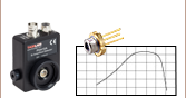
Figure 1.1 While each RX Series model is designed and intended for operation over the specified wavelength range shown by the solid colored regions, each will respond with reduced performance to optical inputs at shorter wavelengths, as shown by the partially transparent regions.

Adam Knapp
Ultrafast Optoelectronics
General Manager
Got Questions?
Our engineers and expertise are here for you!
If you are not sure whether our catalog items meet your needs, we invite you to contact us. Or ask about a loan, so you can try them out for yourself, in your own lab. We can also support custom or OEM requirements you may have.
Just press the button, and we'll get back to you within the next business day.

Features
- Fiber-Coupled Receivers with Bandwidths Up to 42 GHz
- Available from Stock with FC/PC Connectors; Contact Tech Support for FC/APC Versions
- AC-Coupled RF Outputs
- Hermetically Sealed Receiver Module with a GaAs or InGaAs Photodiode
- Single Mode and Multimode Versions:
- OM4 (Ø50 µm Core) Multimode Fiber
- SMF-28 Single Mode Fiber
- 3.3 V Power Requirement (User Supplied)
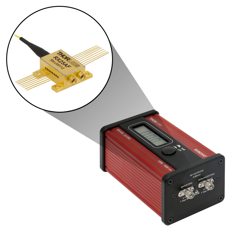
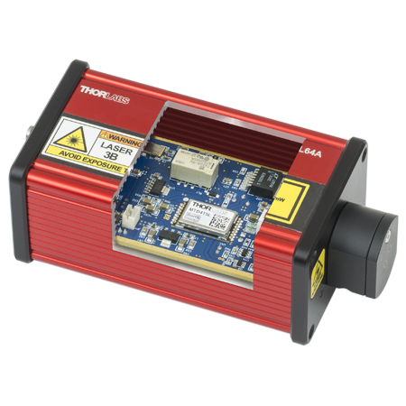
- Available Packaged in Ultrafast Receiver Instruments
- Discounts for High-Volume Purchases Available; Contact OEM Sales with Inquiries
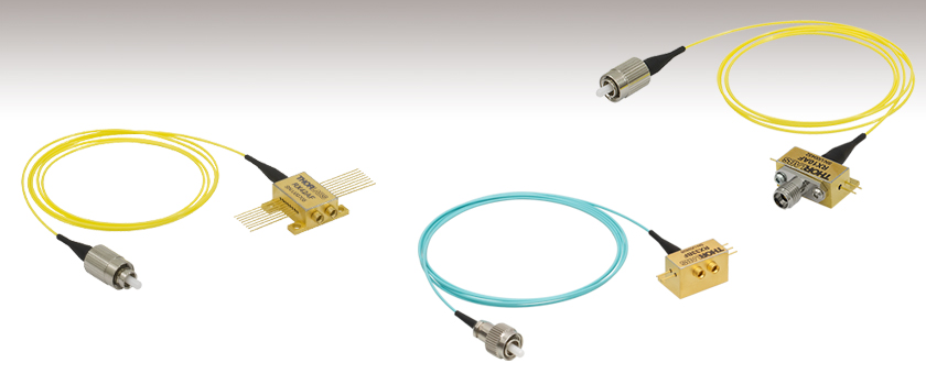
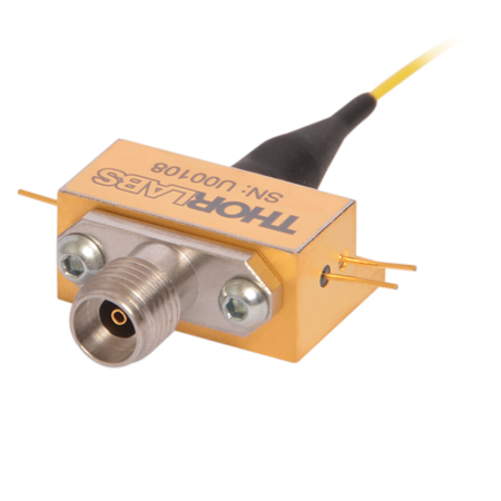
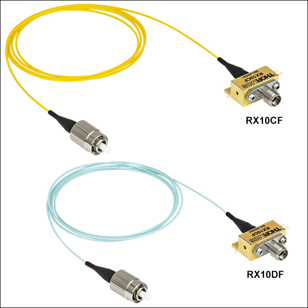
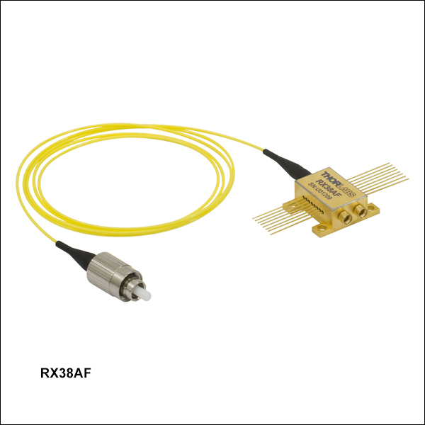
Thorlabs' RX Series of High-Speed Receivers combine a photodiode and transimpedance amplifier in a compact hermetic package with a pigtailed fiber input. Available with maximum bandwidths of 10 GHz, 25 GHz, 33 GHz, 38 GHz, 40 GHz, or 42 GHz, they are designed for use as components in systems where the user needs a reliable, high-bandwidth detection device.
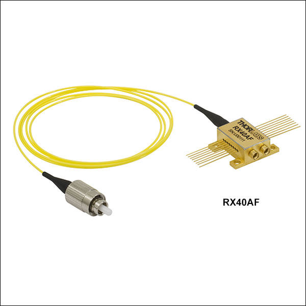
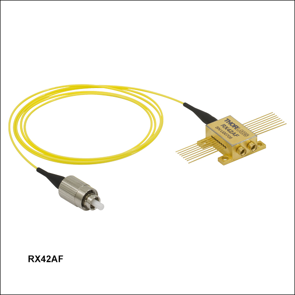
The RX33, RX38 and RX42 series receivers use the same amplifier but different photodiodes. The 33 GHz photoreceiver uses a larger photodiode that is slower and has a lower bandwidth, but makes it possible to couple light from a multimode input fiber. The 38 GHz photoreceiver uses a photodiode which has slightly higher responsivity, but less bandwidth. The RX42AF receiver uses a photodiode that has higher bandwidth, but less responsivity. The RX40AF photoreceiver provides a larger output swing than either the RX38AF or RX42AF receivers. However, the RX33BF, RX38AF and RX42AF receivers have a smoother frequency response roll-off, lower noise, and less change in frequency response as a function of gain. See the specifications for each device below, including fiber type, spectral response, and conversion gain.
Ideally, these items should be mounted to a printed circuit board (PCB) that supplies power and control signals that are free of noise and spikes. The fiber pigtail allows the input to be routed to another location off the PCB. All these receivers use FC/PC connectors as standard, but FC/APC connectors are available upon request; please contact Tech Support with inquiries. The coaxial output connectors (2.92 mm or dual SMPM (GPPO®* Compatible), depending on device) allow for cables to be connected to the module and then routed to the follow-on hardware. The outputs are designed for 50 Ω coaxial cable and should be terminated into 50 Ω equipment to prevent electrical reflections. These high-speed photoreceiver modules are ESD sensitive, so observe proper storage and handling procedures (see the Operation tab for details).
The performance of each RX series ultrafast photoreceiver is factory tested, and a summary of the individualized test results is shipped with each receiver. For receivers purchased after January 16th, 2020, a file with both this summary sheet and supporting test data can be downloaded by clicking on the red Docs icon ( ) next to the Item # and entering your device's serial number under "Download Serial Item Data." Data files for devices purchased before this date are available by contacting Tech Support. A sample of these results for the RX25BF ultrafast photoreceiver can be viewed here.
*GPPO is a registered trademark of Corning.
| Webpage Features | |
|---|---|
| Clicking this icon below opens a window that contains full specifications and performance graphs for each item. | |
|
Clicking this icon below allows you to download our standard support documentation for each item. |

ESD Sensitive Components: Please note that the components inside these modules are ESD sensitive. Take all appropriate precautions to discharge personnel and equipment before making any electrical connections to the unit. This especially applies to coaxial connecting cables that can accumulate capacitive charge.
Operation Guide for RX10 Series Photoreceivers
Please reference Figure 2.1 for connectors and pin assignments; Figure 2.2 depicts the internal elements of the photoreceiver. Unpack the unit carefully, making sure to take ESD precautions. For detailed operation procedures, refer to the spec sheet for each item #, accessible by clicking the Support Docs icon () below.
- Mount the unit using the Ø2.1 mm mounting holes.
- Attach the 2.92 mm output of the unit to the measurement instrument using suitable cables or adapters. The measurement instrument must have a 50 Ω input and adequate bandwidth to resolve the high-speed signal from the detector.
- It is critical that the power up and power down sequence is performed correctly:
- Power-Up Sequence: Photodiode First, Then Amplifier
- Power-Down Sequence: Amplifier First, Then Photodiode
- Couple the optical input signal to the photoreceiver via the FC/PC connector after the photodiode and amplifier are biased. Ensure the average input optical power does not exceed 6 dBm.
- The DC photocurrent can be monitored using a resistor in series with the bias pin and a voltmeter across the resistor. Make sure that the voltage drop across the resistor does not reduce the bias on the module below its operating voltage.
Click to Enlarge
Figure 2.2 RX10 Series Internal Block Diagram Showing the Photodiode, Amplifier Stage, and RF Output
Click to Enlarge
Figure 2.1 RX10 Series Device Schematic
Operation Guide for RX25 Series, RX33BF, RX38AF, RX40AF, and RX42AF Photoreceivers
Please reference Figures 2.3, 2.5, and 2.7 for connectors and pin assignments; Figures 2.4 and 2.6 depict the internal elements of the photoreceiver. Unpack the unit carefully, making sure to take ESD precautions. For detailed operation procedures, refer to the spec sheet for each item #, accessible by clicking the corresponding Support Docs icon () below. For pin assigments, click on the blue icons (![]() ) in the tables below and go to the Pin-Out Connections tabs.
) in the tables below and go to the Pin-Out Connections tabs.
- Mount the unit using the M2.5 x 0.45 (Ø2.1 mm for RX33BF) mounting holes. It is possible to use M2 screws for mounting if bypassing the M2.5 threads in the feet is desired. For RX33BF, M2 screws should be used.
- Attach the GPPO®* (SMPM for RX33BF) RF outputs of the unit to the measurement instrument using suitable cables or adapters. The measurement instrument must have a 50 Ω input and adequate bandwidth to resolve the high-speed signal from the detector. If only one output is used the other output must be terminated with a high quality 50 Ω termination.
- See datasheet for the pin out and detailed instructions to bias the device. It is critical that the power up and power down sequence is performed correctly:
- Power-Up Sequence: Photodiode First, Then Amplifier, Then Control Pins
- Power-Down Sequence: Control Pins First, Then Amplifier, Then Photodiode
- Couple the optical input signal to the photoreceiver via the FC/PC connector. Ensure the average input optical power does not exceed 10 dBm for the 25 GHz, 33 GHz, 40 GHz, and 42 GHz units or 7 dBm for the 38 GHz unit.
- The DC photocurrent can be monitored using a resistor in series with the bias pin and a voltmeter across the resistor. Make sure that the voltage drop across the resistor does not reduce the bias on the module below its operating voltage.
*GPPO is a registered trademark of Corning.
Click to Enlarge
Figure 2.4 RX25AF, RX25BF, RX25DF, and RX40AF Internal Block Diagram Showing the Photodiode,
Amplifier Stages, Control Pins, and Differential RF Outputs
Click to Enlarge
Figure 2.3 RX25DF, RX25AF, and RX40AF Device Schematic
Click to Enlarge
Figure 2.6 RX33BF, RX38AF and RX42AF Internal Block Diagram Showing the Photodiode,
Amplifier Stages, Control Pins, and Differential RF Outputs
Click to Enlarge
Figure 2.5 RX38AF and RX42AF Device Schematic

Click to Enlarge
Figure 2.7 RX33BF Device Schematic
Adam Knapp
Ultrafast Optoelectronics
General Manager
Custom and OEM Options
When your application requirements are not met by our range of catalog products or their variety of user-configurable features, please contact me to discuss how we may serve your custom or OEM needs.
Request a Demo Unit
Explore the benefits of using a Thorlabs high-speed instrument in your setup and under your test conditions with a demo unit. Contact me for details.
![]()
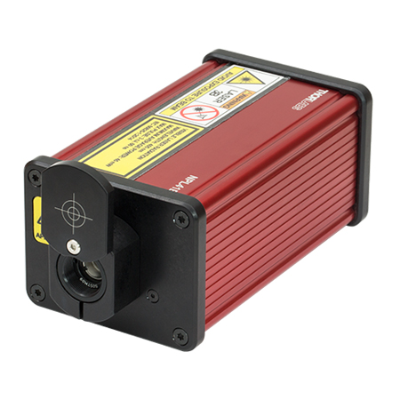
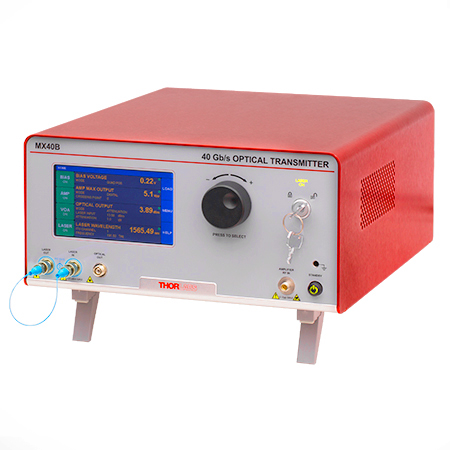
Click to Enlarge
Figure 162A The MX40B Digital Reference Transmitter
Design, Manufacturing, and Testing Capabilities
Thorlabs' Ultrafast Optoelectronics Team designs, develops, and manufactures high-speed components and instrumentation for a variety of photonics applications having frequency responses up to 110 GHz. Our extensive experience in high-speed photonics is supported by core expertise in RF/microwave design, optics, fiber optics, optomechanical design, and mixed-signal electronics. As a division of Thorlabs, a company with deep vertical integration and a portfolio of over 20,000 products, we are able to provide and support a wide selection of equipment and continually expand our offerings.
Our catalog and custom products include a range of integrated fiber-optic transmitters, modulator drivers and controllers, detectors, receivers, pulsed lasers, variable optical attenuators, and a variety of accessories. Beyond these products, we welcome opportunities to design and produce custom and OEM products that fall within our range of capabilities and expertise. Some of our key capabilities are:
- Detector and Receiver Design, to 70 GHz
- Fiber-Optic Transmitter Design, to 110 GHz
- RF & Microwave Design and Simulation
- Design of Fiber-Optic and Photonics Sub-Assemblies
- High-Speed Testing, to 110 GHz
- Micro-Assembly and Wire Bonding
- Hermetic Sealing of Microwave Modules
- Fiber Splicing of Assemblies
- Custom Laser Engraving
- Qualification Testing
Overview of Custom and Catalog Products
Our catalog product line includes a range of integrated fiber-optic transmitters, modulator drivers and controllers, detectors, pulsed lasers, and accessories. In addition to these, we offer related items, such as receivers and customized catalog products. The following sections give an overview of our spectrum of custom and catalog products, from fully integrated instruments to component-level modules.
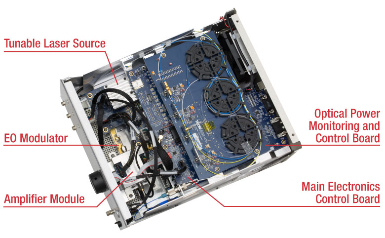
Fiber-Optic Instruments
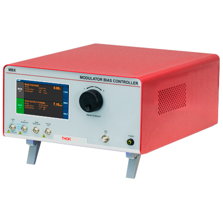
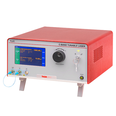
To meet a range of requirements, our fiber-optic instruments span a variety integration levels. Each complete transmitter includes a tunable laser, a modulator with driver amplifier and bias controller, full control of optical output power, and an intuitive touchscreen interface. The tunable lasers, modulator drivers, and modulator bias controllers are also available separately. These instruments have full remote control capability and can be addressed using serial commands sent from a PC.
- Fiber-Optic Transmitters, to 110 GHz
- Linear and Digital Transmitters
- Electrical-to-Optical Converters, to 110 GHz
- Modulator Drivers
- Modulator Bias Controllers
- C- and L-Band Tunable Lasers
Customization options include internal laser sources, operating wavelength ranges, optical fiber types, and amplifier types.
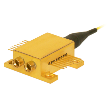
Fiber-Optic Components
Our component-level, custom and catalog fiber-optic products take advantage of our module design and hermetic sealing capability. Products include detectors with frequency responses up to 50 GHz, and we also specialize in developing fiber-optic receivers, operating up to and beyond 40 GHz, for instrumentation markets. Closely related products include our amplifier modules, which we offer upon request, variable optical attenuators, microwave cables, and cable accessories.
- Hermetically-Sealed Detectors, to 50 GHz
- Fiber-Optic Receivers, to 40 GHz
- Amplifier Modules
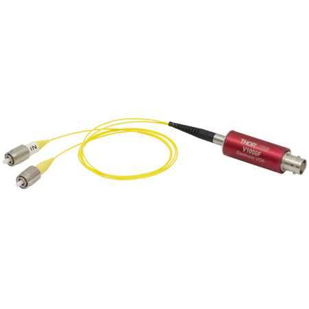
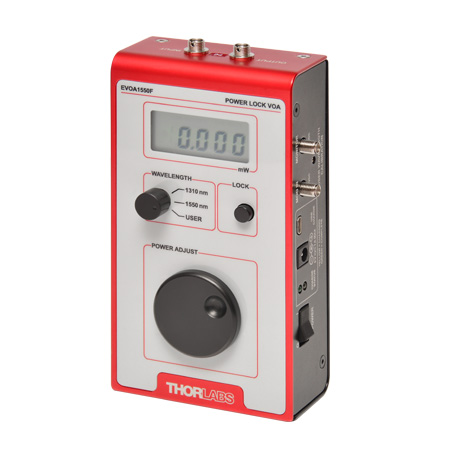
- Electronic Variable Optical Attenuators
- Microwave Cables and Accessories
Customization options include single mode and multimode optical fiber options, where applicable, and detectors optimized for time or frequency domain operation.
Free-Space Instruments
Our free-space instruments include detectors with frequency responses around 1 GHz and pulsed lasers. Our pulsed lasers generate variable-width, nanosecond-duration pulses, and a range of models with different wavelengths and optical output powers are offered. User-adjustable repetition rates and trigger in/out signals provide additional flexibility, and electronic delay-line products enable experimental synchronization of multiple lasers. We can also adapt our pulsed laser catalog offerings to provide gain-switching capability for the generation of pulses in the 100 ps range.
- Pulsed Lasers with Fixed 10 ns Pulse Duration
- Pulsed Lasers with Variable Pulse Width and Repetition Rates
- Electronic Delay Units to Synchronize NPL Series Pulsed Lasers
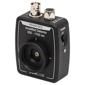
- Amplified Detectors
Customization options for the pulsed lasers include emission wavelength, optical output powers, and sub-nanosecond pulse widths.

| Posted Comments: | |
Robert Carlson
(posted 2024-10-10 09:18:24.717) RX10AF: Does the built-in TIA have an AGC function, or is it a linear TIA ? (We need linear response: i.e. When optical input drops below the sensitivity, the TIA voltage output also drops to a Min level; then immediately provide linear output response when the optical input signal returns. No AGC. tdevkota
(posted 2024-10-11 11:09:52.0) Thank you for reaching out to Thorlabs. The RX10AF does not have AGC. Its TIA is nominally linear. Quantitatively, for a <250 mV output swing it exhibits <2% THD. Alvaro Rosa
(posted 2022-05-09 09:27:37.86) Hello,
From the datasheet it is stated the maximum intput power for 5dBm in a CW.
We would like to use the PD RX10AF to photodetect a signal which has 0dBm of CW, but 27dBm of peak power. Is that possible or the PD will be damaged due to the high optical peak power??
Thank you.
Best,
Álvaro cdolbashian
(posted 2022-06-06 10:40:15.0) Thank you for reaching out to us Alvaro. This peak power you have described would certainly oversaturate, and potentially damage the detector. I have reached out to you directly to discuss your application directly. Alvaro Rosa
(posted 2022-02-22 05:45:29.24) Which is the sensitivity (i.e. the minimum optical power required at the PD input) of the model RX10CF? cdolbashian
(posted 2022-04-13 11:09:10.0) Thank you for reaching out to us Alvaro. The minimum power for these types of devices can be calculated by looking at the NEP spec of the device in our specs tab. Using the NEP, simply multiply your NEP value by Sqrt(measurement bandwidth). I have reached out to discuss this with you as your minimum detectable power will be determined by your experimental instrumentation. |

 Zoom
Zoom| Item # | Full Specs |
Bandwidth | Wavelength Range (Photodiode Material) |
Conversion Gain |
Fiber Pigtail | RF Connector |
Package | Instrument Item #a |
|---|---|---|---|---|---|---|---|---|
| RX10DF | 40 kHz - 10 GHz | 700 - 870 nm (GaAs) | 210 V/W | OM4b (MM) | Female 2.92 mm | 3 Pin | RXM10DF | |
| RX10CF | 700 - 870 nm (GaAs) | 230 V/W | SMF-28c (SM) | RXM10CF | ||||
| RX10BF | 750 - 1650 nm (InGaAs) | 430 V/W | OM4b (MM) | RXM10BF | ||||
| RX10AF | 780 - 1650 nm (InGaAs) | 450 V/W | SMF-28c (SM) | RXM10AF |

 Zoom
Zoom| Item # | Full Specs |
Bandwidth | Wavelength Range (Photodiode Material) |
Conversion Gain |
Fiber Pigtail | RF Connectors |
Package | Instrument Item #a |
|---|---|---|---|---|---|---|---|---|
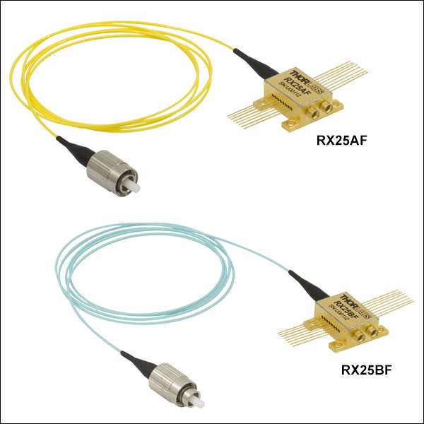
| RX25DF | 500 kHz - 25 GHz | 700 - 870 nm (GaAs) | 60 - 5000 V/W | OM4b (MM) | Differential, Dual GPPO®* |
16 Pin | RXM25DF | |
| RX25BF | 750 - 1650 nm (InGaAs) | 80 - 8000 V/W | OM4b (MM) | RXM25BF | ||||
| RX25AF | 1250 - 1650 nm (InGaAs) | 80 - 8000 V/W | SMF-28c (SM) | RXM25AF |
*GPPO is a registered trademark of Corning.

 Zoom
Zoom| Item # | Full Specs |
Bandwidth | Wavelength Range (Photodiode Material) |
Conversion Gain |
Fiber Pigtail | RF Connectors |
Package | Instrument Item #a |
|---|---|---|---|---|---|---|---|---|
| RX33BF | 45 kHz - 33 GHz | 750 - 1650 nm (InGaAs) | 95 - 3150 V/W | OM4b (MM) | Differential, Dual SMPM (GPPO®* compatible) |
5 Pin | RXM33BF |
*GPPO is a registered trademark of Corning.

 Zoom
Zoom| Item # | Full Specs |
Bandwidth | Wavelength Range (Photodiode Material) |
Conversion Gain |
Fiber Pigtail | RF Connectors |
Package | Instrument Item #a |
|---|---|---|---|---|---|---|---|---|
| RX38AF | 45 kHz - 38 GHz | 800 - 1650 nm (InGaAs) | 75 - 3375 V/W | SMF-28b (SM) | Differential, Dual GPPO®* |
16 Pin | RXM38AF |
*GPPO is a registered trademark of Corning.

 Zoom
Zoom| Item # | Full Specs |
Bandwidth | Wavelength Range (Photodiode Material) |
Conversion Gain |
Fiber Pigtail | RF Connectors |
Package | Instrument Item #a |
|---|---|---|---|---|---|---|---|---|
| RX40AF | 300 kHz - 40 GHz | 1250 - 1650 nm (InGaAs) | 100 - 3650 V/W | SMF-28b (SM) | Differential, Dual GPPO®* |
16 Pin | RXM40AF |
*GPPO is a registered trademark of Corning.

 Zoom
Zoom
| Item # | Full Specs |
Bandwidth | Wavelength Range (Photodiode Material) |
Conversion Gain |
Fiber Pigtail | RF Connectors |
Package | Instrument Item #a |
|---|---|---|---|---|---|---|---|---|
| RX42AF | 45 kHz - 42 GHz | 800 - 1650 nm (InGaAs) | 65 - 2700 V/W | SMF-28b (SM) | Differential, Dual GPPO®* |
16 Pin | RXM42AF |
*GPPO is a registered trademark of Corning.