 Products Home / Active Optical Devices / Electro-Optic Modulators / Lithium Niobate Electro-Optic Modulators, Fiber-Coupled (1260 nm - 1625 nm)
Lithium Niobate Electro-Optic Modulators, Fiber-Coupled (1260 nm - 1625 nm)
- Up to 40 GHz Lithium Niobate (LiNbO3) Modulators
- Fiber-Coupled, High-Speed Modulation
- Intensity, Phase, or I/Q
- X-Cut or Z-Cut Devices
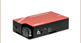
LNP6118
40 GHz Phase Modulator with Polarizer, Z-Cut
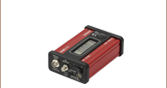
LNA2322
10 GHz Intensity Modulator,
X-Cut
LNLVL-IM-Z
Low Vπ 40 GHz Intensity Modulator, Z-Cut
Enlarged View


Please Wait
Click to Enlarge
Figure 1.2 Z-Cut LiNbO3 Intensity Modulator Cross-Section
Click to Enlarge
Figure 1.1 X-Cut LiNbO3 Intensity Modulator Cross-Section
Features
- Titanium-Indiffused Waveguides
- Low Optical Loss
- Long-Term Bias Stability
- Hermetically Sealed Packaging
- FC/PC Fiber Connectors
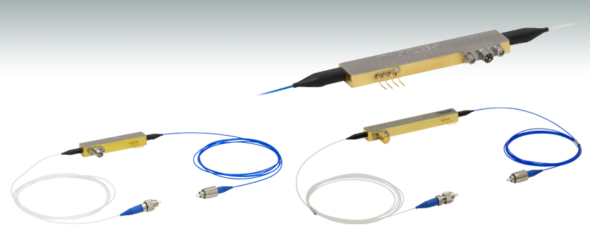
Thorlabs manufactures a variety of lithium niobate (LiNbO3) optical phase, intensity, and I/Q modulators. These high-performance devices are based on titanium-indiffused waveguide technology, offer large bandwidths, and are ideal for developing high-speed modulation systems.
The modulators on this page are fabricated from either X-cut or Z-cut LiNbO3 (see Figures 1.1 and 1.2). X-cut intensity modulators employ a symmetrical design that provides low frequency-chirp in the modulated signal, while Z-cut intensity modulators provide more efficient modulation (i.e., lower Vπ or half-wave voltage) at the expense of higher frequency-chirp. Phase modulators are only offered as Z-cut devices because their single optical path does not benefit from the symmetry of the X-cut design. The I/Q modulator fully exploits the advantages of symmetry as an X-cut device.
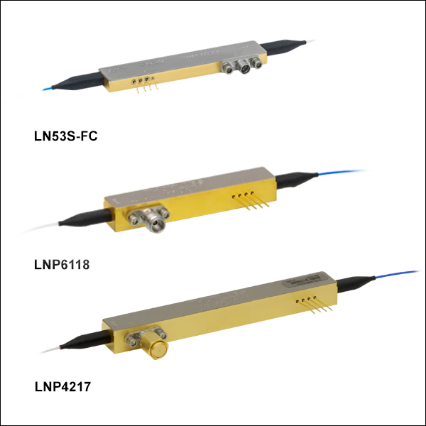
Z-cut devices are also capable of supporting both the ordinary and extraordinary optical modes, which have different modulation efficiencies. An integrated optical polarizer, positioned before the output port of the device, is included in all of our Z-cut intensity modulators and some of our Z-cut phase modulators as only one mode is desirable for most applications. While most applications benefit from the integrated polarizer, the LN53S-FC, LNP6119, and LNP4217 Z-cut phase modulators are offered for applications where the polarizer is undesirable.
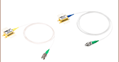
The modulators come with a polarization-maintaining (PM) input fiber pigtail and a single-mode (SM) output fiber pigtail that are terminated with FC/PC connectors. The PM fiber is keyed to the slow axis, which is also aligned to the extraordinary mode of the modulator. Please note that custom options for PM output fiber pigtails and FC/APC connectors are available for all LiNbO3 modulators. For more information on custom configurations (e.g., fiber type, connectors) and quotes, please contact Tech Support.
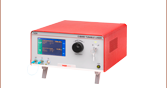
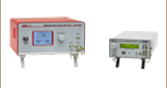
All the fiber-coupled LiNbO3 modulators offered below are compatible with our EO modulator drivers. Our fiber-coupled tunable lasers provide an ideal O-band, C-band, or L-band source for use with these modulators. For all-in-one solutions in high-speed fiber optic test and measurement, we offer reference transmitters, optical transmitter with phase modulators, and calibrated electrical-to-optical converters.
| Maximum Ratings for LiNbO3 Modulators | |
|---|---|
| Optical Input Power | 100 mW |
| Input RF Power | 24 dBm |
| Operating Temperature Range | 0 °C to 70 °C |
| Storage Temperature Range | -40 °C to 85 °C |
Intensity Modulator Specifications
| Item # | LNA2322 | LNA2124 | LNA6213 | LNA6112 | LNLVL-IM-Z |
|---|---|---|---|---|---|
| Optical | |||||
| Operating Wavelengtha | 1525 nm - 1605 nm | 1525 nm - 1605 nm | 1260 nm - 1625 nm | 1525 nm - 1605 nm | 1525 nm - 1605 nm |
| Optical Insertion Loss | ≤5.0 dB (4.0 dB Typ.) | ≤5.0 dB (4.0 dB Typ.) | ≤6.5 dB (5.0 dB Typ.) @ 1310 nm ≤5.5 dB (4.5 dB Typ.) @ 1550 nm |
≤5.0 dB (4.0 dB Typ.) | ≤5.5 dB (4.5 dB Typ.) |
| Optical Return Loss | ≥40 dB | ≥40 dB | ≥40 dB | ≥40 dB | ≥40 dB |
| Optical Extinction Ratio (@ DC, 1550 nm) |
≥20 dB | ≥20 dB | ≥20 dB | ≥20 dB | ≥20 dB |
| Optical Input Power (Extraordinary Mode) | ≤100 mW | ||||
| Optical Input Power (Ordinary Mode) |
≤100 mW | ≤10 mWb | |||
| Electrical (@ 1550 nm) | |||||
| E/O Bandwidth (-3 dB) | ≥10 GHz (14 GHz Typ.) | ≥10 GHz (15 GHz Typ.) | ≥30 GHz (35 GHz Typ.) | ≥30 GHz (35 GHz Typ.) | 10 GHz (Typ.) |
| Operating Frequency Range | DC to 15 GHz (Min) | DC to 15 GHz (Min) | DC to 40 GHz (Min) | DC to 40 GHz (Min) | DC to 40 GHz (Min) |
| RF Vπ (@ 1 GHz) | ≤6.5 V (4.5 V Typ.) | ≤6.5 V (4.3 V Typ.) | ≤6.0 V (5.5 V Typ.) | ≤6.0 V (5.5 V Typ.) | 2.2 V (Typ.) |
| RF Vπ (@ 20 GHz) | - | - | - | - | ≤3.9 V (3.5 V Typ.) |
| RF Vπ (@ 40 GHz) | - | - | - | - | ≤6.0 V (5.0 V Typ.) |
| DC Bias Vπ (@ 1 kHz) | ≤10.0 V (6.5 V Typ.) | ≤15.0 V (13.0 V Typ.) | ≤5.0 V (3.5 V Typ.) | ≤11.0 V (8.5 V Typ.) | ≤11.0 V (9.0 V Typ.) |
| S11 | -12 dB (-10 dB Max), DC to 10 GHz | -12 dB (-10 dB Max), DC to 25 GHz -8 dB (-6 dB Max), 25 to 40 GHz |
|||
| RF Input Power | 24 dBm Maximum | ||||
| Photodetector | |||||
| Reverse Bias Voltage | -5.5 V to -3.0 V | N/A | |||
| Responsivity | 0.1 mA/mW to 0.5 mA/mW | N/A | |||
| Output Optical Power Monitoring Range |
-5 dBm to 10 dBm | N/A | |||
| Mechanical | |||||
| Crystal Orientation | X-Cut | Z-Cut | Z-Cut | Z-Cut | Z-Cut |
| RF Connection | Male SMP (GPO®† Compatible), Full Detent | Female 1.85 mm (V) | Female 1.85 mm (V) | Female 2.92 mm (K) | |
| Fiber Type | Input: PANDA Polarization Maintaining Output: SMF-28®† Single Mode |
||||
| Fiber Lead Length | 1.5 m Typ. | ||||
| Internal Polarizer | N/Ac | Aligned with the Extraordinary Mode of the Chip | Aligned with the Extraordinary Mode of the Chip | Aligned with the Extraordinary Mode of the Chip | Aligned with the Extraordinary Mode of the Chip |
| Environmental | |||||
| Operating Case Temperature | 0 °C to 70 °C | ||||
| Storage Temperature | -40 °C to 85 °C | ||||
Phase Modulator Specifications
| Item # | LN65S-FC | LN53S-FC | LNP6118 | LNP6119 | LNP4216 | LNP4217 |
|---|---|---|---|---|---|---|
| Optical | ||||||
| Operating Wavelengtha | 1525 nm - 1605 nm | 1260 nm - 1625 nm | 1260 nm - 1625 nm | |||
| Optical Insertion Loss | ≤4.5 dB (3.0 dB Typ.) | ≤5.5 dB (5.0 dB Typ.) @ 1310 nm ≤4.5 dB (4.0 dB Typ.) @ 1550 nm |
≤7.25 dB (6.0 dB Typ.) @ 1310 nm ≤5.75 dB (5.0 dB Typ.) @ 1550 nm |
|||
| Optical Return Loss | ≥40 dB | |||||
| Optical Input Power (Extraordinary Mode) |
≤100 mW | |||||
| Optical Input Power (Ordinary Mode) |
≤10 mWb | ≤100 mW | ≤10 mWb | ≤100 mW | ≤10 mWb | ≤100 mW |
| Electrical (@ 1550 nm) | ||||||
| S11 | -12 dB (-10 dB Max), DC to 10 GHz | -12 dB (-10 dB Max), DC to 25 GHz -8 dB (-6 dB Max), 25 to 40 GHz |
||||
| E/O Bandwidth (-3 dB) | 10 GHz Typ. | 35 GHz Typ. | 10 GHz Typ. | |||
| Operating Frequency Range | DC to 15 GHz (Min) | DC to 40 GHz (Min) | DC to 40 GHz (Min) | |||
| RF Vπ (@ 10 GHz) | 6.5 V (Typ.) | 7.0 V (Typ.) | 3.5 V (Typ.) | |||
| RF Vπ (@ 30 GHz) | - | ≤9.5 V (8.5 V Typ.) | ≤5.5 V (4.6 V Typ.) | |||
| RF Input Power | 24 dBm Maximum | |||||
| Low-Frequency Modulator Specifications (@ 1550 nm) | ||||||
| Operating Frequency Range | N/A | DC to 1 MHz (Typ.) | DC to 1 MHz (Typ.) | |||
| Vπ | N/A | 10 V (Typ.) @ 1 kHz | 13 V (Typ.) @ 1 kHz | |||
| Mechanical | ||||||
| Crystal Orientation | Z-Cut | |||||
| RF Connection | Male SMP (GPO®† Compatible), Full Detent | Female 1.85 mm (V) | Female 2.92 mm (K) | |||
| Fiber Type | Input: PANDA Polarization Maintaining Output: SMF-28®† Single Mode |
|||||
| Fiber Lead Length | 1.5 m Typ. | |||||
| Internal Polarizer | Aligned with the Extraordinary Mode of the Chip | N/Ac | Aligned with the Extraordinary Mode of the Chip | N/Ac | Aligned with the Extraordinary Mode of the Chip | N/Ac |
| Environmental | ||||||
| Operating Case Temperature | 0 °C to 70 °C | |||||
| Storage Temperature | -40 °C to 85 °C | |||||
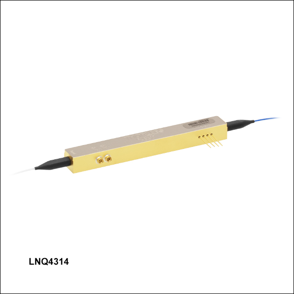
I/Q Modulator Specifications
| Item # | LNQ4314 |
|---|---|
| Optical | |
| Operating Wavelengtha | 1525 nm - 1575 nm |
| Optical Insertion Loss | ≤9.0 dB (7.0 dB Typ.) |
| Optical Return Loss | ≥40 dB |
| Optical Extinction Ratio | ≥20 dB |
| Optical Input Power | ≤100 mW |
| Electrical | |
| S11 | -12 dB (-10 dB Max), DC to 25 GHz -8 dB (-6 dB Max), 25 to 30 GHz |
| E/O Bandwidth (-3 dB) | ≥20 GHz (25 GHz Typ.) |
| Operating Frequency Range | DC to 30 GHz |
| RF Vπ (@ 1 GHz) | ≤7.5 V (6.0 V Typ.) |
| DC Biases Vπ (@ 1 kHz) | ≤10.0 V (8.0 V Typ.) |
| RF Input Power | 24 dBm Maximum |
| Mechanical | |
| Crystal Orientation | X-Cut |
| RF Connections (Two) | Male SMPM (GPPO®† Compatible), Full Detent |
| Fiber Type | Input: PANDA Polarization Maintaining Output: SMF-28®† Single Mode |
| Fiber Lead Length | 1.5 m Typ. |
| Environmental | |
| Operating Case Temperature | 0 °C to 70 °C |
| Storage Temperature | -40 °C to 85 °C |
† GPO, GPPO, and SMF-28 are registered trademarks of Corning Incorporated.
Intensity Modulator Pin Diagrams
Click to Enlarge
LNA2322 10 GHz Intensity Modulator, X-Cut, Pin Diagram
Click to Enlarge
LNA2124 10 GHz Intensity Modulator, Z-Cut, Pin Diagram
Click to Enlarge
LNA6213 40 GHz Intensity Modulator Pin Diagram
Click to Enlarge
LNA6112 Small Form Factor Housing 40 GHz Intensity Modulator Pin Diagram
Click to Enlarge
LNLVL-IM-Z Low Vπ 40 GHz Intensity Modulator Pin Diagram
Phase Modulator Pin Diagrams
Click to Enlarge
LN65S-FC and LN53S-FC 10 GHz Phase Modulator Pin Diagram

Click to Enlarge
LNP6118 and LNP6119 40 GHz Phase Modulator Pin Diagram
Click to Enlarge
LNP4216 and LNP4217 Low Vπ 40 GHz Phase Modulator Pin Diagram
I/Q Modulator Pin Diagram
Click to Enlarge
LNQ4314 25 GHz I/Q Modulator Pin Diagram

Driving an Electro-Optic Phase Modulator with the Amplified Output of a Function Generator
Click to Enlarge
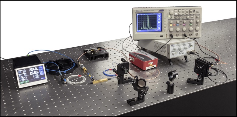
Figure 4.1 Experimental Setup Used to Evaluate Whether a Basic RF Source Built Around a Function Generator Could be Sufficient to Drive a Fiber-Coupled EO Phase Modulator
Thorlabs offers a selection of fiber-coupled electro-optic (EO) modulators, which are ideal for modulating light from fiber-coupled laser sources. Applications frequently require EO modulators to be driven at rates of 1 GHz or higher, which places significant demands on the driving radio frequency (RF) voltage source. We investigated whether it would be possible to use a basic setup built around a function generator to drive a fiber-coupled EO phase modulator. The experimental setup we designed and implemented to test this possibility included instrumentation to record the spectrum of the modulated optical signal. By analyzing the modulated optical spectrum, we confirmed this basic RF source is a viable option for driving a fiber-coupled EO phase modulator. Our approach and results are documented in this Lab Fact.
Experimental Design and Setup
The design of the RF voltage source portion of the setup required first determining the power the RF source should supply to drive the fiber-coupled EO phase modulator. The power requirements were calculated after we made an estimate of the driving voltage needed to achieve the modulation depth desired for this application. Details describing our process for selecting a modulation depth, the relationship between modulation depth and driving voltage, and the calculations we used to estimate the power required from the RF voltage source are included in the Lab Facts document. From our investigations, we determined the power from the function generator alone would not be sufficient for our application. Our solution was to insert a low noise amplifier between the function generator and EO modulator. We also included an electrical low pass filter before the modulator to remove signal distortion that appeared to originate with the function generator. We drove the EO phase modulator with a sinusoidal RF voltage, which imparted a sinusoidal phase modulation on the 1550 nm CW laser signal.
A scanning Fabry-Perot interferometer, whose output was sent to an oscilloscope, was placed after the EO phase modulator and used to measure and monitor the spectrum of the modulated optical signal. It was necessary to use the Fabry-Perot interferometer for this purpose as it has the ability to resolve the very fine spectral features of the phase-modulated optical spectra: at a wavelength of 1550 nm, a frequency difference of 1 GHz is equivalent to a wavelength difference of 0.8 pm. The measured spectra were recorded as functions of scan time. In the Lab Facts document, we describe a straight-forward method to convert from units of Fabry-Perot scan time to units of relative optical frequency. For this work, we estimate Δf = (1.17 GHz/ms)Δt.
Experimental Results
As is described in the Lab Facts document, theory predicts the spectra of our phase modulated optical signals would include sets of symmetric sidebands arranged around the laser carrier peak at frequency fo. The sidebands are displaced from the laser carrier peak frequency at integer multiples of the modulation frequency fm (fo ± Nfm with N = 1, 2, ...). The relative heights of the sidebands are a function of the modulation depth, which is in turn a function of the peak-to-peak value of the RF driving voltage. Given the modulation depth, the relative amplitudes of the laser carrier peak and modulation sidebands can be calculated. This makes it possible to tailor the power distribution across the various peaks to meet an application's needs. We used the predictive power of this model to confirm our RF source was adequately driving the EO modulator.
The spectra shown in Figures 4.2 and 4.4 are representative of the modulation spectra we measured. The theoretical curves in Figure 4.3 are a function of modulation depth and plot the expected relative powers of the laser carrier peak (solid red curve), first order sidebands (dotted blue curve), second order sidebands (dotted green curve), and third order sidebands (dotted violet curve). The black arrow points to the modulation depth corresponding to the spectrum in Figure 4.2, and the gray arrow points to the modulation depth corresponding to the spectrum in Figure 4.4. From our results, we determined our measured and applied modulation frequencies agreed, and we confirmed the spectral power distributions in our optical spectra were consistent with the peak-to-peak driving voltage of the RF source. We conclude that the good agreement between the expected and recorded results validates the use of a basic RF source built around a function generator as a driver for fiber-coupled EO phase modulators.

Click to Enlarge
Figure 4.4 EO Phase Modulator Spectrum When Vpp = 3.63 V
The carrier frequency is fo; the modulation frequency is fm = 1 GHz. The X-axis reports the scanning time of the Fabry-Perot interferometer and can be directly related to the signal's relative frequency spectrum.
Click to Enlarge
Figure 4.3 Curves Relating the Power in the Carrier and Several Sideband Peaks as A Function of Modulatrion Depth
The 0.44 modulation depth indicated by the black arrow corresponds to Figure 4.2, and the 0.56 modulation depth indicated by the gray arrow corresponds to Figure 4.4.
Click to Enlarge
Figure 4.2 EO Phase Modulator Spectrum When Vpp = 2.85 V
The carrier frequency is fo; the modulation frequency is fm = 1 GHz. The X-axis reports the scanning time of the Fabry-Perot interferometer and can be directly related to the signal's relative frequency spectrum.
| Posted Comments: | |
Martin K
(posted 2025-11-17 13:54:08.573) Dear Thorlabs team, I would like to use a single LNQ4314 IQ modulator to modulate several C-band ITU-grid CW lasers simultaneously (all combined and driven with the same electrical signal). However, I expect the bias point of the Mach-Zehnder interferometers and the IQ phase bias to be wavelength-dependent to some degree, limiting the extinction ratio and phase accuracy for some of the channels.
Which bandwidth can I expect in this case? Could you provide typical characterization data over the C-band (e.g. a plot of the three bias points vs. wavelength) for the LNQ4314? jdelia
(posted 2025-11-24 11:10:17.0) Thank you for contacting Thorlabs. You are correct that the bias points will vary with wavelength. Regarding your other inquiries, we have reached out to you directly to discuss your application further. Artur Matoso
(posted 2025-11-05 15:27:27.733) Dear responsible, What is the input impedance of the LNQ4314? I am currently trying to connect a driver board, and I cannot find anywhere whether the modulators are 50 ohm or high impedance. Thank you. ksosnowski
(posted 2025-11-06 09:31:25.0) Hello Artur, and thanks for reaching out to us. Our fiber modulators have low input impedance and it is intended to use a 50 Ohm signal generator to drive these. LNQ4314 has a 32 Ohm termination resistor, so it is normal to see some attenuation compared to driving a 50 Ohm load. Micah Jakulewicz
(posted 2025-09-22 14:23:48.67) Hello ThorLabs,
Would it be possible to get the LNP4216 with PM output fiber. Also do you offer polyimide buffered fiber for the input and output fibers?
Thank you,
Micah tdevkota
(posted 2025-09-23 11:19:45.0) Thank you for contacting Thorlabs. Custom products can be requested by emailing our technical sales team at techsales@thorlabs.com or by using the red "Request Quote" button above. We will discuss the possibility of offering this customization directly. Valliammai A
(posted 2025-08-26 10:56:22.863) Is there any phase modulator you would suggest for working in the DC range? Currently we are using this model LN53S-FC but it doesn't seem to fit for the DC purpose. tdevkota
(posted 2025-08-29 03:42:31.0) Thank you for contacting Thorlabs. The LN53S-FC may not be the right device for your application. The LN53S-FC, like all of our devices, has a DC coupled electrical input to allow the use of broadband signals. However, the power handling limitations, as listed in the Maximum Ratings, constrain the usability of the device in pure DC applications. The LNP6118 and LNP4216 phase modulators include an additional low-frequency phase modulator, in series with the RF phase modulator, that can be controlled through a separate set of pins. This low-frequency modulator section of these devices can support DC signals that are multiple times the typical Vpi. Yongqi Shi
(posted 2024-09-19 14:43:51.073) In the spec of LNP4216, the cut-off EO bandwidth frequency is shown as 10GHz. Is it a mistake? Because this one is also used for up to 40GHz, so I think the cut-off frequency should be around 35GHz? tdevkota
(posted 2024-09-27 02:02:49.0) Thank you for reaching out to Thorlabs. The -3 dB E/O bandwidth of the LNP4216 is 10 GHz. Unlike photodiodes, these devices don't exhibit a steep roll-off after the -3 dB point, making them usable up to 40 GHz (-6 dB). I've reached out to you directly regarding this. david l
(posted 2024-05-14 00:06:34.17) I don't see anywhere in the specs or other documentation for Intensity Modulators what the purpose of the DC Bias input is. How do I know what value to apply? Is it absolutely necessary? Since there is a separate DC bias port is this related or not to a DC offset in the RF input? Should the RF input be AC coupled (DC blocked)? Or can the DC bias (whatever it should be) be part of the RF signal? Again I don't see any charts or explanation of the function of the DC bias port. cdolbashian
(posted 2024-06-04 01:49:05.0) Thank you for reaching out to us with this inquiry. The modulation function for these devices follows a sine curve. Depending on your DC bias, your RF modulation will fall on some part of this sine curve. In order to have maximum amplitude and reach the appropriate modulation, it is important to bias your device appropriately such that you are able to reach the given intensity (or phase) change required. given the input voltage. I have contacted you directly to discuss this further, based on your requirements. Fumihiko Kannari
(posted 2024-03-18 10:47:12.933) I am using a LN65S-FC in a Michelson Interferometry. Light signal must go through the modulator twice in both directions. On the modulator there are "IN" and "OUT" for light direction. What do those mean? ksosnowski
(posted 2024-03-21 01:34:43.0) Hello Fumihiko, thanks for reaching out to Thorlabs. The LN65S-FC is intended as unidirectional. This device may be used bidirectionally to some extent however we cannot guarantee the performance of bias, Vpi, or bandwidth. The output fiber is also SM and it would be critical to align the reverse direction polarization within the SM fiber which would require a paddle polarization controller. I have reached out directly to discuss your application in further detail. Michael Chack
(posted 2024-02-27 23:26:22.7) Hi, I have this LNA2322 modulator. After a long time using it, and it had worked properly, suddenly today I just wondered that it has not any optical output !!! Everything is OK, the bias voltage, the input optical power, the fibers, the connectors, its physical conditions... But it has not optical output. I have never seen this before. (NOTE: At all times, I have followed all safety principles and critical conditions of working with this device.) jdelia
(posted 2024-03-04 11:45:30.0) Thank you for contacting Thorlabs. This appears to be either a fiber break or connector damage. I have reached out to you directly so that we may troubleshoot this device. Desalegn wol
(posted 2024-02-09 09:56:40.207) I recently bought LNA6213 to work at 40GHz. I am wondering what is the voltage required for the modulator to reach 40GHZ? the voltag requirement seems out odf range of the maximum 24 dBm. how to achieve this? cdolbashian
(posted 2024-02-16 03:36:52.0) Thank you for reaching out with this inquiry. Looking at the drive voltage graph on the overview page, we call for ~7.5-8V for the 40GHz drive frequency. As you mention, and as we mention on the page, the maximum input power is 24dBm, which corresponds to 10Vpp. It seems that perhaps you were using RMS voltage when calculating the corresponding voltage to 24dBm? 24dBm for this device corresponds to ~10Vpp which is below what we spec for the driving voltage at 40GHz. I have contacted you directly to discuss this further. Cristian Tong
(posted 2023-11-13 16:27:05.1) Dear sir/madam,
I have a question about the relation between RF driving power, Vpp, and V_pi of LN65S-FC phase modulator. In the product datasheet, it is declared that the half wave voltage V_pi of this modulator is 6.5V. On the other hand, the RF input power is 24dBm, which corresponds to Vpp = 10.02V, which is less than 2V_pi=13V. Is it possible to set the driving voltage between -6.5V to +6.5 V? or the voltage should kept under 5V? It seems there is a problem with the data given in the specs of this product. ksosnowski
(posted 2023-12-05 01:44:38.0) Hello Cristian, thanks for reaching out to Thorlabs. Vpi is defined as peak to peak, so for LN65S-FC using -3.25 V to +3.25 V will result in the full Pi of phase shift. Vpp must still remain below ~10V in order to not exceed the 24dBm RF thermal power limits for sine modulation. I have reached out directly to discuss your application in further detail. Vladimir Zenin
(posted 2023-10-27 11:09:26.903) Hello Thorlabs,
I am thinking to use your intensity modulator to make Q-switch all-fiber laser (with fiber cavity, Er-fiber active medium and 980-nm pump). Therefore I have two questions:
1) The limit on the optical input power (100 mW), does it mean average power or the peak power? In my laser the average power will be low (10-100 mW), but the peak power might be higher than 100 mW
2) What will be if the pump, 980 nm, will go into the modulator? Will it simply go through, or is it better to avoid it?
Thank you in advance! ksosnowski
(posted 2023-11-02 11:46:04.0) Hello Vladimir, thanks for reaching out to Thorlabs. 100mW is our safe operating limit for peak power with these modulators. We recommend avoiding passing the pump wavelength into the modulator as it may result in photorefractive damage. I have reached out directly to discuss this further. Florian Prawits
(posted 2023-10-12 11:20:08.22) Dear employees of Thorlabs,
I have a question regarding the two phase modulators:
LN65S-FC
LN53S-FC
1. Since the input fiber is PM and my laser source is also using a PM (key to slow-axis oriented) fiber, is it even necessary to consider the inline polarizer of the LN65S-FC? Are there any drawbacks to be expected by opting directly for the LN53S-FC?
2. Is it possible to obtain these models with a PM output fiber and/or FC/APC connectors?
Kind regards
Florian Prawits ksosnowski
(posted 2023-10-13 02:13:26.0) Hello Florian, thanks for reaching out to Thorlabs. The inclusion of the polarizer usually depends upon the application. The LN chip itself supports two polarization modes. The optical losses of both modes are similar, but the Vpi’s are quite different. If the laser being used has a low polarization extinction ratio, or the PM orientation is not perfectly aligned, elliptically polarized light could be injected into the modulator. This would allow mixing of the two polarization modes with unintended results. To prevent any the mixing of the polarization modes, a polarizer is inserted in the LN65S modulator. We have offered PM fiber and various connectors and for these requests you can email techsales@thorlabs.com directly. I have reached out directly to discuss your application in further detail. soowoong Lee
(posted 2023-10-06 10:48:54.543) Hi,
I purchased LN65S-FC and plan to use it
In product LNA6112, the relationship between frequency and voltage is shown in a graph
However, in LN65S-FC, I don't know the relationship between input(RF) voltage and output frequency is unknown.
Please tell me the voltage and frequency relationship expressed graphically in product LN65S-FC
Thank you in advance ksosnowski
(posted 2023-10-13 05:45:19.0) Hello Soowoong, thanks for reaching out to Thorlabs. As LN65S-FC is a phase modulator, measuring the exact frequency response as not as straightforward for us compared to an intensity modulator. We only test the response at a couple of discrete frequencies to verify performance rather than run a continuous sweep to obtain S21 data. I have reached out directly to discuss this further. Igor Litvin
(posted 2023-09-18 11:25:21.31) Good day.
We want to buy LNQ4314.
We want to use it for frequency shift arounf 7 GHz.
What exactly extra we have to buy to perfom the experiment?
Regards.
Igor. cdolbashian
(posted 2023-10-19 10:42:31.0) Thank you for reaching out to us with this application-based inquiry. I have contacted you with some details to answer your question. For future application-type inquiries, please reach out to your local tech support team at Europe@thorlabs.com. Chii-Chang Chen
(posted 2023-04-17 15:54:26.057) Dear Sir,
I bought your phase modulator in April 2022 via UNICE E-O SERVICES INC. I saw from the spec that the electrical connector is SMP. I bought a cable with SMP jack from another company. But I cannot plug the cable on the modulator. I do not know if I bought the cable with wrong SMP connector.
You can find the CAD file of the SMP jack cable from the link below https://drive.google.com/file/d/1huIKe3k7ubCnDKACZkKepqcZwhD1zuxK/view?usp=sharing
Please kindly give me an example of the cable with the correct SMP connector.
Many thanks for your help.
Chii-Chang Chen
Professor in National Central University cdolbashian
(posted 2023-04-26 09:48:43.0) Thank you for reaching out to us with this inquiry! Unfortunately, I do not feel safe clicking the cloud download link you provided here. We do, however, have an offering of SMP jacks, and associated mechanical drawings. I have contacted you directly to show you where such documentation lives on our website. Hopefully this will be sufficient for you to ensure compatibility. user
(posted 2023-04-16 16:47:15.28) The extinction ratio of the modulator we obtained at 1550nm light with DC modulation appears too low (Pmax/Pmin~=10). Does it mean that the crystal is faulty. Can you suggest some diagnostic steps?
Also, to make sure, do you express the extinction ratio as 10log(Pmax/Pmin) or as 20log(Pmax/Pmin)? cdolbashian
(posted 2023-04-26 09:51:27.0) Thank you for reaching out to us with this inquiry. We do indeed express the ER as 10log(Pmax/Pmin). I have emailed you directly with some questions, suggestions, and guidelines for the trouble you are seeing. Laurent Pien
(posted 2023-03-22 14:51:23.34) Hello
What are mechanical dimensions of your 10GHz Mach Zehnder component, please?
Thanks in advance ksosnowski
(posted 2023-03-24 03:07:35.0) Hello Laurent, thanks for reaching out to Thorlabs. You can view the mechanical dimensions of LN65S-FC's package in the CAD File under the red document icons on this page. Unfortunately the dimensions of internal components such as waveguides are proprietary. I have reached out directly to discuss this application further. Joseph Izatt
(posted 2022-11-09 16:00:41.527) Hi, since your intensity modulators are based on phase shifting one (or both) of the paths of a Mach-Zehnder interferometer, could you make the other output of the interferometer available so the modulator could function as a very fast 1x2 optical switch? ksosnowski
(posted 2022-11-10 10:56:22.0) Hello Joseph, thanks for reaching out to Thorlabs. Currently this is outside our manufacturing capabilities for the LN modulators. I have contacted you directly regarding this. user
(posted 2022-07-21 16:04:56.407) What is the typical/max Vpi of LN65S-FC @ 1 GHZ? cdolbashian
(posted 2022-07-26 02:40:58.0) Thank you for reaching out with this inquiry. As we do not have specific data for all the Vpi for our full operation range, I have reached out to you to discuss some potential estimates for this value. user
(posted 2022-06-28 18:04:44.22) Hi, Do you have LN65S-FC with lower Vpi option? cdolbashian
(posted 2022-07-06 11:47:58.0) Thank you for reaching out to us with this inquiry. I have contacted you directly with regards to the feasibility of this as a future stock part, and current custom part. Joakim Argillander
(posted 2022-05-18 06:56:45.3) Hi! What is the input impedance of the LN82S-FC and the LN65S-FC? I am currently designing a driver board, and I cannot find anywhere whether the modulators are 50 ohm or high impedance. ksosnowski
(posted 2022-05-23 02:11:31.0) Thanks for reaching out to Thorlabs. LN82S-FC and LN65S-FC have 50 Ohm input impedance. user
(posted 2022-05-17 16:21:47.26) Hi, Do you have 'frequency - Vpi' graph or data for LN65S-FC phase modulator? ksosnowski
(posted 2022-05-23 02:10:19.0) Thanks for reaching out to Thorlabs. At 1 GHz the Vpi would be around 5 V. We do not have Vpi vs frequency plots for the phase modulators as we don’t have an easy way to measure the Vpi at frequencies lower than 10 GHz. At DC we would estimate that it is in the 3-4 V range, DC can be applied to the device but you should note that the maximum RF input power is rated at 24 dBm (~2.8 V DC), and exceeding this can cause the device to fail. user
(posted 2022-03-25 14:29:14.98) What are the DC bias voltage limits? I'd like to know maximum and minimum voltage before applying power to the EOM. cdolbashian
(posted 2022-04-01 02:00:14.0) Thank you for reaching out to us at Thorlabs. We recommend a minimum voltage of 0V, and a maximum of 20V. We have confirmed that 20V is appropriate for operation whereas 35V will damage the device. Unfortunately, at this time we haven't tested between 20-35V. For guaranteed lifetime/performance, I would recommend 20V. stefano chiodini
(posted 2022-02-10 09:17:08.23) Good morning,
I am looking for a phase modulator EOM fiber coupled at 532 nm.
Do you have any?
Thank you in advance,
Stefano Chiodini ksosnowski
(posted 2022-02-15 05:40:45.0) Hello and thanks for reaching out to Thorlabs, custom products can be requested by emailing techsales@thorlabs.com or by using the red "Request Quote" button above. We will discuss the possibility of offering this customization directly. Yazhou wang
(posted 2021-12-16 04:51:13.597) Hello, how can I calculate the minimum pulse duration of the intensity EO modulator? YLohia
(posted 2021-12-23 01:02:41.0) Hello, the minimum pulse duration can be estimated by 1/(maximum bandwidth) of the modulator. Please note that this is an estimate only and not a guaranteed spec as the result can depend on the minimum peak intensity, the drive electronics, and production variations. user
(posted 2021-11-16 23:13:08.41) Hello
I have a question about the LN81S-FC internal photodetector
In the datasheet there is one reverse voltage for the photodiode, what is this? Do I derive this detector with an external separate circuit?!
If the answer is yes, please send me details of the design?
If the answer is No, what is the reverse bias in the data sheet?
Is there any note in photodiode usage or can we connect it directly to an oscilloscope and get data?!
best regards jgreschler
(posted 2021-11-18 10:51:13.0) Thank you for reaching out to Thorlabs. The integrated photodiode is designed to monitor the DC levels of the modulator and can be driven with just a simple DC power supply. The reverse bias specification on the data sheet is applied to the photodiode similar to the products in our DET series. You can read more about this application, including recommended circuit diagrams, here https://www.thorlabs.com/newgrouppage9.cfm?objectgroup_id=9020 Anthony Garzarella
(posted 2021-07-05 01:08:25.52) I am looking for a fiber-coupled EO modulator, like your LN82S-FC, that can be used at 1064nm. It seems that all of your modulators are spec'ed for 1550 nm.
Can you help? YLohia
(posted 2021-07-07 02:59:14.0) Hello, thank you for contacting Thorlabs. Custom products can be requested by emailing techsales@thorlabs.com or by using the red "Request Quote" button above. We will discuss the possibility of offering this customization directly. user
(posted 2021-06-12 12:36:31.3) I would like to reproduce the modulator EO bandwidth (S21) measurement for this modulator. My expectation is that I would sweep the RF input and monitor the output power on an optical power meter.
If I have a single wavelength into a photodiode I obtain half the power at the DC term because of the square law nature of the detector. If I have multiple sidebands, these will beat to produce DC terms and IF terms in the photodiode. In heterodyne systems where I care about the RF I must ensure the photodiode amplifier has the appropriate bandwidth to pass those sidebands.
My question is whether the IF beating terms created from the modulated sidebands are irrelevant to an optical power meter and if only the total DC power is used to determine the incident optical power. In other words, is the optical power meter only concerned with the DC power, or is it necessary to consider any IF generated? How does Thorlabs perform this measurement? Thank you. YLohia
(posted 2021-06-15 11:04:54.0) We make the S21 measurement using a Vector Network Analyzer (VNA). For S21 in our test configuration, Port 1 of the VNA supplies a small-signal, frequency swept source that is coupled into the RF port of the modulator. A voltage is applied to the DC bias of the modulator in order to bias the modulator at quadrature (the half-power point). The optical output from the modulator is coupled into a high-speed photodetector; the bandwidth of the detector should meet or exceed the frequency range of the source. The output of the photodetector is coupled into Port 2 of the VNA, which measures the received signal. The response of the photodetector will need to be removed from the VNA measurement in order to get the response of the modulator (for Thorlabs’ ultrafast photoreceivers (https://www.thorlabs.com/navigation.cfm?guide_id=2558), a file with the response data for a specific device is available upon request). Jim Zhang
(posted 2021-05-24 12:21:30.1) From specifications, it seems this product is for 1500 - 1600 nm wavelength application. My interest is at 1064 nm. Do you have similar product for 1064 nm wavelength applications? YLohia
(posted 2021-05-24 02:13:51.0) Thank you for contacting Thorlabs. I have reached out to you directly regarding this. mogendi Mogendi
(posted 2021-05-06 19:58:31.46) With show of diagrams, explain how intensity modulator functions, specifically
LiNbO 3 modulator. YLohia
(posted 2021-05-07 10:45:35.0) The lithium niobate intensity modulator is controlled by applying a voltage to the RF input. This directly changes the refractive index of the lithium niobate waveguide via the electro-optic effect. It is a Mach Zehnder Interferometer configuration, so the relative phase between the two arms of the MZI results in controllable constructive and destructive interference. This is how the intensity is changed.
The input fiber is PM, so it is required to have the polarization aligned with the slow axis of the fiber to operate correctly. The source should be around 1550nm.
The voltage required to switch between max signal level and minimum is called Vpi. Equivalently it is the voltage to cause a relative phase shift of pi radians in the MZI. The units are set to be biased around the middle of the negative slope. What this means is that, to reach about a maximum signal level, the user should apply –Vpi/2. To reach a minimum, the user should apply +Vpi/2. The bias point can also be separately adjusted with two of the pins on the package.
The remaining two pins on the package are for photodiode feedback. The photodiode signal is low when the output into fiber is maximized. The photodiode signal is high when output into fiber is minimum. This is simply a direct connection to the photodiode, so it should be considered a current source. The current has to be detected by traversing some load resistance and measuring the voltage across the resistance. Typical current levels are uA to low mA range.
More information, including diagrams and equations, can be found in online literature or in textbooks. Markus Schmidt
(posted 2021-05-01 18:44:45.22) Hello, I read the datasheet of LN81S-FC. in page 2 you wrote "field replaceable smp connector" for it's RF connector. what do you mean about field replaceable ?
Is that mean we can replace it with another RF connector? YLohia
(posted 2021-05-03 01:59:59.0) Hello, thank you for contacting Thorlabs. The "field replaceable" connector is intended to be changed with another RF connector of the same type by the end-user in the event there is some damage to the existing connector. Michael S
(posted 2021-03-24 05:41:54.99) Hello,
The specs of the phase modulators state that the max input power is 24 dBm, consequently the maximum V_p2p should be 10 V. This in turn limits the achievable modulation depth, given that the typical V_pi is 7V. I am asking to verify that I have read and understood the specs correctly in order to respect the power limitations of the device.
Thanks a lot. YLohia
(posted 2021-03-25 10:53:43.0) Hello, thank you for contacting Thorlabs. Yes, your understanding here is correct -- the modulation depth will be limited by the 24 dBm max RF power (10.02 Vpp) and the Vpi spec of your device. william B
(posted 2021-03-18 15:46:45.29) I am using a LN86S-FC. I observe much higher insertion losses (18db) when biased for max throughput. This test datasheet states a measured insertion loss of 5db. I have checked the input polarization and ensured it is aligned for maximum output power. What other things should I check? I am interested in buying more units, but I need to solve the excess loss issue first. Thanks in advance for your help. YLohia
(posted 2021-03-29 02:43:20.0) Hello, thank you for contacting Thorlabs. Based on the description of the problem, it appears that there may be an issue with the fiber/connector. Please inspect the two fiber connectors under a fiberscope for damage and use a (low power) fiber fault tester to check for breaks along the length of the input and output fibers. Preeti Yadav
(posted 2021-02-09 05:25:29.177) Hello!
For our quantum key distribution setup, we want to inquire about the electro-optic phase modulator to achieve polarization control. Can the phase modulator be used to generate one of the four polarization states, say, linearly diagonal states at 45 degrees and -45 degrees, and circularly polarized states, left and right, upon inputting a linearly polarized light at 45 degrees to the modulator. At the moment we require the modulation frequency to be around 100 MHz, is that a possibility with the 10 GHz phase modulators?
Thank you! YLohia
(posted 2021-03-15 03:34:56.0) Hello, thank you for contacting Thorlabs. In theory, without the polarizer in the LN65S-FC (so the correct part number being LN53S-FC), you could use the modulator as a polarization controller. That being said, these modulators are not optimized for such applications and we wouldn't be able to spec performance. Additionally, there would be significant drift. Please also note that the output fiber is a regular single mode fiber, which is not designed to maintain any specific polarization state. Van Rudd
(posted 2020-12-29 19:38:47.09) You have a nice plot showing how V_pi varies with frequency for the intensity modulators, but not the phase modulators. Do you have that data?
Also, from what is listed on the spec page it looks like the intensity modulator has a lower V-pi than the phase modulator. Why is this?
Thanks. YLohia
(posted 2021-01-15 02:08:45.0) Unfortunately, we do not have plots of the EO Frequency Response for the Phase Modulators as this is not an easy measurement to make for Phase Modulators because an external interferometer is needed to characterize this data. The Vpi is different in the intensity and phase modulators because they have fundamentally different structures. The biggest difference is layout of the optical waveguides (the intensity modulator layout allows for a push-pull configuration, see the diagrams in the Overview section of this page). There are also other aspects of the device design that can affect the Vpi. bo-Hun choi
(posted 2020-07-22 01:30:45.28) Hi
I purchased a couple of your product "LN82S-FC" and am doing experiment. I want to use bias controller for LN82S because of the condition change as time. I wonder that the pin3 and 4 can be used for this purpose. Are these pins alive for this purpose?
I am looking forward to hearing from you
Adam YLohia
(posted 2020-07-22 09:37:20.0) Hello Adam, thank you for contacting Thorlabs. Yes, Pins 3 & 4 are intended to be used for DC bias control. You may use our MBX bias controller for such an application. user
(posted 2020-06-09 12:14:14.403) Does this device come with loose tube 900 micron or tight buffer 900 micron fiber? YLohia
(posted 2020-06-09 02:43:00.0) Thank you for contacting Thorlabs. We use tight buffer fibers for these devices. Zichao Zhou
(posted 2020-03-04 22:58:45.923) Hi
I am a Ph.D student in University of Ottawa. I am planning to buy a single side band modulator. Here I have a few questions about this IQ modulator.
I want to use this IQ modulator as a single side band modulator. I am wondering how should I give a RF frequency to this modulator. Should I give the the two frequency with exact 90 degree phase shift if I want to use it as a single side band modulator. How can I apply this frequency if I only have one radio frequency generator.
Another question is that would the single side band modulator shift the original optical frequency to a lower frequency or a higher frequency. Can I control the direction of the frequency shifting.
Looking forward to your reply.
Thank you!
Regards
Zichao asundararaj
(posted 2020-03-06 10:08:07.0) Thank you for contacting Thorlabs. I have reached out to you via email with this information. Il-Bum Kwon
(posted 2020-02-03 03:26:15.293) When I modulate the light with sinusoidal pattern using LN81S-FC, Is it necessary to control bias voltage of LN81S-FC? This modulator will experience temperature change.
If I need to control bias control to compensate the temperature effect, then what should I do?
Can you support any electric board to control bias voltage? YLohia
(posted 2020-02-03 11:52:42.0) Thank you for contacting Thorlabs. We do recommend using a bias controller for the intensity modulators, especially for applications where the ambient temperature will be unstable. We offer the MBX bias controller for this. user
(posted 2019-12-23 21:54:52.6) too expensive YLohia
(posted 2019-12-26 04:16:51.0) Thank you for your feedback. We are sorry to hear that you find our lithium niobate modulators too expensive. If you are looking to use this in an OEM application and/or are looking to purchase a large quantity, please email us at Sales-TQE@thorlabs.com to discuss volume pricing. Alexey Kokhanovskiy
(posted 2019-12-01 23:40:37.953) Dear Sir/Mme
Could you recommend a controller for bias voltages applied to IQ modulator DC bias input ports?
With respect,
Alexey Kokhanovskiy llamb
(posted 2019-12-04 04:35:36.0) Hello Alexey, thank you for contacting Thorlabs. We do not have a recommended bias voltage controller for the LN86S-FC; a controller that meets our DC Bias voltage specs will suffice. Muhammad Adeek
(posted 2019-09-16 19:36:09.46) Dear Representative,
I want to purchase an optical modulator that must support 10GHz pulses for setting up the Phase-OTDR system. Kindly guide me which out of the three models (LN82S-FC, LN81S-FC, LN53S-FC) are suitable in my case? YLohia
(posted 2019-09-16 03:01:35.0) Hello, thank you for contacting Thorlabs. The first two are intensity modulators while the third is a phase modulator. I have reached out to you directly to discuss your application further. gregory.gaeumann
(posted 2018-08-31 11:52:53.037) Hello, I would like to use your 10 GHz Phase modulator to generate large phase modulations (for serrodyne frequency shifting). Unfortunately, the maximal RF input power is limited to 24 dBm, which is quite low. Is this limit really critical or does it only lead to a slow warm-up of the device? In case it is critical, can you tell me the limiting factor? Thank you. llamb
(posted 2018-09-07 11:21:10.0) Thank you for contacting Thorlabs. We have only qualified these devices up to 24 dBm for the RF input power and for lifetime testing. The primary limiting factor is the termination circuit that utilizes thin film resistors. These resistors should be able to handle higher power levels if the device is properly heat sunk. I will reach out to you directly to discuss your application and some limitations further. mchen
(posted 2018-05-22 15:06:44.77) Hello,
If using LN66S-FC or LN27S-FC at 1064nm, how high the insertion loss roughly will be?
Thanks,
Mike YLohia
(posted 2018-05-22 04:54:09.0) Hello Mike, thank you for contacting Thorlabs. At 1064 nm, while these modulators can technically be used, the waveguides will definitely not be single mode; they will be multi-mode due the cut-off wavelength being specified at 1290-1450 nm. The insertion loss, modulation efficiency (Vpi), extinction ratio, etc. will all change considerably from the values that we specify at 1550nm. Unfortunately, we have not performed testing outside of the specified operating wavelength range. hnguyen43
(posted 2018-05-07 11:00:34.96) Can this modulator work for the wavelength range between 1100-1180nm? If not, can you customize an intensity modulator for that wavelength range? YLohia
(posted 2018-05-09 10:29:58.0) Thank you for contacting Thorlabs. At 1100-1180 nm, while these modulators can technically be used, the waveguides will definitely not be single mode; they will be multi-mode due the cut-off wavelength being specified at 1290-1450 nm. The insertion loss, modulation efficiency (Vpi), extinction ratio, etc. will all change considerably from the values that we specify at 1550nm. Unfortunately, we are unable to offer a custom GHz modulators based on wavelength range at the moment. jlpeng
(posted 2018-03-09 08:26:35.26) This is not phase and intensity modulator, but phase or intensity modulator. I need an integrated phase and intensity modulator with compact package, i.e. a modulator can change the phase and the amplitude of input light signal. Do you have such kind of modulator(PM fiber pigtailed, bandwidth DC-10 MHz)? YLohia
(posted 2018-03-16 10:17:22.0) Hello, thank you for contacting Thorlabs. Are you looking to control the phase and intensity independently or simultaneously? The LN86S-FC is the only modulator we currently offer that can be used to modulate the intensity and phase of light simultaneously (but not independently) with the proper biasing and drive signals. This may require fairly complex drive and bias control depending on the desired output. This style of modulator has been used for advanced telecommunication modulation schemes (for example, 16-QAM). If you wish to control the intensity and phase independently using our parts, you will have to cascade two different intensity and phase modulators. cristhian_alex19
(posted 2018-02-20 12:20:49.237) Hello! Please tell me what would be the optimal voltages that should enter the iq modulator from the BIAS,to work as a phase or intensity modulator in the LN86-S modulator? YLohia
(posted 2018-04-09 05:47:34.0) Hello, thank you for contacting Thorlabs. I will reach out to you directly to get more details about your application to better answer your question. akg
(posted 2018-01-31 22:22:19.57) Hello,
I am looking for a setup which looks like:
SFL1550P --->
LN82S-FC (or LN81S-FC) --->
LN53S-FC
Please suggest if there will be issues in above interconnections. Specifically input of LN53S-FC is polarization maintaining while the output of LN82S-FC is not. Please comment on this and contact me as I wish to proceed quickly.
Atul tfrisch
(posted 2018-02-06 10:04:01.0) Hello Atul, thank you for contacting Thorlabs. You will need to be sure that the SM fiber of LN82S-FC launches the light aligned to the PM ax is of LN53S-FC. This could be achieved with a fiber polarization controller. Alternatively, we are able to offer LN82S-FC with a PM fiber on both the input and output. I will reach out to you directly to discuss which of these options is more suitable for your application. jason.a.willis99
(posted 2018-01-04 14:32:16.553) Could you please send me the application note for this product? tfrisch
(posted 2018-01-04 03:06:47.0) Hello, thank you for contacting Thorlabs. I will send you the application note as well as a link to our Lab Fact presentation which has some information on driving modulators which may be relevant to these amplitude modulators as well as the phase modulators used in the experiment. arjan.meskers
(posted 2017-07-21 15:50:31.39) The description states "PM input fiber pigtail and a SM output fiber pigtail." PM fibers are by definition single mode (i.e. SM), however SM fibers are not by definition polarization maintaining.
It is not clear to me if the output fiber is also polarization maintaining, this also holds for the product '10 GHz Intensity Modulator, Zero Chirp'.
Could you clarify the type of output fiber? tfrisch
(posted 2017-07-26 01:11:34.0) Hello, thank you for contacting Thorlabs. The input fiber is polarization maintaining as the modulation will only occur for one linear input state. The output will be modulated, but since a single mode (and not PM) fiber is used, the polarization of the modulated signal can vary with stress and bends in the fiber. We can offer versions that have PM fibers on both sides as a custom if you need. I will reach out to you directly as well. user
(posted 2017-07-21 07:25:06.81) For the phase and intensity modulators you should offer them with FC/APC connectors and/or not connectorized as depending on the system they will be used in the reflection from the end face of the connector will cause feedback. tfrisch
(posted 2017-07-26 01:44:08.0) Thank you for contacting Thorlabs. We can offer these connectorized according to your needs. Please email TechSupport@Thorlabs.com for a quote. benjamin.haylock2
(posted 2017-05-04 15:46:46.647) Is it safe to solder the DC pins? nbayconich
(posted 2017-05-22 09:43:08.0) Thank you for contacting Thorlabs. The pins on our Lithium Niobate Intensity Modulators are intended to be soldered. A Techsupport representative will contact you directly. nasertrus
(posted 2017-03-21 08:43:05.833) Hello!
How to manage optical modulator LN82S-FC?
It have SMP connector and 4 pin? What I must do to modulate input signal?
Sorry, but I can't find this information in the Manual. tfrisch
(posted 2017-03-30 05:10:52.0) Hello, thank you for contacting Thorlabs. I see you have already been in contact with a member of our Technical Support Team about the pin diagrams and operation techniques. mlaroton
(posted 2017-03-15 08:24:51.667) Hi, do your 10 GHz intensity modulators (LN82S-FC, or LN81S-FC) include a built-in polarizer? We plan to use them in a double pass setup with a reflection upon a faraday mirror so it is crucial that both polarizations can circulate through the device.
Thank you very much,
Miguel tfrisch
(posted 2017-03-15 09:38:00.0) Hello, thank you for contacting Thorlabs. While these modulators do not have internal polarizers, they are sensitive to polarization. Furthermore, they are not fully bidirection, and performance would be very limited in the reverse direction. I will reach out to you directly with details. yingwah.wu.civ
(posted 2016-09-27 18:14:56.25) Can LN65S-FC be used for transceiver pair for delay line purpose?
Thanks, jlow
(posted 2016-10-05 02:06:00.0) Response from Jeremy at Thorlabs: I will contact you directly about your application. saranha1001
(posted 2016-07-12 10:44:28.417) What is the polarization dependent loss of this product? I couldn't find it in the spec. user
(posted 2016-06-20 15:38:57.803) Hello,
What is the phase transition in this modulator?
Is it standard 2 state 180 deg. or it's controlled by RF signal bias? besembeson
(posted 2016-06-22 09:23:40.0) Response from Bweh at Thorlabs USA: No it is not a two state modulator. The phase is controlled by the RF signal input. user
(posted 2016-06-20 13:02:19.567) Hello,
It seems like my int. modulator react only for increasing slope of modulating RF signal (3,5-4,5V, 0-15Mhz, square signal). (Modulated signal is similar to triangles).
I would like to ask, is it too low rf signal frequency, or maybe this modulator feature is to react only
for that slope? But if yes, then how to demodulate logical 0 ? besembeson
(posted 2016-06-22 09:12:51.0) Response from Bweh at Thorlabs USA: Please contact me at techsupport@thorlabs.com to further discuss your application. yue.s
(posted 2016-05-19 06:06:14.71) What is the max input optical power for the intensity modulator LN82S-FC? moreover is the RF and DC voltage mentioned in the spec are the average value or the peak value? besembeson
(posted 2016-05-19 04:11:36.0) Response from Bweh at Thorlabs USA: We recommend keeping the input power to under 100mW. That is the RMS voltage. stefano.minardi
(posted 2015-11-19 12:45:30.847) Dear Sirs,
In order to select the RF driver I should use for the NL05-FC amplitude modulator at 30GHz, I would need the RF input power in dBm. Could you please provide this value?
Thank you and best regards
Stefano Minardi besembeson
(posted 2015-11-20 11:48:33.0) Response from Bweh at Thorlabs USA: If you are using a sinusoidal signal, with the 10V peak to peak maximum input voltage, the maximum RF power you would need will be about 24dBm. In practice you would not need up 10V (especially if you only need half-wave) so the power will be lower than this. tbarrett
(posted 2014-01-08 13:37:44.233) Does this product have a users manual? jlow
(posted 2014-01-09 04:08:34.0) Response from Jeremy at Thorlabs: The LiNbO3 modulators come with a characterization sheet with a drawing showing the pin-outs of the modulators. There's no user manual but I will send to you an application note for your reference. blwpgs
(posted 2013-07-29 11:49:45.217) Hello!
Please tell me what the nominal the bias voltage at the modulator LN05S-FC? (DC Bias Voltage)
On your website I can not find this information. In the Data datasheet does not say anything about the bias voltage (minimum, maximum). Please let me know in what range are the data voltage.
Best regards, Alex. jlow
(posted 2013-08-01 10:31:00.0) Response from Jeremy at Thorlabs: The modulator is set to be on the negative slope when used with 0V bias. However, one would generally use a feedback loop to control the DC bias voltage to minimize DC drift. The DC bias voltage range should be -8V to 8V. tcohen
(posted 2012-12-28 13:06:00.0) Response from Tim at Thorlabs: This is a Mg doped LiNbO3 crystal. This material will form color centers when exposed to light at 780nm, causing higher loss. This is temporary as charge carriers become displaced and trapped in defects, forming dipoles within the crystal, and may be removed by heating. For modulation, there are suitable RF amplifiers available from companies such as SHF, Triquint, Oki, Inphi, Centellax, Picosecond, etc. We will contact you directly to discuss your application in more detail. gnishi
(posted 2012-12-17 00:46:58.797) Dear Sir: I have a question on the modulator.
(1) Can it be used for the modulation with 780nm wavelength? If so, is there any problem with such wavelength region or anything to concern for the opearation?
(2) Do you have a product for driving this modulator?
Thank you for advance. jlow
(posted 2012-10-25 11:40:00.0) Response from Jeremy at Thorlabs: The typical Vpi is about 9-10 Volts at 30GHz. The maximum voltage is 14Vp-p for frequencies > 30GHz and about 10Vp-p for frequencies < 30GHz. Therefore the 2pi phase modulation at 30GHz exceeds our normal maximum RF power (the limiting factor is the power handling capability of the internal termination). We might be able to provide a customized option for higher RF powers at high frequencies. I will get in contact with you directly regarding this possibility. sz292
(posted 2012-10-19 11:54:56.99) hi,
I am about to buy one 40GHz Phase Modulator, I am wondering what is the maximum phase modulation it can reach? is 2pi possible? bdada
(posted 2012-03-21 18:02:00.0) Response from Buki at Thorlabs to ok:
Thank you for participating in our feedback forum. We have contacted you to discuss your application to make sure the LN66S modulator is suitable and to provide additional support.
Please note that the "Overview" and "Specs" tab on this web page provide the specifications you requested. ok
(posted 2012-03-18 13:12:14.0) Whom it may concern,
Sir,
I am a regular purchaser of your products. Now we need some device to spread the spectrum of our optical pulse (output of semiconductor laser; 10ns-pulses with 100Hz-rep.rate and max.power near of 1W). Looks like LN66S is good for this purpose. It is a quite new issue for me, so I need to know some questions:
- how much is maximum applicable RF Drive Voltage?
- is negative value of RF Drive Voltage acceptable or it should be positive pulses only?
- is some DC Bias necessary or we can operate without it?
- could you give a definition of of Insertion Loss Variation? Do you mean optical losses?
Would you be so kind as to answer it?
Thank you in advance,
Oleg Kulagin
Senior Scientist
Institute of Applied Physics tcohen
(posted 2012-02-28 11:36:00.0) Response from Tim at Thorlabs: The LN27 and LN66 are high-speed phase modulators. A single device imparts pure phase modulation on the optical carrier. In that sense they can be considered as frequency shifters as energy is transferred from the optical carrier into the modulation sidebands. However, this is probably not the frequency shifting that you had in mind, as all energy is transferred symmetrically to +/- sidebands around the carrier -- it is not true frequency shifting. If you want to shift the energy from the optical carrier into just one modulation sideband, this type of modulation is called single-side band suppressed carrier (SSB-SC) and the LN86 is the appropriate device for this. By proper DC biasing each of the Mach-Zehnders and phasing of the RF drive signals SSB-SC can be obtained. This acts as a true frequency shifter and the amount of frequency shift is determined by the RF modulation frequency. I have contacted you directly with some more information. a.j.h.meskers
(posted 2012-02-28 07:40:37.0) Dear Sir/Madam,
In the specifications of product LN27S-FC is stated that this device could also shift the optical frequency. How does this exactly work? Could you give me some more information regarding this frequency shifting operation?
Kind regards,
Arjan Meskers bdada
(posted 2011-11-01 12:37:00.0) Response from Buki at Thorlabs:
Thank you for your feedback. Our production team will review your suggestion. Please contact TechSupport@thorlabs.com if you would like to discuss your application further. user
(posted 2011-10-31 12:57:03.0) Please look at adding a SMA to SMP connector as you sell SMA cables but not SMP. jjurado
(posted 2011-06-15 09:54:00.0) Response from Javier at Thorlabs to jikim: Thank you very much for contacting us. At the moment, we do not have the capability to offer such a product. Free-space modulators do not have the capability to achieve 40 dB extinction ratio performance, and producing a fiber coupled LN-type modulator with free-space output would require a significant amount of development. Alternatively, we could supply a short length of PM fiber at the output pigtail, which could be then fitted with a collimator. However, we cannot commit to a 40 dB PER specification. I will contact you directly to get more details about your application. jikim
(posted 2011-06-14 15:17:06.0) Could you provide a customized phase modulator with a PM input (FC/APC) and a free space collimated output to obtain the linear polarization output with extinction ratio more than 40 dB and without ellipticity? In the fiber output there exists thermal effects. jikim
(posted 2011-03-08 16:13:26.0) Is a zero chirp intensity modulator (LN56S-FC) with a PM fiber in the output available? I would appreciate if you could send me a quotation for it. user
(posted 2011-02-13 22:03:34.0) jjurado
(posted 2011-02-07 10:26:00.0) Response from Javier at Thorlabs to jikim: Thank you very much for submitting your inquiry. The LN53S does not rotate polarization. However, it functions as a variable waveplate, just like a Soleil-Babinet Compensator, when a voltage is applied to the modulator. The voltage changes the relative retardance between two orthogonal polarization modes. No intensity modulation would be observed if the input polarization is perfectly linear *and* if the linear polarization is launched on-axis to the PM input fiber. It is possible that the input polarization is not linear and/or not launched on axis to the modulator.
Small misalignments between the PM fiber and LN crystal will create a small intensity modulated signal when passed through a linear analyzer. Also, use of single mode fiber at the output will allow the amplitude of the intensity modulated signal you observed to vary; just gently press on the fiber. The LN65S modulator, with an internal polarizer, will greatly suppress the undesired intensity modulation. If you need to retain the state of polarization at the output of the modulator, PM output fiber should be used. Also, this modulator can be supplied with FC/APC connectors. jikim
(posted 2011-02-04 17:31:35.0) I have a question on the output polarization of the phase modulator.
A simple experiment has been performed. A single mode laser beam with linear polarization passes through a LN53S-FC modulator to which a sinusoidal signal at few tens of MHz is applied. The output of the modulator passes through a linear polarizer, i.e. a polarization analyzer. A photo diode (PD) observes the intensity of the transmitted beam through the polarizer. Then I could observe the same sinusoidal signal at the PD indicating that the output polarization of the modulator is varied with respect to the phase modulation. Such polarization variation of the output is absolutely not desirable in my application.
When a PM fiber is used in the output port of the phase modulator instead of a SMF, is there any polarization change depending on the phase modulation? Or is there any suggestion from you to escape such a polarization change? jjurado
(posted 2011-02-02 11:54:00.0) Response from Javier at Thorlabs to jikim: Thank you very much for submitting your inquiry. We can certainly provide an LN65S-FC modulators with PM input and output fiber pigtails. I will contact you directly with pricing and lead time information. jikim
(posted 2011-02-02 16:14:34.0) Could you provide a LN65S-FC with PM fibers in both input and output ports? Thorlabs
(posted 2010-10-19 19:23:08.0) Response from Javier at Thorlabs to jikim: There are some slight differences between the x-cut (LN56/LN81) and z-cut (LN63/LN82) 10G intensity modulators, but the variation in the Vpi of the RF port is typically in the following range: DC to 1 GHz = 5V, 3GHz = 5.5V, 10 GHz = 7V. Note, the Vpi @ DC quoted in the specification sheet is for the DC bias port - not the RF port. The Vpi of the RF port is tested and specified with a 10Gb/s pseudo-random bit sequency (PRBS) which has a frequency spectrum that is roughly equivalent to a fixed frequency in the 3-4 GHz range, that is why the Vpi @ 3 GHz above is indicated as being equivalent to the Vpi for the 10 Gb/s PRBS. jikim
(posted 2010-10-19 11:00:14.0) According to the specification, the Vp is mentioned to be in the range of 3 to 8 V. Could you show the frequency dependence of such a voltage on the frequency (from 0 to 10 GHz)? Thorlabs
(posted 2010-10-11 17:47:13.0) Response from Javier at Thorlabs to jikim: We can certainly quote a special FC/APC version of the LN53S-FC. I will contact you directly with more information. jikim
(posted 2010-10-11 13:02:11.0) Is it possible to make FC/APC instead of FC/PC connector of this phase modulator (LN53S-SC)? Thorlabs
(posted 2010-10-07 15:08:16.0) Response from Javier at Thorlabs to Andres: I will contact you directly to discuss your application. We have to first consider your lasers wavelength and power output, among other parameters. andres.aragoneses
(posted 2010-10-07 11:57:04.0) Dear sir/madam
I need an optic amplifier that multiplies the intensity of one laser an integer number of times (2, 3 or 4).
Which is the product I need?
thank you
Aragoneses Adam
(posted 2010-05-06 16:24:13.0) A response from Adam at Thorlabs: We are working on getting these drawings on the web. In the meantime, if you need the drawings please email techsupport@THorlabs.com and we will provide with the necessary documentation. user
(posted 2010-05-05 21:38:35.0) can you please provide mechanical drawings for those products? |

 Zoom
Zoom
Click to Enlarge
Figure G1.1 This operational diagram of an intensity modulator shows the waveguide (blue lines) splitting into two paths embedded in the surface of the lithium niobate (green). The input light is first affected by the modulating RF drive voltage and then the DC bias voltage, as shown by the translucent regions.
Applications
- RF-Over-Fiber (RFOF) and Microwave Photonics
- High-Speed Telecommunications
- WDM Transmission
LiNbO3 optical intensity modulators use a Mach-Zehnder interferometer structure to allow modulation of the optical output power of the device, as shown by Figure G1.1. The devices include two electrical ports: one for the modulation driving signal and one for biasing the modulator. X-cut or Z-cut devices are available. Each modulator has field-replaceable RF input connectors.
X-cut devices allow for both arms of the Mach-Zehnder interferometer to be symmetrically modulated. This symmetry ensures that the modulated output is not also shifted in phase/frequency (chirped).
Z-cut devices have an inequality in the push-pull phase shift between the two arms of the Mach-Zehnder interferometer. This results in a phase/frequency shift (chirp) in the output in addition to the intensity modulation. Z-cut devices also have a better overlap of the electrical and optical fields in the Mach-Zehnder structure, resulting in higher drive efficiencies.
The LNA2322 10 GHz modulator includes an integrated photodetector for optical power monitoring and modulator bias control, eliminating the need for an external fiber tap.
Thorlabs offers three high-speed intensity modulators that can operate up to 40 GHz. The LNA6213 modulator is a high bandwidth device designed to provide up to 40 GHz of modulation over the 1260 nm to 1625 nm operating range. The LNA6112 modulator provides similar performance as the LNA6213, but in the 1525 nm to 1605 nm wavelength range and has a small form factor housing that is 105.0 mm wide compared to the 135.0 mm housings of the other high-speed intensity modulators. The LNLVL-IM-Z modulator provides the lowest RF Vπ, or half-wave voltage, at any specific frequency over the operating frequency range. Figures G1.2 and G1.3 show a typical drive voltage (Figure G1.2) and electro-optic response (Figure G1.3) over the operating frequency range for these modulators. See the Specs tab for complete specifications.
Click to Enlarge
Figure G1.2 Typical Drive Voltage as a Function of Frequency for Our 40 GHz Intensity Modulators
Click to Enlarge
Figure G1.3 Electro-Optic Response as a Function of Frequency for Our 40 GHz Intensity Modulators

 Zoom
Zoom
Click to Enlarge
Figure G2.1 This operational diagram of a phase modulator shows the waveguide (blue line) as one through optical path embedded in the surface of the lithium niobate (green). The input light is affected only by the modulating RF drive voltage, as shown by the translucent region.
Applications
- Chirp Control for High-Speed Communications
- Coherent Communications
- Optical Sensing
LiNbO3 optical phase modulators consist of a single, through optical waveguide, as shown by Figure G2.1. As there is only one optical path to modulate, all of the phase modulators are Z-cut devices in order to optimize drive efficiency. Each modulator has field-replaceable RF input connectors.
The LN65S-FC and LN53S-FC phase modulators provide up to 10 GHz of modulation over the 1525 nm to 1605 nm operating range. The LNP6118 and LNP6119 modulators are high bandwidth devices that provide up to 40 GHz of modulation over the 1260 nm to 1625 nm range.
The LNP4216 and LNP4217 phase modulators provide lower RF Vπ, or half-wave voltage, over the operating frequency range compared to the LNP6118 and LNP6119 modulators. The typical drive voltage of the LNP421x modulators is 3.5 V at 10 GHz and 4.6 V at 30 GHz, compared to the LNP611x modulators that have typical drive voltage of 7.0 V at 10 GHz and 8.5 V at 30 GHz. These devices can be operated at frequencies up to 40 GHz over the 1260 nm to 1625 nm range.
The LNP6118, LNP6119, LNP4216, and LNP4217 devices incorporate an additional low-frequency phase modulator, in series with the RF phase modulator, that can be controlled through a separate set of pins (see the Specs and Pin Diagrams tabs for details).
When only one mode is desired, the LN65S-FC, LNP6118, and LNP4216 modulators include an internal polarizer that is aligned with the extraordinary mode of the chip. For applications that require access to both the ordinary and extraordinary modes, the LN53S-FC, LNP6119, and LNP4217 Z-cut phase modulators are offered without an integrated polarizer.

 Zoom
Zoom
Click to Enlarge
Figure G3.1 This operational diagram of an I/Q modulator shows the waveguides (blue lines) split into four paths embedded in the surface of the lithium niobate (green). The input light is first affected by each MZI's modulating RF drive voltage (RF1 or RF2), and then by each MZI's DC bias voltage (DC1 or DC2), as shown by the translucent regions.
- Dual, Parallel MZIs on a Single X-Cut Lithium Niobate Chip
Applications
- Coherent Communications, Including QAM, QPSK, and DQPSK Encoding
- Single Side Band Suppressed Carrier (SSB-SC) Transmission
LiNbO3 I/Q modulators use a dual-parallel Mach-Zehnder interferometer (MZI) structure in order to allow modulation of both the phase and amplitude of light for advanced optical transmission schemes. As shown in Figure G3.1, the modulator consists of two independently-controlled MZIs whose outputs are combined. The combining structure also includes a bias electrode that applies a phase delay between the two MZIs, allowing for the required phase control between the two modulator arms.
In a QPSK application, this device will allow for a 50 Gb/s link transmission rate. Two I/Q modulators can be used together in a polarization-multiplexed arrangement to double the transmission rate, e.g. two LNQ4314 devices can provide a 100 Gb/s link on the same optical channel/wavelength.