 Products Home
Piezo-Based Fiber Phase Shifters
- Shift the Phase of Light Up to 6.5λ (13π radians) or 27.5λ (55π radians)
- Wavelength Ranges from 1260 to 1625 nm
- Models with Ultra-Low Insertion Loss (<0.05 dB Without Connectors)
- SM and PM Fiber Options
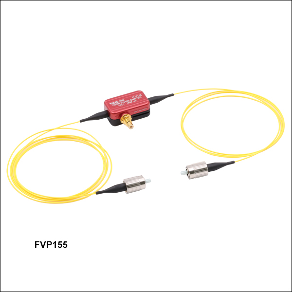
FVP155
1310 - 1550 nm
SM, FC/PC
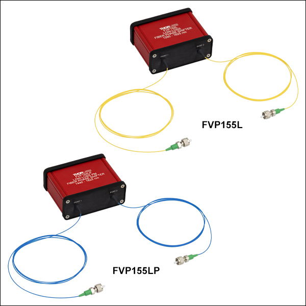
FVP155L
1260 - 1625 nm
SM, FC/APC
FVP155LP
1440 - 1625 nm
PM, FC/APC


Please Wait
Features
- Phase Shifts Up to 6.5λ (13π Radians) or 27.5λ (55π Radians)
- Input Drive Frequencies Up to 20 kHz
- Models for Input Wavelengths from 1260 to 1625 nm
- Use in Closed- or Open-Loop Configurations
- SM and PM Fiber Options for Low-Loss Phase Shifters
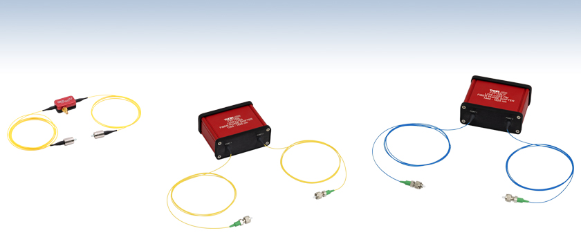
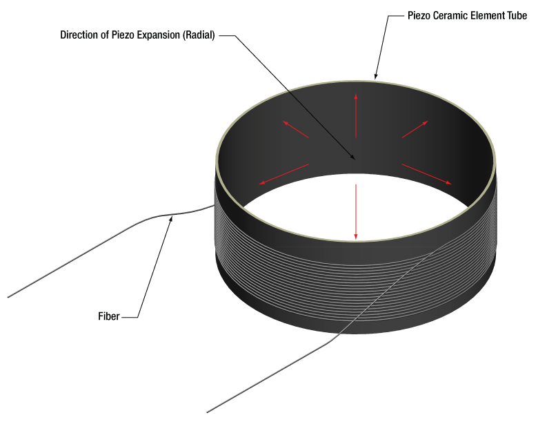
The FVP155, FVP155L, and FVP155LP Piezo-Based Fiber Phase Shifters alter the optical phase of light by stretching the fiber going through the devices. For the FVP155, the fiber is fixed to both ends of a piezoelectric ceramic, which elongates and thus stretches the fiber via the piezoelectric effect (see Figure 1.1). For the FVP155L and FVP155LP, the fiber is wrapped around a piezoelectric tube, which elongates the fiber as the tube expands radially (see Figure 1.2). The coil configuration allows for larger phase shifts by integrating longer sections of fiber, while minimizing the insertion loss by ensuring a low-bend-loss architecture. Please see the Graphs tab for typical graphs of the phase stroke versus the input voltage (Figures 3.1 and 3.4) and the phase stroke versus frequency (Figures 3.2 and 3.5). Our phase shifters are offered with FC/PC (narrow-key) connectors (Item # FVP155) and FC/APC connectors (Item #s FVP155L and FVP155LP).
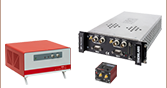
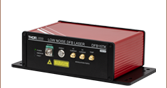
These phase shifters can be controlled by many of Thorlabs' piezo controllers via the SMC input on the devices. For a list of compatible controllers and their bandwidths, see Table 4.1 in the Controller Selection Guide tab. All phase shifters are also equipped with a thermal switch to prevent damage to the device under high temperatures.
Fiber phase shifters are versatile devices with applications in numerous fields. By precisely controlling and modulating the phase of the input optical signal, they enable high-precision measurements, sensing, and laser technologies. Figure 1.3 shows a schematic for integrating the FVP155 into a fiber interferometer to stabilize the path length.
For piezo-based fiber phase shifters with custom wavelength ranges please contact Tech Sales.

Click to Enlarge
Figure 1.3 Our Piezo-Based Fiber Phase Shifters can be integrated into a fiber interferometer to stabilize the path length using a KPC101 K-Cube® piezo controller. FOC = Fiber Optic Coupler, PC = Polarization Controller, PD = Photodetector.
Click to Enlarge
Figure 1.2 Schematic of the FVP155L and FVP155LP Low-Loss Piezo-Based Fiber Phase Shifters

Click to Enlarge
Figure 1.1 Schematic of the FVP155 Piezo-Based Fiber Phase Shifter
| Table 2.1 Phase Shifter Specificationsa | |||
|---|---|---|---|
| Item # | FVP155 | FVP155L | FVP155LP |
| Drive Voltage Range | 0 - 150 V | 0 - 150 V | |
| Phase Stroke at 150 V and 1 kHzb | 13π radians ± 15% | 55π radians ± 20% | |
| Half-Wave Voltage | <11 V | 2.73 V ± 20%b | |
| Capacitance | 200 nF ± 15%c | 48 nF ± 15%d | |
| Resonant Frequencye | 80 kHz ± 15% | >20 kHz | |
| Insertion Loss | <0.1 dB (Without Connectors) | <0.05 dB (Without Connectors)b | |
| Residual Amplitude Modulation | <0.15% | - | |
| Polarization Dependent Lossb | - | <0.01 dB | - |
| Polarization Extinction Ratiob | - | - | >18 dB |
| Operating Wavelength | 1310 - 1550 nm | 1260 - 1625 nmf | 1440 - 1625 nmf |
| Electrical Connector | SMC Male | SMC Male | |
| Fiber Type | SM1550P | SMF-28 Ultra | PM1550-XP |
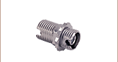
| Fiber Connectors | FC/PC Narrow Key (2.0 mm) | FC/APC Narrow Key (2.0 mm) | |
| Operating Temperature | 0 to 50 °C | 0 to 50 °C (Non-Condensing) | |
| Storage Temperature | -40 to 85 °C | -40 to 80 °C | |
| Dimensionsg (L x W x H) | With Fiber: 2000.0 mm x 28.2 mm x 12.0 mm (78.74" x 1.11" x 0.47") Housing With SMC Connector: 29.0 mm x 28.2 mm x 12.0 mm (1.14" x 1.11" x 0.47") Housing Only: 29.0 mm x 17.0 mm x 12.0 mm (1.14" x 0.67" x 0.47") |
Housing With Connectors: 85.1 mm x 89.4 mm x 34.3 mm (3.35" x 3.52" x 1.35") Housing Only: 85.1 mm x 66.5 mm x 34.3 mm (3.35" x 2.62" x 1.35") |
|
| Table 2.2 FVP155 Phase Shifter Recommended Voltage Limitsa | ||
|---|---|---|
| Frequency | Voltage Limit | Phase Shift |
| 2.0 kHz | 150 V | 14π radians |
| 2.5 kHz | 105 V | 11π radians |
| 3.5 kHz | 90 V | 10π radians |
| 5.0 kHz | 75 V | 9π radians |
| 8.0 kHz | 60 V | 8π radians |
| 11.0 kHz | 55 V | 7π radians |
| 15.0 kHz | 50 V | 6π radians |
| 20.0 kHz | 45 V | 4π radians |
Performance Graphs
Phase shifter performance graphs are typical at 25 °C, unless otherwise stated.
Click to Enlarge
Click for Raw Data
Figure 3.1 Typical FVP155 Phase Shifter Phase Stroke Versus Input Voltage at 1550 nm, Measured With a 2 kHz Input Modulation Frequency
Click to Enlarge
Click for Raw Data
Figure 3.3 Sample data for FVP155 Phase Shifter Half-Wave Voltage Versus Frequency at 1550 nm. The data shown is representative and may vary from device to device.
Click to Enlarge
Click for Raw Data
Figure 3.2 Sample data for FVP155 Phase Shifter Phase Stroke Versus Frequency at 1550 nm. The data shown is representative and may vary from device to device.
Click to Enlarge
Click for Raw Data
Figure 3.4 Typical FVP155L and FVP155LP Phase Shifter Phase Stroke Versus Input Voltage at 1550 nm, Measured With a 1 kHz Input Modulation Frequency
Click to Enlarge
Click for Raw Data
Figure 3.5 Sample data for FVP155L and FVP155LP Phase Shifters Phase Stroke Versus Frequency at 1550 nm. Recommended operating range is from 0 to 20 kHz, shaded in blue. The data shown is representative and may vary from device to device.
| Table 4.1 Phase Shifter Controller Selection Guide | |||||||
|---|---|---|---|---|---|---|---|
| Item # | Channels | Bandwidth | Voltage Range | Maximum Current | FVP155 Suggested Bandwidtha | FVP155L(P) Suggested Bandwidthb | Recommended Cable |
| BPC301 | 1 | 10 kHz (1 µF Load, 1 Vpp) | 0 - 150 V | 0.5 A | 3 kHz (150 Vpp) 26 kHz (30 Vpp) |
8 kHz (150 Vpp) 15 kHz (80 Vpp) |
PAA100 or PAA101 |
| BPC303 | 3 | 1 A | 3 kHz (150 Vpp) 30 kHz (30 Vpp) |
8 kHz (150 Vpp) 15 kHz (80 Vpp) |
|||
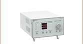
| MPZ601 | 2 | 10 kHz (1 µF Load, 1 Vpp) | 0 - 75 V DC (Software) | 0.5 A | 10 kHz (75 Vpp) 26 kHz (30 Vpp) |
10 kHz (75 Vpp) 15 kHz (50 Vpp) |
|
| 0 - 90 V DC (External Input) |
8 kHz (90 Vpp) 26 kHz (30 Vpp) |
8 kHz (90 Vpp) 15 kHz (50 Vpp) |
|||||
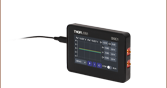
| KPC101 | 1 | 1 kHz (1 µF Load, 1 Vpp) | 0 - 150 V | 0.012 A | 0.09 kHz (150 Vpp) 0.6 kHz (30 Vpp) |
0.5 kHz (150 Vpp) 2.5 kHz (30 Vpp) |
|
| MDT694B | 1 | 9 kHz (No Load, Small Signal) 8.5 kHz (No Load, 150 Vpp) 200 Hz (1.4 µF Piezo, 150 Vpp)c |
0 - 150 V | 0.06 A | 0.6 kHz (150 Vpp) 3 kHz (30 Vpp) |
2.5 kHz (150 Vpp) 13 kHz (30 Vpp) |
CA26XX Series |
| MDT693B | 3 | ||||||
| BPA100 | 1 | See the Responsivity Curves on the Overview tab of the BPA100 Amplifier webpage | 0 - 150 V | 2.5 A | 20 kHz (150 Vpp) 30 kHz (30 Vpp) |
15 kHz (150 Vpp) | CA26XX and T4004 |
 (1)
(1)
| Posted Comments: | |
Ely Eastman
(posted 2025-08-21 16:59:31.75) Hello,
I am curious how long the fiber enclosed in the device is.
Best,
Ely jdelia
(posted 2025-08-22 08:00:31.0) Thank you for contacting Thorlabs. The fiber is fixed at both ends of the piezoelectric ceramic in a stretched state, with a total length of 2000 mm. The length of the fiber enclosed in the device is equal to the housing (~29 mm). |

 Zoom
Zoom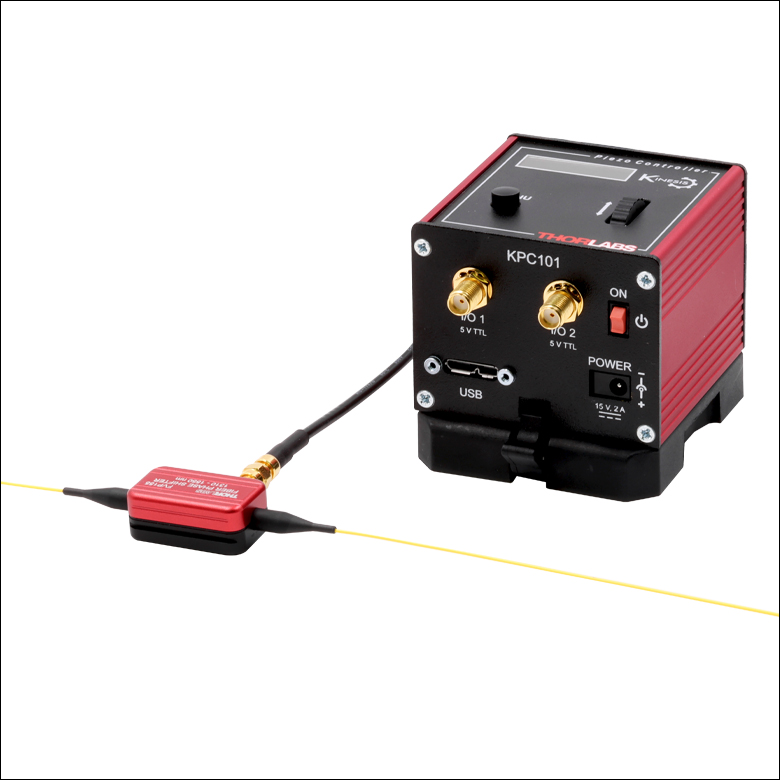
- Phase Shifts Up to 6.5λ (13π Radians)
- Input Wavelength Range:1310 to 1550 nm
- FC/PC Narrow Key Connectors
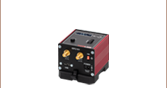
The FVP155 phase shifter can produce a phase stroke of about 6.5λ (13π) at 150 V and operates with input frequencies as high as 20 kHz while maintaining a phase stroke of at least λ (2π). Note that the connectors on the device are narrow key FC/PC (2.0 mm) and that the device can be clamped to an optical table using a CL6 clamp, if needed.
The FVP155 phase shifter is also equipped with a thermal switch to prevent damage to the device under high temperatures. When the device overheats, the circuit will be broken, and it will automatically reconnect when the temperature drops to around 50 °C. Since the device heats up faster when modulated at higher frequencies, we provide a list of recommended maximum voltages as a function of frequency to prevent overheating in Table 2.2 in the Specs tab, for reference.

 Zoom
Zoom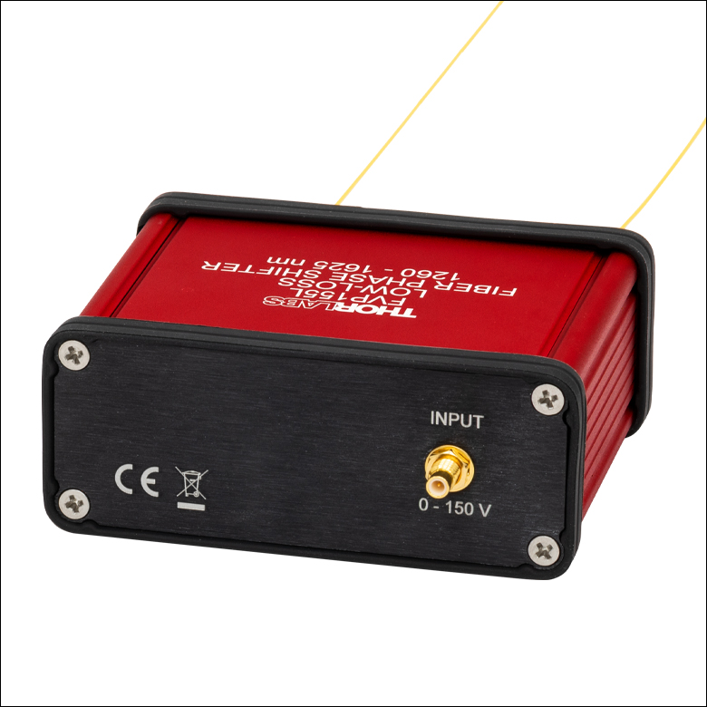
Click to Enlarge
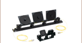
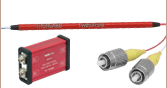
Figure G2.1 The FVP155L and FVP155LP include an SMC connector for an external controller.
- Phase Shifts Up to 27.5λ (55π Radians)
- Input Wavelength Ranges:
- FVP155L: 1260 to 1625 nm, SM
- FVP155LP: 1440 to 1625 nm, PM
- Ultra-Low Insertion Loss of <0.05 dB (Without Connectors)
- Compact Housing
- FC/APC Narrow Key Connectors
The FVP155L and FPV155LP low-loss phase shifters can produce a phase stroke of about 27.5λ (55π) at 150 V and operates with input frequencies as high as 20 kHz. The high phase shift allows for fine and coarse tuning, and the narrow resonant frequency enables the user to drive the device up to 20 kHz with stable temperatures. These are fiber-coil-based devices that, by maintaining a large fiber bend radius, can offer very low insertion losses of <0.05 dB and are well-suited for quantum computing applications such as fiber link stabilization.
The FVP155L uses SMF-28 Ultra fiber with an operating range of 1260 nm to 1625 nm and offers a low polarization dependent loss (<0.01 dB), suitable for applications where input light polarization can vary. The FVP155LP uses PM1550-XP fiber with an operating range of 1440 nm to 1625 nm and offers >18 dB polarization extinction ratio for applications that require maintaining a linear light polarization throughout the fiber setup.