 Products Home
Gain Flattening Filters
- Flatten Gain Spectrum of O-Band Fiber Amplifiers or Erbium-Doped Fiber Amplifiers
- Compatible with PDFA100 Series or EDFA100x Series Amplifiers
- Available in SM and PM Versions
GFFP13
SM Gain Flattening Filter
GFFE15P
PM Gain Flattening Filter


Please Wait
Click to Enlarge
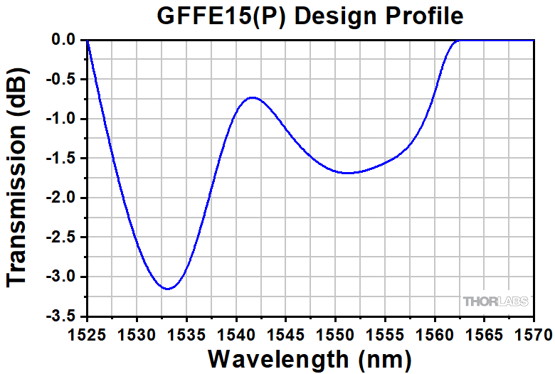
Gain Flattening Filter Design Profile of GFFE15(P)
Click to Enlarge
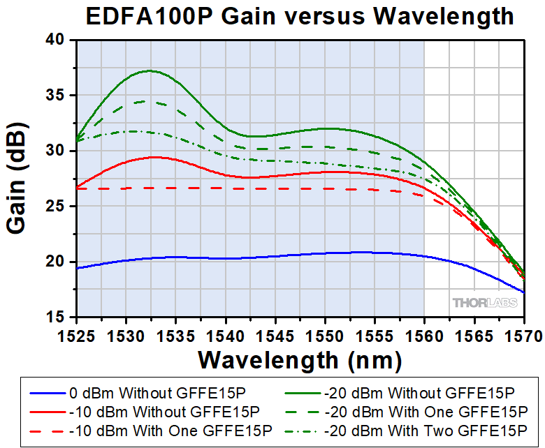
The typical gain of the EDFA100P amplifier without and with the GFFE15P gain flattening filter with different input powers. The blue-shaded region indicates the gain-flattening wavelength range. The filter is optimal for a -10 dBm input power; the gain flatness improves from ~3 dBm (solid red line) to <0.5 dB with the filter (dashed red line). The gain flatness at -20 dBm input power has more variation without the filter (solid green line). While gain flatness can be improved with one filter (dashed green line), cascading two filters further flattens the signal (dashed-dotted green line). The gain spectrum with 0 dBm input power (solid blue line) cannot be further improved with the filter.
Features
- Flatten Gain Spectrum of PDFA100(X) O-Band Fiber Amplifiers or EDFA100x Series Erbium-Doped Fiber Amplifiers
- Operating Wavelength Range
- GFFP13: 1270 nm - 1330 nm
- GFFE15(P): 1525 nm - 1570 nm
- Optimized for -10 dBm Input Power
- Available in SM and PM Versions
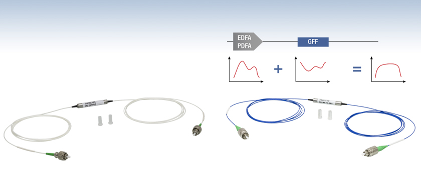
Thorlabs' Gain Flattening Filters are designed for use with the PDFA100(X) O-band fiber amplifiers or the EDFA100x series erbium-doped fiber amplifiers (EDFAs). The filter for the PDFA100(X) amplifiers is offered in SM fiber. The filters for the EDFA100x series are offered in SM (Item # GFFE15) and PM (Item # GFFE15P) models that are compatible with the EDFA100S and EDFA100P amplifiers, respectively. These filters are intended to be connected to the output port of an EDFA or PDFA and are designed to flatten the gain spectrum of the amplifier by adding additional signal loss to the wavelengths where the gain is higher, making them ideal for applications that require equal gain across a wide spectrum. The gain spectrum of the fiber amplifiers depends on the input power level with the gain variations increasing over the operating wavelength range as the input power is decreased. The design transmission curve for each filter, given in the specs table below, flattens the gain of the PDFA100(X) or EDFA100 series at -10 dBm input power.
One of the key specifications for the gain flattening filter is the peak-to-peak error function, which is defined as the difference between the measured transmission curve (in dB) and the design transmission curve (in dB). Each filter will have a transmission profile that deviates from the design curve to some level, and the error function captures this variation over the wavelength range. The peak-to-peak error function is a single valued specification defined as the difference between the maximum error function and the minimum error function. That value in dB is given in the specs table below.
A plot given in the table below, or seen in the Graphs tab, shows the typical PDFA100(X) amplifier gain versus wavelength for three different input power levels (0 dBm, -10 dBm, and -20 dBm). The GFFP13 filter is is designed to provide optimal gain flatness at a -10 dBm input power level, with an improvement from ~8 dB without the filter to <1 dB after the filter over the 1278 - 1328 nm wavelength range. Similarly, the gain flatness at -20 dBm input power is also improved over the same wavelength range. The gain spectrum of the PDFA100(X) amplifier for 0 dBm input power has greater flatness than the design power of -10 dBm, so the GFFP13 filter overcorrects the spectrum leading to a similar flatness level.
The plot to the lower right shows the typical EDFA100P amplifier gain versus wavelength for three different input power levels (0 dBm, -10 dBm, and -20 dBm). The GFFE15(P) filters are designed to provide optimal gain flatness at a -10 dBm input power level, as seen in the sample gain plot to the lower right. The gain flatness at -10 dBm input power over the 1525 - 1560 nm wavelength range is improved from ~3 dB without the filter to <0.5 dB after placing the GFFE15P filter. Similarly, the gain flatness at -20 dBm input power can be improved from ~8.5 dB to <6 dB over the same wavelength range by adding the filter. The gain at -20 dBm can be further improved by cascading two filters to achieve of flatness of <4 dB as shown in the plot to the right. When connecting two filters together, we recommend using either a ADAFC3 or ADAFCPM2 narrow key FC/APC fiber optic mating sleeve, which are suitable for SM and PM fibers, respectively. The gain spectrum of the EDFA100P amplifier for 0 dBm input power level exhibits good flatness and cannot be further improved using these filters.
| Item # | GFFP13 | GFFE15 | GFFE15P |
|---|---|---|---|
| Wavelength Range (Click for Design Profile) |
1270 nm - 1330 nma | 1525 nm - 1570 nmb | |
| Insertion Lossc | <0.8 dB | <0.8 dB | |
| Peak-to-Peak Error Function | <0.6 dB | <0.5 dB | |
| Polarization-Dependent Loss | <0.1 dB | <0.1 dB | - |
| Extinction Ratio | - | - | 20 dB |
| Return Loss | >50 dB | >50 dB | |
| Connector Type | FC/APC | FC/APC | |
| Fiber Type |
SMF-28 In White Ø900 μm Tubing |
SMF-28 In White Ø900 μm Tubing |
PM1550-XP In Blue Ø900 μm Tubing |
| Compatible Amplifier | PDFA100(X) | EDFA100S(X) | EDFA100P |
| Amplifier Gain vs Wavelength |  |
 |
|
Gain Flattening Filter for PDFA100(X) O-Band Amplifiers

Click to Enlarge
This is the design profile for the GFFP13 gain flattening filter, which has been designed to flatten the gain of the PDFA100(X) amplifier at -10 dBm input power. The design is based on averaged gain spectra of multiple PDFA units. Individual PDFA units can exhibit slightly different gain spectra which can result in some deviation from ideal response.

Click to Enlarge
The average gain response of the PDFA100(X) amplifier with and without the GFFP13 gain flattening filter for different input powers. The blue-shaded region indicates the gain-flattening wavelength range. The filter is optimal for a -10 dBm input power; the gain flatness improves from ~8 dB (solid red line) to <1 dB with the filter (dashed red line). The gain flatness at -20 dBm input power is also improved as shown above. The gain spectrum with 0 dBm input power (solid blue line) is overcorrected by the filter, yielding a similar flatness level (dashed blue line).
Gain Flattening Filters for EDFA100x Series Erbium-Doped Fiber Amplifiers
Click to Enlarge
This is the design profile for the GFFE15(P) gain flattening filter, which has been designed to flatten the gain of the EDFA100x series of amplifiers at -10 dBm input power.
Click to Enlarge
The typical gain of the EDFA100P amplifier without and with the GFFE15P gain flattening filter with different input powers. The blue-shaded region indicates the gain-flattening wavelength range. The filter is optimal for a -10 dBm input power; the gain flatness improves from ~3 dBm (solid red line) to <0.5 dB with the filter (dashed red line). The gain flatness at -20 dBm input power has more variation without the filter (solid green line). While gain flatness can be improved with one filter (dashed green line), cascading two filters further flattens the signal (dashed-dotted green line). The gain spectrum with 0 dBm input power (solid blue line) cannot be further improved with the filter.
| Posted Comments: | |
| No Comments Posted |