Constant Current USB-Controlled LED Driver
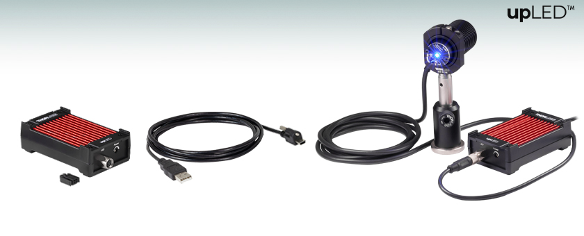
- Driver for Mounted, Fiber-Coupled, and Collimated LEDs
- Maximum LED Current: 1.2 A
- LED Current Accuracy: ±(1% + 10 mA)
- Controlled with USB
- Ideal for OEM Applications
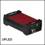
UPLED
USB LED Driver with a Power Supply Adapter and a USB Type-A to Mini-B Cable
Application Idea
An M490L4 Mounted LED Driven with the UPLED Driver

Please Wait
| LED Controller Selection Guide | ||||||
|---|---|---|---|---|---|---|
| Type | Max Number of LEDs |
Max Current |
Modulation Mode |
USB | Remote Operation | Compatible LEDs |
| upLED™ LED Driver | 1 | 1.2 A | N/A | Yes | Yes | Mounted, Collimated, Fiber Coupled, Diffuse Backlight, and PCB Mounteda |
| Compact T-Cube™ Driver | 1 | 1.2 A | 0 - 5 kHz | No | No | |
| 4-Channel Driver | 4 | 1 A | 0 - 100 kHz | Yes | Yes | |
| 4.0 A LED Driver | 1 | 4.0 A | 0 - 5 kHz | Yes | Yes | |
| Solis® LED Driver | 1 | 10 A | 0 - 1 kHz | No | No | High Power |
| High-Power Touchscreen Driver | 1 | 10.0 A | 0 - 250 kHz | Yes | Yes | High Power, Mounted, Collimated, Fiber Coupled, Diffuse Backlight, and PCB Mounteda |
Click to Enlarge
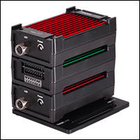
The connection channels help create a stable stack, which can include either the upLED (red housing) or upTEMP (green housing) devices. The stack can also be mounted to an optical table or breadboard using the upBASE base plate.
Click to Enlarge
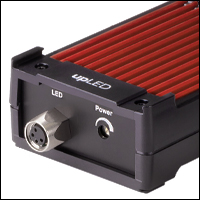
Connection channels at the corners of the upLED housing are included for easy stacking of modules.
Click to Enlarge
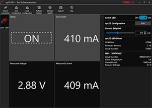
The main upSERIES software GUI displays the LED status and set current, as well as the voltage and current as measured by the upLED.
Features
- Constant Current LED Driver with USB 2.0 Interface
- Internal Memory for Operation without USB Connection
- Includes a Potentiometer for Current Adjustment
- Reads Current Data Stored in the LED EEPROM
- Compact Form Factor with Stacking Capability
- USB 2.0 Type-A to Mini-B Cable with Locking Screw Included
- Requires a 12 V, 1 A Power Supply
- Recommended Item #: DS12 (Sold Below)
- Includes upSERIES® Software
- User-Friendly Software GUI
- Drivers for LabVIEW®, CVI, C, C++, and C# Programming Environments
- Base Plate for Mounting to Optical Tables and Breadboards Available Separately (Sold Below)
Thorlabs' upLED™ LED Driver is a compact, USB-controlled driver for use with Thorlabs LEDs that feature an M8 x 1 circular connector. This constant-current driver can be controlled manually with a linear potentiometer (see Front & Back Panels tab) or through the included upSERIES software, making it ideal for both laboratory and factory environments.
Each upLED driver controls a single LED. To retain the compact footprint (86.7 mm x 52.5 mm) of a single unit while controlling several LEDs, the upLED housing has been designed with connection channels at the corners, which help create a stable assembly of devices. The upLED can also be conveniently stacked up with a upTEMP™ multichannel USB temperature logger to monitor temperature. The two devices feature the same stackable housing and can be simultaneously controlled using the upSERIES Software interface.
The upLED driver, as well as a stack of upSERIES devices, can be securely mounted to an optical table or breadboard using the upBASE Base Plate (see below for details). Note that the base plate extends the footprint of the driver to 86.7 mm x 70 mm.
Power Supply
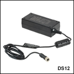
A 12 V, 1 A power supply is required to operate the upLED driver. We recommend the DS12 power supply (sold below). Each upLED driver ships with an adapter cable for use with the DS12 power supply.
Alternatively, a user-assembled power supply may be used. Each driver ships with a power supply adapter, into which the user can insert two 0.5 mm2 wires that provide at least 1 A at 12 V. This adapter plugs into a receptacle on the rear panel that is shown in the Front & Back Panels tab. To protect against polarity reversal of the power supply and adapter connections, the upLED features input polarity protection; the upLED will not be destroyed, but it will not drive the connected LED.
Please note that while the upLED can draw some power from the USB connection, this is only used to operate the microprocessor, which enables the software GUI to show whether a power supply is available and to read out data from the connected LED. The LED cannot be powered by the USB connection.
LED Compatibility
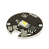
The upLED driver is designed for use with Thorlabs LEDs that feature M8 x 1 circular connectors, including our Mounted, Fiber-Coupled, Collimated, and Diffuse Backlight LEDs. This driver automatically adjusts the maximum current setting based on the information stored in the EEPROM chip, protecting the connected LED. PCB Mounted LEDs can also be driven with the upLED driver when used with the CAB-LEDD1 LED connection cable. Alternative LEDs can also be used, provided they have an M8 x 1 connector (see Pin Diagrams tab) and meet the specifications listed on the Specs tab. Note that the current limit will automatically be set to 1.2 A for these LEDs unless a lower value is specified in the software GUI.
Back Panel
The upLED driver features a USB 2.0 Type Mini-B interface, which connects the device with a computer running the upSERIES software. A USB-ABL-60 USB 2.0 type-A to mini-B cable is included with each device and this cable features an M2.5 locking screw to prevent accidental disconnections.
A status LED indicator is included on the back panel to easily identify the operation status of the device. When the LED indicator is green, the power supply is available, and an LED is connected and turned on; the LED blinks green when the connected LED is switched off. The indicator LED can also appear yellow or blink yellow, red, and green; these respectively signify that a power supply is available but an LED is not connected and the upLED is connected to an LED and PC but not to a power supply. Additional colors can also appear for special states; see the device manual for more details.
PC Control and Software
The upLED driver is controlled via a USB 2.0 connection and can be controlled through the upSERIES software. The software GUI displays the status of the LED and the current set point, as well as the measured voltage and current as reported by the upLED. When a Thorlabs LED is used, the current limit is automatically set using the information provided by the EEPROM. For more information on the upSERIES software features, please see the Software tab.
Note: The software includes an option that automatically repowers the LED after connecting a power supply, which allows the LEDs to power-up immediately without any safety notice. Always direct LEDs away from persons and reflecting surfaces prior to powering up the upLED.
Manual Control
The upLED can also control LEDs without the upSERIES software. If the "Repower LED after Power Cycle" setting is selected in the software, the LEDs can be started automatically after connection to a power supply, and the current applied depends on the software settings. If the current source is set to "Potentiometer", the LED lights up with the current set by the potentiometer value at the moment of power-up. However, when the current source is set to "User-defined", the LED lights up with the user-defined current set in the software and written to the upLED memory. See the Software tab for more details.
LEDs can also be manually controlled by using the POWER dial, i.e., a potentiometer, on the upLED; please see the Front & Back Panels tab for the location of this dial. The current is linearly increased by turning the power dial clockwise, and the maximum current is set by the current limit in the software or read out from the LED EEPROM. Note that if a Thorlabs LED is not used, the current limits is set to the maximum current of the upLED (1.2 A).
| Compatible Thorlabs LEDs | |||||
|---|---|---|---|---|---|
| Photo (Click for Link) |
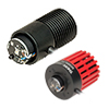 |
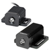 |
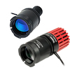 |
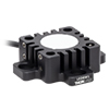 |
 |
| LED Description | Mounted | Fiber Coupled | Collimated | Diffuse Backlight | PCB Mounteda |
| Item # | UPLEDa |
|---|---|
| Constant Current LED Driver Specifications | |
| LED Current (Max) | 1.2 A |
| LED Forward Voltage (Max) | 8 V |
| LED Current Setting Resolution | 1 mA |
| LED Current Setting Accuracy | ±(1% + 10 mA) |
| Noise and Ripple (1 Hz to 10 MHz, RMS) | 0.5 mA |
| Measurement Specifications | |
| LED Current Measurement Resolution | 1 mA |
| LED Current Measurement Accuracy | ±(0.5% + 10 mA) |
| LED Voltage Measurement Resolution | 10 mV |
| LED Voltage Measurement Accuracy | ±(1% + 50 mV) |
| General Specifications | |
| Input Voltage | 12 V ± 5% |
| Digital Control Interface | Lockable Mini USB Connector |
| USB Protocol | USB 2.0 (USB CDC Class Device) |
| Manual Control Interface | Linear Power Potentiometer |
| Operating Temperature Range | 0 to 40 °C |
| Storage Temperature Range | -40 to 70 °C |
| Warm-Up Time for Rated Accuracy | 10 Minutes |
| Dimensions (W x H x D) | 93.2 mm x 27.0 mm x 52.5 mm (3.67" x 1.06" x 2.07") |
| Weight | 70 g |
| Power Supply Specifications | |
| DC Ouput | 12 V |
| Min Output Current | 1 A |
Click to Enlarge
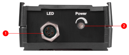
upLED Housing Front Panel Features
| upLED™ USB LED Driver Front Panel | |
|---|---|
| Callout | Description |
| 1 | M8 x 1 Circular LED Connector |
| 2 | Potentiometer for Current Adjustment |
Click to Enlarge
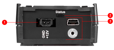
upLED Housing Rear Panel Features
| upLED USB LED Driver Rear Panel | |
|---|---|
| Callout | Description |
| 1 | Receptacle for Power Supply Cable or Adapter |
| 2 | Status LED |
| 3 | Lockable USB 2.0 Type Mini-B Connector with Threading for M2.5 Locking Screw |
Female M8 x 1 Circular LED Connector

| Pin | Description |
|---|---|
| 1 | LED Anode |
| 2 | LED Cathode |
| 3 | EEPROM GND |
| 4 | EEPROM IO |
2-Connection Power Supply Adapter Receptacle

| Pina | Description |
|---|---|
| 1 | GND |
| 2 | +12 V |
| Recommended System Requirements | |
|---|---|
| Operating System | Windows® 8.1 (64 Bit), Windows® 10 (64 Bit, Recommended) |
| Processor (CPU) | 1 GHz |
| Memory (RAM) | 512 MB |
| Hard Drive | 200 MB (Min) of Available Disk Space |
| Graphics Card Resolution |
1280 x 768 (Min) |
| Interface | Free USB 2.0 Port |
Software
Version 1.4
The upSERIES software includes a GUI for control of Thorlabs' upTEMP USB Temperature Data Logger and upLED LED Driver. To download, click the button below.
upSERIES® Software
The upSERIES Software is designed for straight forward use with the upTEMP™ Multichannel USB Temperature Logger and the constant current upLED™ LED Driver. The upSERIES Software can be used with several upTEMP and upLED models in parallel, allowing for complex setups.
Instrument drivers for LabVIEW®, CVI, C, C++, and C# are installed with the software for user-defined applications; refer to the manual for details.
Contents
upTEMP™ USB Temperature Data Logger
With the upSERIES software package, the temperature measurements detected by negative temperature coefficient (NTC) thermistors or resistive temperature detector (RTD) sensors can be monitored, saved, and evaluated using the intuitive, easy-to-use graphical interface. Ideal for complex systems, this software can be used to measure signals from multiple upTEMP modules, and each module can handle up to eight NTC thermistors or four RTD sensors. Data can be saved to the internal memory of the upTEMP device or to the PC.
The GUI features a configuration section, which allows the user to edit measurement parameters, including sensor type, temperature offset, and measurement delay. For real-time temperature monitoring, there is an option to display temperature measurements graphically in a time trace. Data analysis options, such as displaying single temperature values, are also included. Data saved to the PC will be saved as a .csv file with the following information: time and date; sensor type and number (according to list in the software); temperature scale; and calculated and displayed temperature values.
Click to Enlarge
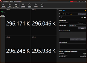
The upSERIES software automatically recognizes a connected upTEMP temperature logger. The connected upTEMP device is listed in the left panel and configuration options are on the right. The center panel shows the temperature readings for each connected temperature sensor.
Click to Enlarge
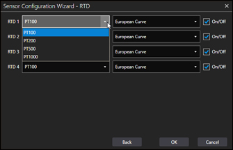
The category, which is based on the resistance at 0 °C (labelled as PTxxx), and the calibration curve can be set for connected RTD sensors.
Click to Enlarge
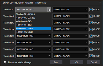
For connected NTC thermistors, the temperature coefficents and operating temperature ranges can be set. The Thermistor Model Manager also allows new NTC thermistors to be added, and they can be configured using the Steinhart-Hart equation or beta function.
Click to Enlarge
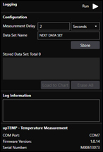
Measurement parameters can be configured in the right panel of the main GUI screen. Measurement delay, which is the update rate of the measured data on the screen, can be set, as well as the data set name. Also, options for saving the data can be set in this panel.
Click to Enlarge
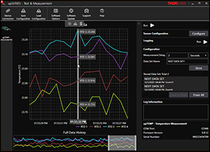
The live data can be displayed in the main GUI window. Also available are basic data analysis tools, including the capability to zoom into data sets and read the temperature for single data points. Time references for each data point can also be read out.
upLED™ Constant Current USB LED Driver
When using the upSERIES Software with the constant current upLED™ LED Driver, the forward current can be precisely set and saved for later applications. Additionally, software configurations allow the use of LEDs without Thorlabs EEPROMs, as well as automatic power-up options. This software can be used to drive multiple upLED modules and each upLED can drive a single LED.

Click to Enlarge
The upSERIES software automatically recognizes a connected upLED LED driver, provided an LED and power supply are already connected. The connected upLED is listed on the left panel, while the right panel shows configuration options. The LED status and current set point are shown in the center panel, as well as the measured voltage and current as reported by the upLED.
Click to Enlarge
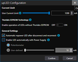
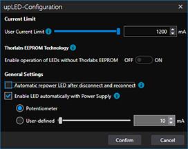
Additional information about each setting can be found by clicking on the blue icon next to the setting. The upLED can be set up for more hands-off operation; LEDs can automatically power on after connection to a power supply (see center image) or repower after being disconnected and reconnected. If an LED is disconnected during operation, the internal memory of the upLED will immediately resupply the next-connected LED with the last set of parameters.
Click to Enlarge
The configuration window allows the user to customize the upLED driver settings. Ideal for Thorlabs LEDs, the current limit is automatically set by the LED EEPROM. To use non-Thorlabs LEDs, toggle the switch under Thorlabs EEPROM Technology and set the current limit. The current source can be set as either the potentiometer or user-defined.
| Posted Comments: | |
user
(posted 2024-10-02 08:03:35.35) Hello, I can communicate with the devices using the upSeries software, but am having problems connecting using Labview. I am using Labview 2019 (64 bit) The TLUP Initialize.vi instrument, when called always reports error 0xBFFC0011 (Identification Query Failed), even if the "Id Query" toggle is set to "No". Also while using NI-MAX and sneding through VISA the command *IDN?\n the return is 1\n. GBoedecker
(posted 2024-10-04 09:55:00.0) Thank you for your feedback. I recommend to test with the provided Labview example. The UPLED is not a VISA device, therefore VISA commands cannot be used to communicate with it. For further assistance, please contact techsupport@thorlabs.com. Xindong Song
(posted 2024-05-18 19:20:22.73) I have 2 upLEDs in my system. However, when I open the software GUI or call the upLEDs through the API, it very often has only one upLED "connected", but not both. I wonder if there is any method for me to have both to stay "connected" in both the software GUI and through API. Thanks. hkarpenko
(posted 2024-05-21 05:40:26.0) Dear customer,
thank you for your feedback. I will contact you directly to discuss this issue with you. Jeff Secor
(posted 2024-05-08 13:10:45.757) Please provide communication documentation so that I can control this without the GUI on a mac. I can locate the device and endpoints on my mac but I dont know the command structure. Please make your products accessible to MacOS, else we can not use your products in our labs at Apple GBoedecker
(posted 2024-05-13 12:00:28.0) Thank you for your feedback! Unfortunately, currently we do not provide a GUI or SDK for MacOS. Many other of our products can be used on MacOS using serial commands. Jeff Secor
(posted 2024-03-20 10:24:58.823) Can you communicate with UPLED without the GUI? i.e. can i write a python script to control it? jjadvani
(posted 2024-03-21 04:29:44.0) Dear Jeff, Thank you for providing feedback. Of course, you can communicate with UPLED without using the GUI by running a Python script. Please visit the following link to see an example of how you can do that. https://github.com/Thorlabs/Current_And_Temperature_Controller_Examples/tree/main/Python/upLED%20and%20upTEMP%20Controllers Xindong Song
(posted 2023-10-02 13:51:56.297) I have a similar question as Toni Berger that I need to control the upLED in Matlab. However, the examples and functionality covered in the manual are not sufficient for me to proceed. Please let me know if there is any further information available. Thank you. GBoedecker
(posted 2023-10-04 09:52:32.0) Thank you for your feedback! We do not officially support Matlab, but you can use the provided .NET dll with "NET.addAssembly()". Hiroto Tanaka
(posted 2023-06-13 10:10:52.49) You are trying to control LED from a C# Console Application.
I want to switch the LED off next time I start the firmware.
I am exiting the program after setting Led_SwitchOnAtStartup(false), but the LED turns on the next time I power it on.
I tried setting Led_GetSwitchOnAtStartup(out state) after Led_SwitchOnAtStartup(false) and checking the value of state, but even if I set the value true/false for Led_SwitchOnAtStartup, the value of state is returned as true.
Is this a firmware bug? Or is my understanding wrong?
Also, if we can set the current value when switch the LED on, please let me know.
I know only how to set the current value after turning on the LED.
The version of firmware is Ver.1.3.5.
Best regards, Nazim Bharmal
(posted 2023-05-18 08:31:45.343) Our laboratory uses Linux as the infrastructure so we wish to connect UPLED units directly to this operating system, not via a Windows intermediary. Can you give me any information on Linux compatibility or other solutions that would suit computer control of the output of a fibre coupled LED? GBoedecker
(posted 2023-05-22 08:08:13.0) Dear Nazim, thank you very much for your feedback. The UPLED is not compatible with a LINUX system. Alternatively, you can use the DC2200 LED controller that can be operated with SCPI commands that work on Linux computers where NI VISA can be installed. chengyun hong
(posted 2023-04-26 12:44:53.917) hello
I am usiung the UPLED to control hte white light LED MWWHL4, however when I want to turn on the LED light with the software below message came out.
2023-04-26 12:41:40.0025 upSeries.upLED.ViewModels.MainContentViewModel Execute run command failed | Something went wrong with firmware! set output enabled failed. Error code is 0xBFFC0972
2023-04-26 12:42:48.1778 upSeries.upLED.ViewModels.MainContentViewModel Execute run command failed | Something went wrong with firmware! set output enabled failed. Error code is 0xBFFC0972
how I can turn on the light? dpossin
(posted 2023-04-26 08:06:13.0) Dear chengyun,
Thank you for your feedback. Probably this can be fixed via an firmware update. Therefore open the UpTEMP software panel and click on "Software Update". On the following panel you can update the firmware by loading in the firmware files you can download here: https://www.thorlabs.com/software_pages/ViewSoftwarePage.cfm?Code=upSERIES. Start the firmware update afterwards.
Please note that the device needs to stay connected to your computer via usb during that process.
I am reaching out to you in order to provide further support. Toni Berger
(posted 2022-10-13 09:10:35.037) Hi, is there some way of integrating the UPLed driver in a python script? So far, I've tried using cffi to embed the header and library files of the C++ driver in my Script, however, I receive Verification and Compile Errors (Probably due to some communication errors with Visual Studio Code). So I wondered, if there is another way (as I've seen another user already tried something similar).
Any Help would be much appreciated. wskopalik
(posted 2022-10-14 10:25:27.0) Thank you for your feedback!
You can use the ctypes library in Python to control the upLED. With this library you can access the DLL files which are provided in the installation package.
I will contact you directly to provide further information. user
(posted 2022-08-30 12:19:10.45) Is there any documentation or support for Python using pyvisa, ctypes dll, or pyserial. The device doesn't return any meaningful information when querying with standard visa commands, e.g. "*IDN?" I would expect to see something with the Thorlabs ID 0x1313 in the reply message. Would it be possible to see an example connecting to the device and setting a current value? mdiekmann
(posted 2022-08-31 09:42:46.0) Thank you for contacting us. We will reach out to you directly to send you some examples and supporting information. Majid Ansari-Asl
(posted 2022-04-14 10:13:23.99) Hi, I am trying to run C++ example solution (upSERIES_CSample.sln) using Visual Studio 2019 but this error happens,
fatal error C1083: Cannot open include file: 'vpptype.h'
Do you know what is the problem? Do I need to install any driver beforehand (I've already installed upSERIES software)? Thanks GBoedecker
(posted 2022-04-25 09:39:55.0) Thank you for reaching out to us with this inquiry. We have contacted you directly to troubleshoot the software-related issue. En-Chuan Huang
(posted 2022-02-14 12:01:56.4) The website said that for other drivers, refer to the manual for details. However, I could not find anything, specifically for C++, in the software manual. Could you point it to me?
Secondly, is there any support for python? GBoedecker
(posted 2022-02-16 08:16:55.0) Dear En-Chuan,
thank you for your inquiry. The software manual explains the GUI. The information about the drivers can be found in the device manual, chapter 4 "Write Your Own Application". I will contact you directly to discuss your question about python. user
(posted 2021-08-08 03:04:19.877) Is it possible to use upLED with LED255J UV diode I already had in my lab? dpossin
(posted 2021-08-09 07:22:07.0) Dear Pawel,
Thank you for your feedback. The upLED can be used with any LED which do not exceed the maximum current it can provide. Therefore the LED255J can be driven by the upLED using the connection cable CAB-LEDD1. I am reaching out to you in order to provide further information on that. |

| Key Specsa,b | |
|---|---|
| Constant Current LED Driver Specifications | |
| LED Current (Max) | 1.2 A |
| LED Forward Voltage (Max) | 8 V |
| LED Current Setting Resolution | 1 mA |
| LED Current Setting Accuracy | ±(1% + 10 mA) |
| Noise and Ripple (1 Hz to 10 MHz, RMS) | 0.5 mA |
| Measurement Specifications | |
| LED Current Measurement Resolution | 1 mA |
| LED Current Measurement Accuracy | ±(0.5% + 10 mA) |
| LED Voltage Measurement Resolution | 10 mV |
| LED Voltage Measurement Accuracy | ±(1% + 50 mV) |
- USB-Controlled Constant Current LED Driver for Thorlabs LEDs with an M8 x 1 Connector
- Current Adjustment via Integrated Potentiometer or with Included upSERIES® Software
- USB-ABL-60 USB 2.0 Type-A to Mini-B Cable with M2.5 Locking Screw Included
- Requires a 12 V, 1 A Power Supply
- Recommended Item #: DS12 (Sold Below)
Thorlabs' upLED™ LED Driver is a compact USB-controlled driver that can be controlled manually with a linear potentiometer (see Front & Back Panels tab) or through the included upSERIES software. Intended for use with Thorlabs LEDs that feature an M8 x 1 circular connector, this driver it is able to read current information stored in the EEPROM.
Each upLED driver can control a single LED. When using more than one driver to control multiple LEDs, the upLED devices can be stacked using the connection channels on the corners of the housing. This creates a stable assembly that retains the compact footprint of a single device (86.7 mm x 52.5 mm). For secure mounting to an optical table or breadboard, we recommend using the upBASE base plate sold below.
Power Supply (Not Included, Sold Below)
A 12 V, 1 A power supply is required to operate the upLED driver. We recommend the DS12 power supply (sold below). Each upLED driver ships with an adapter cable for use with the DS12 power supply. Alternatively, a user-assembled power supply may be used. Each driver ships with a power supply adapter, into which the user can insert two 0.5 mm2 wires that provide at least 1 A at 12 V.

Click to Enlarge
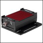
An upLED module mounted onto the upBASE base plate.
- Four M3 Countersunk Holes for Mounting to an upSERIES® Device
- Mounts to an Optical Table or Breadboard via a Slot for 1/4" (M6) Cap Screws
- Four M3 x 0.5 Countersunk Screws (2 mm Hex) are Included
The upBASE Base Plate securely mounts an upSERIES module to an optical table or breadboard. A slotted hole for 1/4" and M6 cap screws provides compatibility with both imperial and metric hole patterns. The bottom of the upSERIES module is connected to the base plate using the four included M3 x 0.5 countersunk screws. Fabricated from black anodized aluminum, the bottom of this base has three contact pads for stable mounting; one contact pad is located around the slotted hole and the other two are around the countersunk holes at the opposite end of the plate.
The upBASE base plate increases the footprint of an upSERIES device to 86.7 mm x 70.0 mm (3.41" x 2.76").

- 12 VDC Power Output
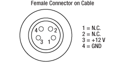
- 4.1 ft (123 cm) Cable with M8, 4-Pin Female Connector
The DS12 is a 12 VDC power supply with a 1.23 m long cable and an M8, 4-pin female connector, and operates at an input voltage of 100 - 240 VAC. It is compatible with any male M8, 4-pin device that accepts a 12 VDC output. The DS12 ships with a region-specific AC cable.
 Products Home


 Zoom
Zoom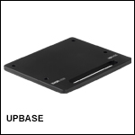
 upLED™ Constant Current LED Driver