 Products Home / Drivers & Mounts / Optoelectronics Mounts / TO Can Laser Diode Mounts / Collimation Packages / Laser Diode Collimation and Focusing Tubes
Laser Diode Collimation and Focusing Tubes
- Collimation and Focusing Tubes for Laser Diodes
- Aspheric Optics Premounted in Ø15 mm Aluminum Tubes
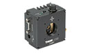
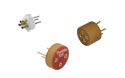
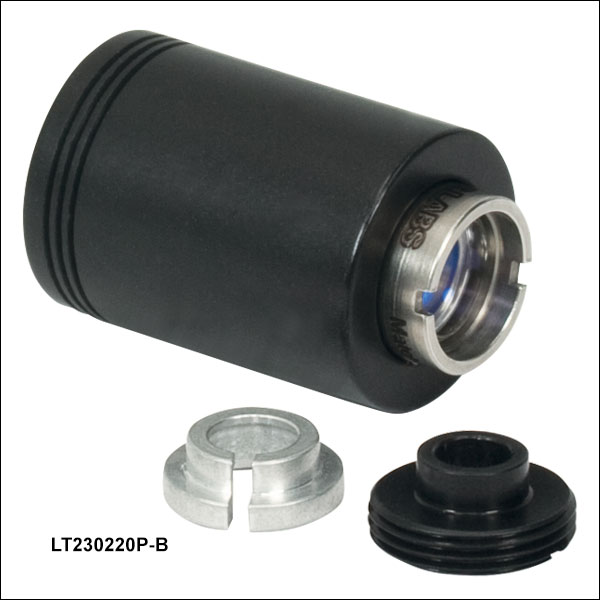
LT230220P-B
Focusing Tube with Optic
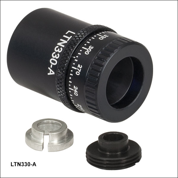
LT110P-B
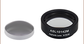
Collimation Tube with Optic
(Laser Diode Sold Separately)
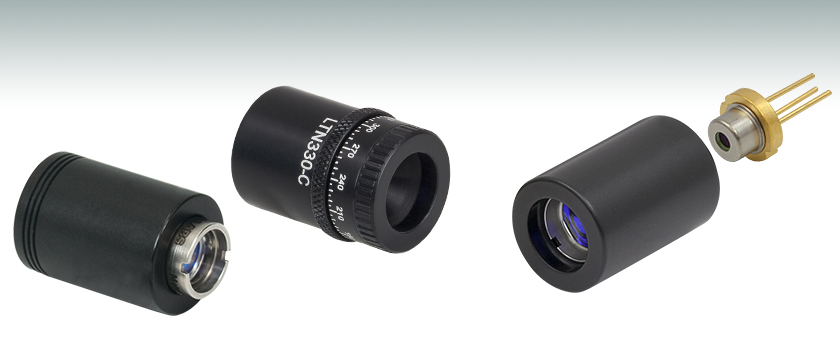
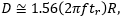
LTN330-C
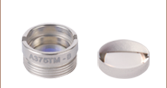
Adjustable Laser Diode Collimation Tube with Optic


Please Wait
Features
- Collimation or Focusing Tubes Designed for Use with TO Can Laser Diodes
- Compatible with Thorlabs' ESD Protection and Strain Relief Cables
Thorlabs offers passive laser diode mounts with premounted aspheric optics for collimation or focusing applications. Each of these mounts is compatible with our strain relief and ESD protection cables, also offered below. These mounts are compatible with low-power Ø5.6 mm or Ø9 mm laser diode packages and do not offer active cooling. They can be adapted to standard Ø1" mounts such KM100 Kinematic Mount using the AD15NT Adapter. They can also be mounted in SM1-threaded lens tubes and optomechanics using the AD15F or AD15F2 Adapters.
| Laser Diode Accessory Selection Guide | |||||
|---|---|---|---|---|---|
| Temperature Controlled Mounts |
Passive Mounts | Other Passive Mounts with Collimation Package |
Strain Relief Cables | Diode Sockets | Controllers |
 |
 |
 |
 |
 |
 |
| Adjustable Laser Diode Collimation Tubes and Optics | ||||||
|---|---|---|---|---|---|---|
| Item # | AR Coating Range |
Effective Focal Length |
Numerical Aperture |
Aspheric Optic | Lens Info | Minimum Package Length |
| LTN330-A | 350 - 700 nm | 3.1 mm | 0.68 | 354330-A | 0.87" (22 mm) | |
| LTN330-B | 600 - 1050 nm | 3.1 mm | 0.68 | 354330-B | 0.87" (22 mm) | |
| LTN330-C | 1050 - 1700 nm | 3.1 mm | 0.68 | 354330-C | 0.87" (22 mm) | |
| Laser Diode Collimation Tubes and Optics (for 650 - 1050 nm) | ||||||
|---|---|---|---|---|---|---|
| Item # | AR Coating Range |
Effective Focal Length |
Numerical Aperture |
Aspheric Optic | Lens Info | Package Length |
| LT230P-B | 650 - 1050 nm | 4.51 mm | 0.55 | A230TM-B | 0.75" (19 mm) | |
| LT110P-B | 6.24 mm | 0.40 | A110TM-B | 0.85" (22 mm) | ||
| LT240P-B | 8.00 mm | 0.50 | A240TM-B | 0.95" (24 mm) | ||
| LT220P-B | 11.0 mm | 0.26 | A220TM-B | 1.00" (25 mm) | ||
| Adjustable Laser Diode Focusing Tubes and Optics (for 600 - 1050 nm) | ||||||
|---|---|---|---|---|---|---|
| Item # | AR Coating Range |
Effective Focal Length |
Numerical Aperture |
Aspheric Optic Pair | Component Lens Info |
Package Lengtha |
| LT230220P-B | 600 - 1050 nm | 4.51 mm | Laser Side: 0.55 Focus Side: 0.25 |
C230220P-B | 0.8" (20.3 mm) | |
| LT230260P-B | Laser Side: 0.55 Focus Side: 0.16 |
C230260P-B | ||||

Insights into Beam Characterization
Scroll down to read about:
- Beam Size Measurement Using a Chopper Wheel
Click here for more insights into lab practices and equipment.
Beam Size Measurement Using a Chopper Wheel
Click to Enlarge
Figure 2: The blade traces an arc length of Rθ through the center of the beam and has an angular rotation rate of  f. The chopper wheel shown is MC1F2.
Click to Enlarge
Figure 1: An approximate measurement of beam size can be found using the illustrated setup. As the blade of the chopper wheel passes through the beam, an S-curve is traced out on the oscilloscope.
Click to Enlarge
Figure 4: The diameter of a Gaussian beam is often given in terms of the 1/e2 full width.

Click to Enlarge
Figure 3: Rise time (tr ) of the intensity signal is typically measured between the 10% and 90% points on the curve. The rise time depends on the wheel's rotation rate and the beam diameter.
Camera and scanning-slit beam profilers are tools for characterizing beam size and shape, but these instruments cannot provide an accurate measurement if the beam size is too small or the wavelength is outside of the operating range.
A chopper wheel, photodetector, and oscilloscope can provide an approximate measurement of the beam size (Figure 1). As the rotating chopper wheel's blade passes through the beam, an S-shaped trace is displayed on the oscilloscope.
When the blade sweeps through the angle θ , the rise or fall time of the S-curve is proportional to the size of the beam along the direction of the blade's travel (Figure 2). A point on the blade located a distance R from the center of the wheel sweeps through an arc length (Rθ ) that is approximately equal to the size of the beam along this direction.
To make this beam size measurement, the combined response of the detector and oscilloscope should be much faster than the signal's rate of change.
Example: S-Curve with Rising Edge
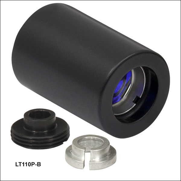
The angle ftr )ftr )
includes a factor of 1.56, which accounts for the portion of the beam measured between the 10% and 90% intensity points being smaller than the 1/e2 beam diameter.
Date of Last Edit: June 22, 2021
Content improved by our readers!
| Posted Comments: | |
Li-Bang Wang
(posted 2021-10-08 01:09:15.343) It is very inconvenient that I cannot buy the tube with A coating lens. The lens has to be bought separately and the B-coating lens in the tube is wasted. YLohia
(posted 2021-10-11 02:19:35.0) Hello, thank you for your feedback. We're sorry to hear about the inconvenience caused by the lack of coating options. We will consider offering various AR-coated versions of these collimation tubes in the future. user
(posted 2020-08-25 10:07:45.0) I have you collimating tube LTN330-A. Will it be compatibile with USHIO laser diode: HL65213HDhttps://www.ushio.eu/659nm-biomedical-laser-diode/ ? YLohia
(posted 2020-08-25 10:19:03.0) Hello, thank you for contacting Thorlabs. The HL65213HD is a 9mm TO-can laser diode so, yes, the LTN330-A will be compatible with this item. user
(posted 2019-08-07 07:30:57.453) Hi, is it possible to mount the Focusing Tube with Optic (LT230220P-B) on the Laser Diode Mount with Integrated TEC and Controller (LDM9T/M)?
thank you YLohia
(posted 2019-08-07 04:01:20.0) Hello, thank you for contacting Thorlabs. We do not recommend using the LT230220P-B with the LDM9T (as well as our current LDM series of mounts) as it defeats the purpose of using the special temperature control features of the mount. The C230220P-B collimation lens can be used with the S1TM09 adapter with the LDM9T. user
(posted 2019-04-19 02:42:44.117) It would be great if you put LT110P-C in the category. otherwise I don't know how to order if I want different coating on the lens. YLohia
(posted 2019-04-19 09:56:55.0) Hello, we do have the ability to offer custom coatings on our lenses. For inquiries on custom items, please email techsupport@thorlabs.com for a quote. thutches
(posted 2017-11-29 14:06:54.447) Couldn't find details about the lens that is prepackaged in the LTn330-A unit. Can you (anyone) help me with a Zemax file or other information? Thanks nbayconich
(posted 2017-12-01 04:38:31.0) Thank you for contacting Thorlabs. The lens used in the LTN330-A is the 354330-A Geltech asphere. The Zemax files for these collimation tubes can be found under the Specs tab located on the Laser Diode Collimation and Focusing Tubes page. ytoh
(posted 2017-07-22 22:21:28.85) On line 4, the principal plane to mounting surface is listed as 8.7mm. However, the math does not add up. I think this is incorrect and 8.7mm is the correct distance for the LT110P-B? tcampbell
(posted 2017-12-29 11:20:53.0) Hello, thank you for contacting Thorlabs. We have updated this value for several of our laser diode collimation tubes. The correct distance can now be found on the mechanical drawings. mitch
(posted 2016-08-28 07:36:18.443) Hi I have purchased several LTN330-B but I am wondering if they will work with a TO-46 package laser diode? Will the TO-46 fit into the adapter ring? tfrisch
(posted 2016-09-06 03:20:43.0) Hello, thank you for contacting Thorlabs. I have reached out to you directly, but the TO-46 package will not fit. user
(posted 2015-08-27 05:46:50.68) Dear Sir or Madam,
I tried to collimate a L785P090 diode using the
LN330-B. What I see is that the beam gets like
cut on one side and shows strong diffraction at larger distances. My guess was that is most likely a sign that the output facet of the diode is not centered on the lens. Is there way to align the diode somehow ?
Thanks and Regards,
Christoph besembeson
(posted 2015-09-25 05:40:38.0) Response from Bweh at Thorlabs USA: Please contact me at techsupport@thorlabs.com for us to discuss this. wenxingpath
(posted 2015-08-27 15:44:50.033) To Whom It May Concern,
I have a question with your product “LTN330-B Adjustable Laser Diode Collimation Tubes and Optics”.
I would like to buy LTN330-B to collimate your Laser Diode L785P090 to get a output collimated beam with 2mm diameter. Is it possible?
And if it is ok, may I use this LTN330-B to collimate Laser Diode with 850nm or 900nm output wavelength to get a collimated beam with 2mm or 3mm diameter?
Thanks and looking forward to your response.
Best regards
Leo besembeson
(posted 2015-09-28 05:55:16.0) Response from Bweh at Thorlabs USA: That will not be suitable. The lens that comes with the LTN330-B has a focal length too short. It will be about 0.6mm output beam diameter. The wavelengths will be okay (considering the -B AR coating) but you will need an aspheric lens with a working distance of about 8mm. We have these at the following link: http://www.thorlabs.us/newgrouppage9.cfm?objectgroup_id=3811&pn=354330-B#4438 bonin
(posted 2015-02-25 00:12:29.33) What size laser beam diameter does the LTN330-A collimation package provide when the output laser beam is collimated? Also, how circularized is the output beam? Thanks jlow
(posted 2015-02-25 03:08:39.0) Response from Jeremy at Thorlabs: The output beam diameter is going to be dependent on the divergence of your laser diode. The effective focal length of the aspheric lens used is about 3.1mm so that can be used to estimate the collimated output beam diameter. The aspheric lens does not circularized the beam. lovecrazydog
(posted 2014-06-17 11:32:18.383) How much current/heat can be allowed for these products? jlow
(posted 2014-07-29 03:55:37.0) Response from Jeremy at Thorlabs: There's no temperature regulation for these collimation tube so it should be used for low-power LD only. The max. current would depend on the individual laser diode you are using. hagdes
(posted 2014-02-04 13:07:58.087) Hello,
I would like tu buy some laser diode collimator for a diode laser centered at 975 nm and 500 mW as maximun power. I heve seen in the website that you have four products that could meet the requeriments LT110P-B, LT220P-B, LT230P-B and LT240P-B . I would be very glad if you can suggest me any product. The laser diode is from axel photonics. Please follow this link for datasheet, http://www.axcelphotonics.com/images_clients/pdf/980nm_Multi_Mode_Specs_50um_.pdf
Thank you jlow
(posted 2014-02-04 01:29:25.0) Response from Jeremy at Thorlabs: I will contact you to get more information on your application such as beam diameter requirement, can package of your laser diode, and the way you are mounting/driving it. user
(posted 2011-08-08 05:53:43.0) I dont understand why you dont add LT230P-A and LT230P-C to your product lists. Although the tube and lens can be ordered separately by contacting your representatives, it will be easier to shop on line and pay by credit card if the one with different coatings has its own part number. jjurado
(posted 2011-07-12 10:39:00.0) Response from Javier at Thorlabs to metz: Thank you very much for contacting us. We can certainly offer the LT230P-B collimation tube without the optic. I will contact you directly with a quotation. metz
(posted 2011-07-12 16:19:52.0) Hi:
I would like to buy only the collimation tube, which is included in the collimation package "LT230P-B". Is this possible?
Best regards,
Jonas Metz jjurado
(posted 2011-02-16 11:37:00.0) Response from Javier at Thorlabs to last poster: Thank you very much for pointing this error out. We will rectify the information on the drawing shortly. user
(posted 2011-02-15 21:19:30.0) for information theres a mistake (that almost got me !) on the AutoCAD PDF file of the collimation tube LT240 (8mm FL):
the internal thread is M12x0.5, not M9 as indicated. user
(posted 2010-02-05 02:25:35.0) it will be great if you can have separate part number for the tubes, and does not include the lens so people can order online easily info
(posted 2009-08-08 04:49:37.0) Dear Sir / Madam, I saw your website and impressed by Laser Diode Collimators products. We try to manufacture prototype laser rangefinder with diode laser that specified below. For this we need an optics unit to reduce beam divergence to 0.5 mrad. We search some companies and find your system can be useful for ours. If you can support us we hare very glad to hear about your suggestion. We have a diode laser that specification as below: 1. Partnumber: 905D3S3J08R 2. Company: Laser Components 3. Wavelength: 905 nm 4. Peakpower: 210 W 5. Beam Spread (50% peak intensity) Parallel: 11 degrees Perpendicular: 25 degrees 6. Emitting Area: 200 um* 250 um 7. Package: R= 9 mm CD 8. Laser windows Thickness: 0.25 mm 9. Datasheet: http://www.lasercomponents.com/uk/fileadmin/user_upload/home/Datasheets/lcc/905d3j09.pdf 10. Quantity: 5 pcs I appreciate it if you could give me an estimate of the cost and some information about delivery time, Shipping. Thanks & Best regards klee
(posted 2009-06-26 14:40:32.0) A response from Ken at Thorlabs to futia: We can offer special collimation tubes with C-coated (1050 - 1600 nm) lenses. Please send an email to techsupport@thorlabs.com, indicating which of the 4 tubes you need, and we will send you a quote. futia
(posted 2009-06-26 14:31:00.0) It would be useful if ThorLabs sold Collimation Tubes with optics coated for 1050 to 1500nm as well. Greg
(posted 2009-04-10 08:18:18.0) A response from Greg at Thorlabs to aidi: The LT230P-B is compatible with the SR9A-DB9, but neither is compatible with the ITC502. In order to temperature controller your laser, you need a TEC element. If you are looking for a collimated laser that you can also temperature control, I suggest looking at our Fiber Pigtailed Lasers and using one with our TCLDM9 TEC mount. You will then need a laser diode driver and TEC controller. If you have further questions, please let me know via e-mail. aidi
(posted 2009-04-09 21:12:24.0) Is this SR9A-DB9 can work together with LT230P-B collimation tube and ITC502 Temperature controller? Thank you Laurie
(posted 2009-02-25 08:07:33.0) Response from Laurie at Thorlabs to aidi: Thank you for considering Thorlabs as the solution to your optical and photonic needs. For collimating the output of a laser diode, you will want to consider the following points when selecting the optimal focal length: (1) Be sure to select a lens with an NA equal to or larger than that of your diode. This diode has a maximum NA of .423. (2) From the lenses with an appropriate NA, select the correct focal length for your application. A longer focal length will equate to a larger diameter beam with a smaller divergence angle. A shorter focal length will have a smaller output beam diameter, but it will have a larger angle of divergence. Both the LT230P-B and the LT240P-B has the appropriate NA and AR coating for your wavelength. aidi
(posted 2009-02-19 03:43:53.0) I have L780P010 laser diode. Which collimating item is suitable for me so that the output laser can transmit and focus properly? And what others accesories needed? Thank you. Tyler
(posted 2009-01-08 16:32:01.0) A response from Tyler at Thorlabs to melsscal: One more thing, the SR9A is compatible with the TLD001. Tyler
(posted 2009-01-08 16:30:10.0) The LPS-635-FC can be used with the SR9A. However, we generally recommend a laser diode mount with temperature control (TCLDM9) when driving a pigtailed laser diode. Fluctuations in temperature can affect the stability of the laser output. If the laser diode is being operated near the maximum current limit, temperature fluctuations could lead to the maximum current being exceed, which would cause the LD to burn out. Thank you for your question and if we can be of any further service please feel free to ask. melsscal
(posted 2009-01-08 07:38:06.0) Dear Sir,Can I connect the LPS-635-FC to SR9A ?
Regards A.K.Bose
MELSS,
KOLKATA
melsscal@melss.com melsscal
(posted 2009-01-08 07:35:22.0) can we USE the SR9A-DB9 TO connect the LPS-635-FC to the TLD001 ?
Regards
A.K.Bose
MELSS
KOLKATA/INDIA
melsscal@melss.com ghegenbart
(posted 2008-11-28 08:46:07.0) Response from Gerald (Tech Support Thorlabs GmbH Germany) to M. Zimmermann:
On the beam output side there is a rubber O-ring that provides friction fit of the mounted lens. The diameter of the groove the O-ring sits in is about 14.0 mm in case of the LT240P and about 12.3 mm for the other types. So it is not possible to have SM05 threads at that end. However, on the laser diode side the internal diameter of the opening is about 9.7 mm. So indeed having SM05 threads there would be feasible. Those threads would give mounting options in particular for very small setups that the current product in combination with the AD15F does not provide. So thank you very much for this very valuable feedback. I will suggest to modify the product. m.zimmmermann
(posted 2008-11-28 05:19:54.0) Is it possible to make a thread outside of one or both sides of the LT110P-B (or other modules) so that the customer can adapt this item to the lens tube system SM05? This would be very helpful. Tyler
(posted 2008-03-27 08:14:18.0) Response from Tyler at Thorlabs to rachel: The A110TM-C can be installed in the LT110P-B. However, since the LT110P-B includes a collimation lens, it would be better to contact our technical support department and get a custom quote for a collimation tube with the A110TM-C as the collimation optic. One other note, the ML725B8F has a D-type pin configuration, so the proper laser diode mount would be the SR9D-DB9, not the SR9A-DB9. Thank you for your interest in our products. rachel
(posted 2008-03-24 21:57:09.0) Dear sir,
I would like to purchase ML725B8F 1310nm laser diode, LT110P-B and SR9A-DB9. But I confirm if aspheric optic can be installed A110TM-C(AR Coated 1050-1550nm) in LT110P-B. Thanks! I am looking forward to hearing from you soon.
Rachel Chen
Hortek Crystal Co., Ltd. |

 Zoom
Zoom
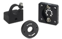
Click to Enlarge
Figure G1.1 Adjustable Laser Diode Collimation Tubes are Compatible with SR9 Strain Relief and ESD Protection Cables
- Adjustable Lens Mount with Collimating Optic for our LD Sockets with Strain Relief Cables (Sold Below)
- 13/32"-40 Threaded Retaining Ring Secures Ø5.6 mm or Ø9 mm Laser Diode
- Aspheric Collimation Optic with One of Three Broadband AR Coatings:
- A Coating: 350 - 700 nm
- B Coating: 600 - 1050 nm
- C Coating: 1050 - 1700 nm
- Rotating Cap with Locking Ring Provides 2.5 mm (0.1") of Lens Travel for an Adjustable Focus
- Includes Main Tube with Mounted Optic, Retaining Ring, and Adapter Kit for Ø5.6 mm Diode Packages
- Ø15 mm (Ø0.58") Tube Can be Mounted Using a Ø1" AD15NT Adapter or SM1-Threaded AD15F or AD15F2 Adapters
- Laser Diode Retaining Ring Compatible with SPW301 and SPW801 Spanner Wrenches
Thorlabs' Adjustable Laser Diode Collimation Tubes are shipped with an aspheric lens (collimation optic) premounted. The position of this lens can be adjusted by up to 2.5 mm (0.1") by rotating the cap on the end of the tube. The position of the lens can then be locked using the external locking ring. Rotation of the cap by 5° corresponds to a linear displacement of the lens by 5.5 µm, and an engraved scale on the actuating cap allows for accurate lens positioning. The lens translates inside the tube without rotation for enhanced pointing stability. The large travel range of the optic ensures that these collimation tubes can be used to collimate any of Thorlabs' laser diodes that emit within their AR coating range. However, the lens in these collimation tubes is not meant to be replaced.
The SPW301 spanner wrench can be used to install any of our Ø5.6 mm or Ø9 mm laser diodes in the collimation tube. A Ø9 mm laser diode can be directly installed into the tube with the included retaining ring, while a Ø5.6 mm laser diode can be installed with the use of the included adapter kit.
Laser Diode Temperature Warning
Please note that these collimation tubes do not have any temperature regulation or temperature measurement capability, so we do not recommend using them with higher power laser diodes without additional thermal regulation. Running a laser diode at a high operating temperature can significantly shorten its lifetime.
Mounting Options
Thorlabs' Adjustable Laser Diode Collimation Tubes can be secured in a KM100 Kinematic Mount using the AD15NT adapter. Alternatively, they can be mounted in an SM1-threaded mount using our AD15F adapter, as illustrated in Video 1.1. However, the outer diameter of the external locking ring on these collimation tubes will not fit in these adapters. As such, the tubes can only be placed into the adapter in one direction, and they will not pass all the way through the adapter. Therefore, the laser diode socket should be passed through the adapter before connection to the diode in the collimation tube. Alternatively, the locking ring can be removed by first removing the tube's end cap. As an alternative mounting option, these collimation tubes can be secured in a KM100V kinematic V-mount.
")
 Zoom
Zoom
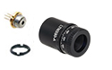
Click to Enlarge
Figure G2.1 Laser Diode Collimation Tubes are Compatible with SR9 Strain Relief and ESD Protection Cables
- Lens Mount with Collimating Optic for our Laser Diode Sockets with Strain Relief Cables (Sold Below)
- 13/32"-40 Threaded Retaining Ring Secures Ø5.6 mm or Ø9 mm Laser Diode
- Aspheric Collimation Optic that is AR Coated for 650 - 1050 nm
- Includes Main Tube, Optic, Retaining Ring, Rubber O-Ring, and Adapter for Ø5.6 mm Diode Packages
- Ø15 mm (Ø0.58") Tube Can be Mounted Using a Ø1" AD15NT Adapter or SM1-Threaded AD15F or AD15F2 Adapters
- Laser Diode Retaining Ring Compatible with SPW301 and SPW801 Spanner Wrenches
Other Wavelength Ranges and Collimation Optics
The Laser Diode Collimation Tube is shipped with the aspheric lens (collimation optic) premounted. However, a different aspheric lens can be substituted for better performance at different wavelengths. Any of our M9 x 0.5 threaded mounted aspheric lenses are compatible with the LT110P-B, LT220P-B, and LT230P-B collimation tubes, while any of our M12 x 0.5-threaded mounted aspheric lenses are compatible with the LT240P-B collimation tube. The SPW301 or SPW302 spanner wrenches, respectively, can be used to remove and install these two sizes of aspheric lenses. Please contact Tech Support if you would like to purchase the collimation tube without the aspheric lens, or with a different lens.
Laser Diode Temperature Warning
Please note that these collimation tubes do not have any temperature regulation or temperature measurement capability, so we do not recommend using them with higher power laser diodes without additional thermal regulation. Running a laser diode at a high operating temperature can significantly shorten its lifetime.
| Specifications | ||||||
|---|---|---|---|---|---|---|
| Item # | AR Coating Range |
Effective Focal Length |
Numerical Aperture |
Aspheric Optic | Lens Info | Package Length |
| LT230P-B | 650 - 1050 nm | 4.51 mm | 0.55 | A230TM-B | 0.75" (19 mm) | |
| LT110P-B | 6.24 mm | 0.40 | A110TM-B | 0.85" (22 mm) | ||
| LT240P-B | 8.00 mm | 0.50 | A240TM-B | 0.95" (24 mm) | ||
| LT220P-B | 11.0 mm | 0.26 | A220TM-B | 1.00" (25 mm) | ||
")
 Zoom
Zoom
Click to Enlarge
Figure G3.1 Laser Diode Collimation Tubes are Compatible with SR9 Strain Relief and ESD Protection Cables
- Lens Mount with Adjustable Focus for our Laser Diode Sockets with Strain Relief Cables (Sold Below)
- 13/32"-40 Threaded Retaining Ring Secures Ø5.6 mm or Ø9 mm Laser Diode
- Aspheric Focusing Optic Pair that is AR Coated for 600 - 1050 nm
- Includes Main Tube, Optic, Retaining Ring, Rubber O-Ring, and Adapter Kit for Ø5.6 mm Diode Packages
- Ø15 mm (Ø0.58") Tube Can be Mounted Using a Ø1" AD15NT Adapter or SM1-Threaded AD15F or AD15F2 Adapters
- Laser Diode Retaining Ring and Aspheric Lens Pair Compatible with SPW301 and SPW801 Spanner Wrenches
These laser diode focusing packages are similar to our laser diode collimation packages sold above but include an aspheric lens pair for focusing of the laser diode output. The focus can be adjusted by threading the mounted lens pair in or out. These packages are compatible with our SR9 laser diode sockets, available below.
Laser Diode Temperature Warning
Please note that these collimation tubes do not have any temperature regulation or temperature measurement capability, so we do not recommend using them with higher power laser diodes without additional thermal regulation. Running a laser diode at a high operating temperature can significantly shorten its lifetime.
| Specifications | ||||||
|---|---|---|---|---|---|---|
| Item # | AR Coating Range |
Effective Focal Length |
Numerical Aperture |
Aspheric Optic Pair | Component Lens Info |
Package Lengtha |
| LT230220P-B | 600 - 1050 nm | 4.51 mm | Laser Side: 0.55 Focus Side: 0.25 |
C230220P-B | 0.8" (20.3 mm) | |
| LT230260P-B | Laser Side: 0.55 Focus Side: 0.16 |
C230260P-B | ||||

 Zoom
Zoom| Item # Prefixa |
Supported Pin Style |
Component Socket |
Max LD Forward Voltage |
|---|---|---|---|
| SR9A | A and E | S8060 | 3.3 V |
| SR9B | B and H | S8060 | |
| SR9C | C and H | S8060 | |
| SR9D | D | S8060-4 | |
| SR9F | F and G | S8060-4 | |
| SR9HA | A and E | S8060 | 7.5 V |
| SR9HB | B and H | S8060 | |
| SR9HF | F and G | S8060-4 |
| Diode Compatibility with Strain Relief Cables | ||
|---|---|---|
| Laser Diodes | Ø3.8 mm | x |
| Ø5.6 mm | o | |
| Ø9.0 mm | ||
| TO Can Packages | TO-5 | x |
| TO-18 | o | |
| TO-46 | o | |
 Fully Compatible
o Not a Perfect Fit, but Functional
x Not Compatible
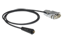
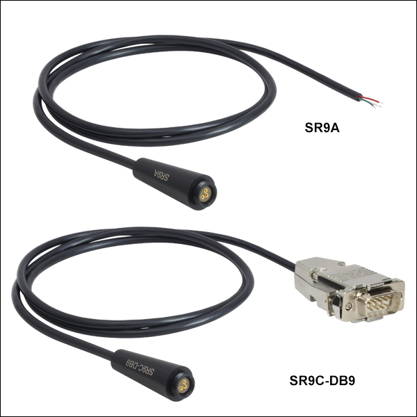
- Designed for Use with Either Ø5.6 mm or Ø9 mm Laser Diodes
- Includes Laser Socket and 3 Feet (0.91 m) of Shielded Cable
- External 13/32"-40 Threads for Compatibility with Select Laser Diode Accessories:
- Includes Clamping and Reverse Protection Diodes to Suppress ESD
- Available with DB9 Connector for Mating Directly with LDC200C Series Laser Controllers
These strain relief and ESD protection products offer a convenient means of connecting a Ø5.6 mm or Ø9 mm laser diode to many of Thorlabs' laser diode controllers. Each model comes with a laser socket mounted to a small-printed circuit board (PCB). The PCB contains a Schottky diode to clamp any reverse voltages that might appear across the laser diode, as well as a Zener diode to shunt any excessive voltages or ESD away from the diode.
Each model corresponds to one or more of the standard Pin Styles for laser diodes (see Figure 222A) and is compatible with our Laser Diode Collimation and Focusing Tubes, Ø1/2" Post Mounts, and Cage Plate Mounts. SR9 models are designed for laser diodes with forward voltages up to 3.3 V, while SR9H models are designed for laser diodes with forward voltages up to 7.5 V. Each strain relief is available with or without a DB9 connector. Models with item #'s that end in -DB9 are pin compatible with many of our Laser Diode Controllers (see the strain relief cable and controller pin diagrams to determine compatibility).
Note: These cables are not designed to provide any temperature regulation. More information on temperature regulating a laser diode is provided in the Laser Diode Tutorial.
Figure 222A Supported Pin Codes