Single Photon Counting Device
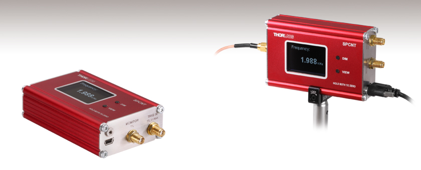
- Count Pulses from Single Photon Detectors
- Monitor Counts with Built in Display or PC
- Input Signals up to 100 MHz
- Compact Housing Mountable with Side Clamps
SPCNT
Single Photon Counting Device
Application Idea
SPCNT Single Photon Counting Device mounted on the ECM100 Aluminum Clamp

Please Wait
| Item # | SPCNT |
|---|---|
| Power Supplya | |
| Connector | USB 2.0 |
| Voltage | 5 V |
| Current | 200 mA |
| Default Settings | |
| Bin Width | 500 ms |
| Dead Time | 0 ms |
| Threshold | 40% |
Features
- Monitor Counts from Single Photon Detectors with Built in Display or PC
- Compatible with the SPDMA and SPDMHx Single Photon Detectors
- Monitor and Save Results with Optical Power Monitor Software
- Monitor Output Connects to External Counters or Oscilloscope
- TRIG IN Connector to Gate via TTL Signal
- Input Signals up to 100 MHz
- Compact Housing (Including Connectors): 106.1 mm x 25.4 mm x 57.2 mm
Thorlabs' SPCNT Single Photon Counting Device recognizes signal pulses originating from a connected single photon detector. The results are shown numerically as counts or frequency on the built in display or sent to a connected PC for display and analysis. The SPCNT counter is compatible with Thorlabs' SPDMA single photon detector with adjustable gain and the SPDMHx series of detectors series of detectors with fixed gain.
The SPCNT counter can be operated with or without a PC connection. When the SPCNT counter is connected to (and powered by) the PC via the USB 2.0 port (USB cable included), the device can be controlled by Thorlabs' Optical Power Monitor (OPM) software, which can also monitor and save counting results. When the SPCNT counter is directly operated without connection to a PC, the device must be powered by an external power supply. Please see the table on the right for the required power supply specifications. Thorlabs' DS5 power supply is recommended. While operating without a PC connection the default settings shown in the table are applied to the SPCNT photon counter.
The monitor output SMA connection provides access to the pulses of the input signal for use with an external counter or oscilloscope. The monitor output signal is not identical to the input signal, as the Schmitt Trigger compares the pulse input with a configurable threshold, above which the signal is counted. See chapter Operating Principle in the SPCNT device manual for details.
The SPCNT counter can be operated in Gated mode where an external active high TTL signal can be applied to define the bin width or dead time with external hardware such as a signal generator.
Aluminum side clamps (sold below) can be used to securely mount the SPCNT counter conveniently in the laboratory.
All technical data are valid at 23 ± 5 °C and 45 ± 15% rel. humidity (non-condensing).
| Item # | SPCNT | ||
|---|---|---|---|
| Input Signal | |||
| Frequency | 0 - 100 MHz | ||
| Resolution | 1 Hz | ||
| Pulse Width | >10 ns | ||
| Edge Time | <2 μs | ||
| Amplitude | 0 to 5 V, with High Level ≥ Threshold | ||
| Thresholda | 0 to 100% (100% Corresponds to 3.2 V) | ||
| Monitor Output | |||
| Logic | TTL and LVTTL | ||
| Low | ≤0.4 V | ||
| High | ≥2.7 V | ||
| Delay to Input Signal | 25 ns | ||
| Continuous Output Current | 50 mA | ||
| Gated Signal Input | |||
| Logic | TTL and LVTTL | ||
| Low | ≤0.8 V | ||
| High | ≥2.0 V | ||
| Power Supply | |||
| Connector | USB 2.0 | ||
| Voltage | 5 V | ||
| Current | 200 mA | ||
| General | |||
| Operating Temperature Rangeb | 0 - 40 °C | ||
| Storage Temperature Range | -40 - 70 °C | ||
| Dimensions (W x H x D) | 106.1 mm x 25.4 mm x 57.2 mm (4.18" x 1.00" x 2.25") | ||
| Weight | 180 g | ||
| Display Type | Graphic OLED White, 102 x 64 pixels | ||
| Display Size | 25 mm x 35 mm (0.98" x 1.38") | ||
Software
Version 6.1 (July 30, 2024)
Click on the link below to download the Optical Power Meter (OPM) Software.
Optical Power Meter GUI Software for SPCNT
Features
- Record and Analyze Measurements in Real Time
- Intuitive Numeric Display and Graphing Modes
- Configurable Long-Term Data Logging
- Connect up to 8 SPCNT Counters in Parallel
Multiple data measurement and analysis functions are integrated into the GUI package. The interface offers a user-friendly design with minimal use of color and low brightness that is ideal use in dark lab environments while wearing laser safety glasses. Measured data can be displayed in real time as digital values or a line graph. Continuously logged and short-term measurements can be recorded for data viewing and analysis at a later point. A built-in statistics mode analyzes measured data and continuously updates to reflect new measurements within the pre-determined measurement period.
The Optical Power Monitor software package installs the GUI, which then can be used to control the USB-interface SPCNT console. Programming examples and drivers for interfacing with all supported devices using LabVIEW, C/C++, Visual C#, and Python are installed with the software; refer to the OPM manual for details.
Click to Enlarge
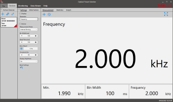
Measurement Panel: The Measurement Panel displays the frequency data or numeric counts as set in the settings panel.
Click to Enlarge
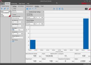
Measurement Statistics: The numerical statistics for a pre-determined measurement period are calculated. The panel displays the analyzed values in a bar graph and the results as numerical values.
Click to Enlarge
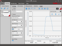
Graph Panel: The Graph Panel shows the signal over time either as frequency or counts.
Click to Enlarge
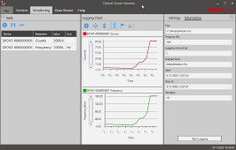
Data Logging: The Logging Chart enables long-term measurement and simultaneous recording from up to eight photon counters. Data can be saved as .csv files for later processing while measurement results are displayed in a graph in real time.
Click to Enlarge
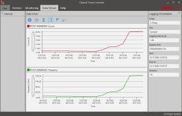
Data Viewer: The logged data can be loaded and displayed.
Click to Enlarge
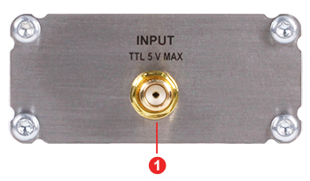
SPCNT Side panel Left
Click to Enlarge
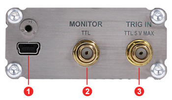
SPCNT Side Panel Right
| Callout | Description |
|---|---|
| 1 | SMA Input (0 - 5 V) |
| Callout | Description |
|---|---|
| 1 | USB 2.0 (Mini-B) Connector (5 V Power Supply) |
| 2 | SMA Monitor Output (0 - 5 V) |
| 3 | SMA Trig In (Gate via TTL) (0 - 5 V) |
| Posted Comments: | |
Chang-Wei Cheng
(posted 2024-05-03 13:20:37.23) Dear Thorlabs services,
I have a single photon detectors (SPD, pulse width is about 2 ns and amplitude is 0.6-1V). Recently, we want to buy a single photon counting module.
Is Your product SPCNT compatible with our SPD? hkarpenko
(posted 2024-05-03 07:53:13.0) Dear customer,
thank you very much for your feedback. It depends on several specifications of your current SPD, whether the SPCNT single photon counting module is compatible with it. I will contact you directly to discuss this further with you. user
(posted 2023-10-19 18:41:49.393) Good evening,
I would like to know if two SPCNT could be used to make time-correlated single photon counting.
Thanks in advance. |

- Connect to the Output of a Single Photon Detector to Monitor Single Photon Counts
- Compatible with the SPDMA and SPDMHx Single Photon Detectors
Thorlabs' SPCNT Single Photon Counting Device recognizes signal pulses originating from a connected single photon detector. The results are shown numerically as counts or frequency on the built in display or sent to a connected PC for display and analysis.
The SPCNT photon counter includes a USB 2.0 type A to mini-B cable to connect to a PC or to a 5 V power supply such as Thorlabs' DS5 power supply.
The ECM100 and ECM225 Aluminum Side Clamps can be used to secure the SPCNT device for convenient laboratory viewing.

- Mount Thorlabs' Rectangular Electronics Housings on a Ø1/2" Post
- ECM100 Attaches to the Sides of the SPCNT Photon Counter Housing
- ECM225 Attaches to the Bottom of the SPCNT Photon Counter Housing
The ECM225 and ECM100 are two of Thorlabs' family of aluminum side clamps that are designed to securely mount Thorlabs' rectangular electronics housings.
The ECM225 has three #8 (M4) counterbored through holes, and the ECM100 has one. The counterbored through holes allow the clamps to be mounted on a Ø1/2" post or any surface with an 8-32 (M4) tap. The clamp must be mounted via the counterbored through hole before the electronics housing is attached, as the counterbore will not be accessible once the housing is secured in the clamp.
 Products Home


 Zoom
Zoom
 Single Photon Counting Device