 Products Home / Fiber Components / Fiber Optic Attenuators / Electronic Variable Optical Attenuators, Voltage Controlled & SM Fiber Coupled
Electronic Variable Optical Attenuators, Voltage Controlled & SM Fiber Coupled
- MEMS-Based Control of Optical Power in Single Mode Fiber
- Six Models Cover Wavelengths from 488 nm to 2300 nm
- Optical Attenuation up to >30 dB or >25 dB
- Modulation up to 1 kHz
- MEMS-Based Electronic Control of Optical Power in Fiber
- Five Models Cover Wavelengths from 450 nm to 1650 nm
- DC to 1 kHz Bandwidth
- Maximum Attenuation >20 dB or >30 dB
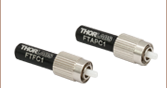
V1550A
Electronic VOA, FC/APC Version
(1250 nm - 1650 nm Model)
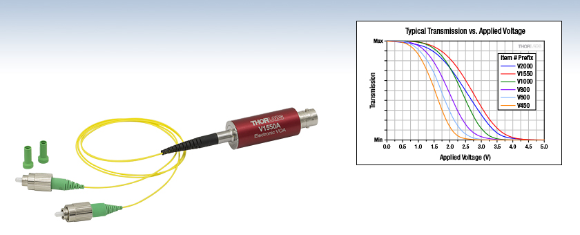
Typical transmission as a function of applied voltage for all models, which are offered with FC/PC or FC/APC connectors.


Please Wait
| Quick Links | |||
|---|---|---|---|
| Item # Prefix | Wavelength Range | Max Attenuation |
Connector Options |
| V450 | 488 - 600 nma | >30 dB | FC/APC or FC/PC |
| V600 | 600 - 780 nm | ||
| V800 | 780 - 980 nm | ||
| V1000 | 980 - 1250 nm | ||
| V1550 | 1250 - 1650 nm | >25 dB | |
| V2000 | 1700 - 2300 nm | ||
| Fiber Optic Attenuator Selection Guide | |
|---|---|
| SM |
Electronic VOAs for System Integration |
| Digital VOAs | |
| Tabletop EVOAs with Power Lock | |
| Manually Variable Attenuators | |
| Fixed-Value Attenuators | |
| MM | Fixed-Value Attenuators |
| Manually Variable Attenuators | |
| PM |
Electronic VOAs for System Integration |
| Manually Variable Attenuators | |
Click to Enlarge
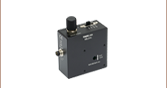
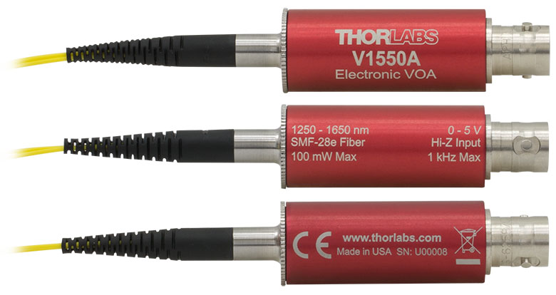
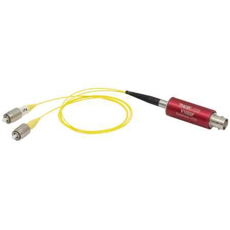
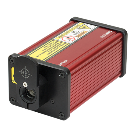
A female BNC connector is located on one end of the barrel, and fiber leads with either FC/APC or FC/PC connectors are integrated into the opposite end. Each barrel is engraved with the shown information for convenience.
Features
- MEMS-Based Devices Provide Attenuation up to >30 dB or >25 dB (See Table to the Right)
- Single Mode Operation
- Control Optical Power by Applying 0 to 5 V Signal
- Six Operating Wavelength Ranges Available (See Table to the Right)
- Maximum Optical Input Power up to 100 mW, Depending on Model
- Modulation up to 1 kHz
- BNC Input is Protected from Electrostatic Discharge
Thorlabs' Fiber-Coupled Electronic Variable Optical Attenuators (VOAs) are microelectromechanical system (MEMS) based devices that provide attenuation up to >30 dB or >25 dB, depending on the model. The optical fiber built into each device is single mode over the specified operating wavelength range. Driving voltages of 0 to 5 V control optical transmission, which decreases with applied voltage. These high-speed VOAs support modulation up to 1 kHz. Protection diodes integrated into the design limit the input voltage to protect the VOA from ESD, as well as from other over-voltage and under-voltage events.
A plot of the typical relationship between the applied voltage and the optical transmission for each electronic VOA model is included in the Specs tab. Most voltage sources, including power supplies, function generators, and digital-to-analog converters (DACs), can be used to control these electronic VOAs. Use a BNC cable (not included) to connect the electronic VOA to the voltage source. The MEMS VOA is an electrostatic device that inherently requires no current. However, the protection circuitry can draw up to 100 µA for applied voltages of 5 V.
Either of the unit's 50 cm long fiber leads can be used as the input, as performance is similar in both directions. However, you may find that one of the connectors provides a lower loss connection in your set-up due to the random nature of core alignment. As shown in the image above, the barrel of each electronic VOA is etched, for convenience, with information such as the operating wavelength range, maximum optical input power, maximum modulation bandwidth, and driving voltage range. These VOAs are designed for use with optical fiber that is single mode within the operating range. Please see the Specs tab for information on the single mode fibers integrated into each model.
Electronic VOAs with polarization-maintaining (PM) fiber and FC/APC connectors are available here.
Fiber Core Alignment
Note that the minimum attenuation for these devices depends on excellent core-to-core alignment when the connectors are mated. This is even more crucial for shorter wavelength VOAs with smaller fiber core diameters. If they are not perfectly aligned, the insertion loss can easily go up many decibels above the specification. Since we cannot control the fibers that are used to connect to these devices, we test the devices for minimum attenuation by using a setup that actively aligns the cores of the fibers and minimizes the connector loss. From this, we obtain the minimum attenuation possible for each device. Unless the user also does the same, or better yet, fusion splices the fibers, they may not achieve the specified minimum attenuation.
Fiber Cleanliness
Fibers with smaller core diameters (<5 μm) must be kept extremely clean because the presence of material at fiber-fiber interfaces, combined with the high optical power density, can lead to significant optical damage. This is especially true at short wavelengths where the photon energy is also high. If care is not taken, the end of the fiber at the FC/PC or FC/APC connector can sustain damage that will reduce the coupling efficiency or possibly even prevent coupling altogether. This type of damage usually requires re-polishing or replacement of the connector. Depending on the specific conditions, this can even happen at average power levels less than 10 mW. Additional caution should be taken with pulsed lasers, since the peak power can be much higher than the average power. Please make sure the fiber ends are kept as clean as possible and cleaned every time a connection is made.
Maximum Optical Input Power
Due to their small fiber core diameters, as well as the high photon energies for light in the 488 nm to 600 nm range, the damage thresholds for the V450A and V450F attenuators are lower than for our other models. To avoid damage to the exposed fiber end faces and internal components, the optical input power should never exceed 20 mW. If you observe decreased transmission or visible damage to the fiber core at the connector faces, re-polishing or replacing the connectors may restore performance if no internal damage has occurred.
| Item # | V450A | V450F | V600A | V600F | V800A | V800F | V1000A | V1000F | V1550A | V1550F | V2000A | V2000F | |
|---|---|---|---|---|---|---|---|---|---|---|---|---|---|
| Wavelength Range | 488 to 600 nma | 600 to 780 nm | 780 to 980 nm | 980 to 1250 nm | 1250 to 1650 nm | 1700 to 2300 nm | |||||||
| Attenuationb | Max | >30 dB | >25 dB | ||||||||||
| Min | 3.0 dB | 2.5 dB | 2.0 dB | 1.5 dB | |||||||||
| Optical Input Power (Max) | 20 mWc | 100 mW | |||||||||||
| Optical Return Loss | >30 dB | ||||||||||||
| Fiber Connectorsd | FC/APC | FC/PC | FC/APC | FC/PC | FC/APC | FC/PC | FC/APC | FC/PC | FC/APC | FC/PC | FC/APC | FC/PC | |
| Device Fiber Typee | 460HP | 630HP | 780HP | HI1060-J9 | SMF-28 Type | SM2000 | |||||||
| Modulation Signal Input | |||||||||||||
| Input Voltage | 0 to 5 V (Absolute Max: 10 V, 5 mA) | ||||||||||||
| Input Impedance | High-Z | ||||||||||||
| Bandwidth | DC to 1 kHz | ||||||||||||
| Input Voltage Connector | Female BNC | ||||||||||||
| Physical Specifications | |||||||||||||
| Dimensions | Diameter: 15.7 mm (0.62") Length Excluding Fiber Leads: 50.1 mm (1.97") Length of the Fiber Leads: 50.0 cm ± 10.0 cm |
||||||||||||
| Operating Temperature | 0 °C to 40 °C | ||||||||||||
| Storage Temperature | -20 °C to 70 °C | ||||||||||||
| Relative Humidity | 5% to 85% (Non-Condensing) | ||||||||||||
Click to Enlarge
Typical Optical Transmission as a Function of Applied Voltage
(Test Wavelengths: 520 nm for V450 models; 635 nm for V600 models; 850 nm for V800 models; 1060 nm for V1000 models; 1550 nm for V1550 models; 2000 nm for V2000 models)
Click to Enlarge
The supply current required to drive these electronic VOAs over the 0 to 5 V operating range is plotted above.
Click for Details
Mechanical Drawing of the Fiber-Coupled VOA Package

Janis Valdmanis, Ph.D. Optics
Ultrafast Optoelectronics
General Manager
Custom and OEM Options
When your application requirements are not met by our range of catalog products or their variety of user-configurable features, please contact me to discuss how we may serve your custom or OEM needs.
Request a Demo Unit
Explore the benefits of using a Thorlabs high-speed instrument in your setup and under your test conditions with a demo unit. Contact me for details.
![]()
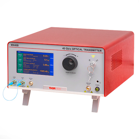
Click to Enlarge
The MX40B Digital Reference Transmitter
Design, Manufacturing, and Testing Capabilities
Thorlabs' Ultrafast Optoelectronics Team designs, develops, and manufactures high-speed components and instrumentation for a variety of photonics applications having frequency responses up to 110 GHz. Our extensive experience in high-speed photonics is supported by core expertise in RF/microwave design, optics, fiber optics, optomechanical design, and mixed-signal electronics. As a division of Thorlabs, a company with deep vertical integration and a portfolio of over 20,000 products, we are able to provide and support a wide selection of equipment and continually expand our offerings.
Our catalog and custom products include a range of integrated fiber-optic transmitters, modulator drivers and controllers, detectors, receivers, pulsed lasers, variable optical attenuators, and a variety of accessories. Beyond these products, we welcome opportunities to design and produce custom and OEM products that fall within our range of capabilities and expertise. Some of our key capabilities are:
- Detector and Receiver Design, to 70 GHz
- Fiber-Optic Transmitter Design, to 110 GHz
- RF & Microwave Design and Simulation
- Design of Fiber-Optic and Photonics Sub-Assemblies
- High-Speed Testing, to 110 GHz
- Micro-Assembly and Wire Bonding
- Hermetic Sealing of Microwave Modules
- Fiber Splicing of Assemblies
- Custom Laser Engraving
- Qualification Testing
Overview of Custom and Catalog Products
Our catalog product line includes a range of integrated fiber-optic transmitters, modulator drivers and controllers, detectors, pulsed lasers, and accessories. In addition to these, we offer related items, such as receivers and customized catalog products. The following sections give an overview of our spectrum of custom and catalog products, from fully integrated instruments to component-level modules.
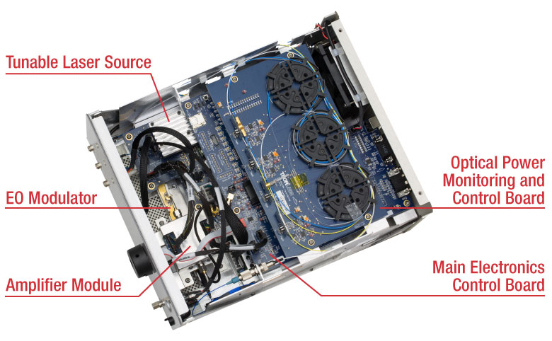
Fiber-Optic Instruments
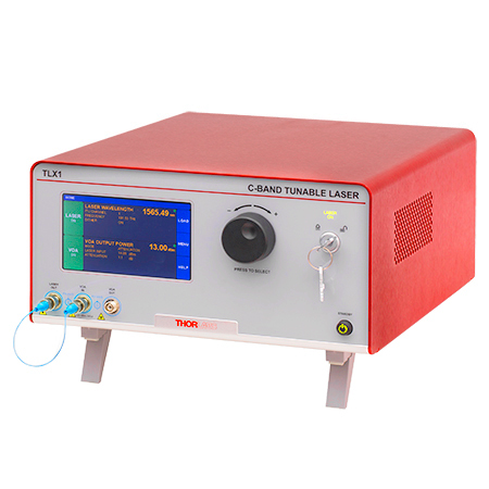
To meet a range of requirements, our fiber-optic instruments span a variety integration levels. Each complete transmitter includes a tunable laser, a modulator with driver amplifier and bias controller, full control of optical output power, and an intuitive touchscreen interface. The tunable lasers, modulator drivers, and modulator bias controllers are also available separately. These instruments have full remote control capability and can be addressed using serial commands sent from a PC.
- Fiber-Optic Transmitters, to 110 GHz
- Linear and Digital Transmitters
- Electrical-to-Optical Converters, to 110 GHz
- Modulator Drivers
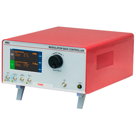
- Modulator Bias Controllers
- C- and L-Band Tunable Lasers
Customization options include internal laser sources, operating wavelength ranges, optical fiber types, and amplifier types.
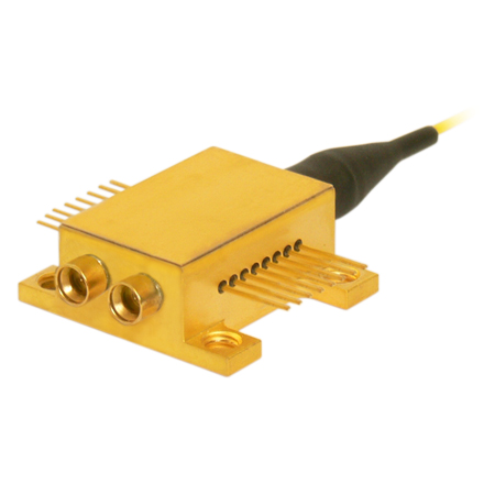
Fiber-Optic Components
Our component-level, custom and catalog fiber-optic products take advantage of our module design and hermetic sealing capability. Products include detectors with frequency responses up to 50 GHz, and we also specialize in developing fiber-optic receivers, operating up to and beyond 40 GHz, for instrumentation markets. Closely related products include our amplifier modules, which we offer upon request, variable optical attenuators, microwave cables, and cable accessories.
- Hermetically-Sealed Detectors, to 50 GHz
- Fiber-Optic Receivers, to 40 GHz
- Amplifier Modules
- Electronic Variable Optical Attenuators
- Microwave Cables and Accessories
Customization options include single mode and multimode optical fiber options, where applicable, and detectors optimized for time or frequency domain operation.
Free-Space Instruments
Our free-space instruments include detectors with frequency responses around 1 GHz and pulsed lasers. Our pulsed lasers generate variable-width, nanosecond-duration pulses, and a range of models with different wavelengths and optical output powers are offered. User-adjustable repetition rates and trigger in/out signals provide additional flexibility, and electronic delay-line products enable experimental synchronization of multiple lasers. We can also adapt our pulsed laser catalog offerings to provide gain-switching capability for the generation of pulses in the 100 ps range.
- Pulsed Lasers with Fixed 10 ns Pulse Duration
- Pulsed Lasers with Variable Pulse Width and Repetition Rates
- Electronic Delay Units to Synchronize NPL Series Pulsed Lasers
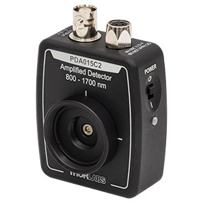
- Amplified Detectors
Customization options for the pulsed lasers include emission wavelength, optical output powers, and sub-nanosecond pulse widths.

| Posted Comments: | |
Fabrice Pancher
(posted 2024-06-14 13:48:46.55) Two questions about the V1550A model:
1- Are the attenuation factors repeatable for the same input voltage values? I mean, if a voltage V1 is applied giving an attenuation A1, and then a voltage V2 giving an attenuation A2, and then V3, etc... After this, if voltage V1 is applied again, will it give exactly the attenuation A1, or is there a phenomenon such as hysteresis ? Also, does the attenuators requires recalibration from time to time ?
2-Do you have any recommended power supply models, knowing that we need to be able to control this power supply remotely (e.g., via a serial port)?"
Thanks in advance. cdolbashian
(posted 2024-06-24 04:24:02.0) Thank you for reaching out with this inquiry. I will answer each of your questions below. 1. As these are MEMS based systems used in conjunction with single mode fiber coupling, we cannot guarantee exactly repeatable attenuation. 2.You can use any supply which can provide the appropriate voltage for the MEMS via a standard BNC cable. I have contacted you directly to discuss your questions in more detail. user
(posted 2024-06-10 16:37:25.12) I am interested in V1550A but would like to know more information regarding the bandwidth. What does modulation upto 1kHz mean? Do you have any information regarding the rise-time (or fall-time) when a given voltage is applied to the VOA? Could you share a more detailed datasheet on the temporal response please? jpolaris
(posted 2024-06-17 04:02:26.0) Thank you for contacting Thorlabs. V1550A is able to accept modulation input signals from DC (0 Hz modulation) up to 1 kHz while maintaining its specifications. This just means that if you were to connect V1550A up to some kind of function generator, the specified bandwidth spans DC to 1 kHz. This is the "3 dB" bandwidth (f_3dB), by the way. That is, you can estimate the small signal rise time by taking 0.35/(f_3dB). In the case of V1550A, this is ~350 μs for sine wave signals. If you are using other waveforms (e.g., square), you can expect the rise time to increase ↔ smaller bandwidth. I have reached out to you directly to inquire more about your application and possibly share any relevant temporal data that may be useful. Silas Eul
(posted 2024-02-29 15:19:27.37) Hello,
I noticed that MEMS based eVOAS of other vendors are specified with polarisation dependent losses.
Do your eVOAS also exhibit polarisation dependent losses? If yes, are they dependent on voltage/ current? Do you have specifications/measurements regarding this effect?
Best regards,
Silas Eul cdolbashian
(posted 2024-03-15 01:29:34.0) Thank you for reaching out to us Silas. While we do not have full characterizations of the PDL, we do have some data as a function of the total attenuation. I have shared these data with you via email. Silas Eul
(posted 2024-02-29 12:20:43.54) Do you have any Drivers/ variable voltage supplies for the eVOAS? Maybe even Thorlabs KCubes or similiar which are compatible?
Background:
I need to regulate the applied voltage level on a slow timescale, based on evaluated experiemental data, via a computer (preferabbly with a python interface). jpolaris
(posted 2024-03-01 06:12:15.0) Thank you for contacting Thorlabs. These EVOAs have a female BNC input that can be connected to a function generator. The input voltage range is 0 V - 5 V (absolute max: 10 V, 5 mA), and they have a high-Z input impedance. They function over DC - 1 kHz. At this moment we do not offer a single solution from our catalog that would allow you to interface with a PC/ Python. I have reached out to you directly to discuss further. user
(posted 2023-10-10 15:38:14.177) I have two questions about these:-
1) Being based on MEMS blocking the beam in some way (?), how sensitive is the attenuation to vibrations ?
2) How long does it take to change the attenuation from an existing value to a new value ? ksosnowski
(posted 2023-10-13 04:19:05.0) Thanks for reaching out to Thorlabs. While we do not expect the VOA's mirror to be very easily damaged by vibrations, as this is a mobile component it is possible to couple vibrations to the mirror which would effect the attenuation due to internal coupling changes. The switching time can be estimated from the 1kHz analog bandwidth: we expect t_rise for a small signal to be roughly 0.35/bandwidth or 350us. For none-sine waveforms you may expect a lower bandwidth due to the higher frequency components present. I have reached out directly to discuss your application in further detail. Yoshi Arita
(posted 2023-09-18 11:16:31.22) Hello,
We are interested in purchasing a customised V800 with the following changes:
Fibre connectors are to be SC/APC at both ends.
The total length is option (1) for 30 cm +/ 1cm and option (2) for 52.5 cm +/- 1 cm.
So, we want to purchase two VoA fibres (30 cm and 52.5 cm in fibre length) with SC/APC connectors at both ends.
Thank you!
Yoshi Kevin Sin
(posted 2023-01-30 17:27:00.3) Hi,
We would be interested in ordering 5x V1550A but with a multimode interface. Is this possible?
How much would it cost and what is the lead time? jdelia
(posted 2023-02-06 02:06:12.0) Thank you for contacting Thorlabs. I have reached out to you directly to discuss the feasibility of this custom item request. user
(posted 2022-02-21 10:25:05.37) Hi
What is the maximum available input power?
Best regards jdelia
(posted 2022-02-23 10:34:49.0) Thank you for contacting Thorlabs. These attenuators have a maximum optical input power of 100 mW and a maximum input voltage of 5 V. Please feel free to reach out to techsupport@thorlabs.com with any further questions. alexey.kokhanovskiy
(posted 2018-09-12 12:58:11.63) Hello,
Could you provide information about PM version of electronic variable optical attenuators V1000A and V1550A. Is it possible to make V1000A with PM980 fiber?
With respect,
Alexey Kokhanovskiy YLohia
(posted 2018-09-18 09:16:43.0) Hello Alexey, we already manufacture a PM version of the V1000A -- the part number for this is V1000PA and it contains PM980-XP fibers. hmcgui
(posted 2017-06-27 14:32:33.16) I am also interested in a PM version. Please let me know when one will be available. tfrisch
(posted 2017-08-03 11:58:37.0) Hello, thank you for contacting Thorlabs. PM versions of these VOAs have been submitted for release as stock items, and I expect they will be available soon. I will reach out to you with more details. massey4
(posted 2017-06-02 07:15:04.803) Is there a PDF manual for the device or only the spec sheet?
What is the absolute maximum allowed applied voltage? nbayconich
(posted 2017-06-15 01:42:54.0) Thank you for contacting Thorlabs. The suggested applied voltage for these variable optical attenuators is 5V (1 mA. These VOA's can be operated up to 10V. There is a shunting circuit between the BNC connector and the MEMS VOA so this can be used at 10 Volts without damaging the circuit.
Currently we have a brief operating guide in the .pdf spec sheet available to download. To operate the VOA connect the optical input and output to the respective fiber leads on the unit. Either of the unit’s fiber leads can be used as the input, as performance is similar in both directions. Use a BNC cable to connect a power supply or other voltage source to the unit, and then apply 0 to 5 V to control the attenuation. Optical transmission decreases with applied voltage. A techsupport representative will contact you directly. f.m.j.cozijn
(posted 2017-05-12 11:56:34.4) This is an excellent product and I would order one right away if it was a PM version. Is there a PM version planned in the near future? tfrisch
(posted 2017-05-17 04:34:12.0) Hello, thank you for contacting Thorlabs. I will reach out to you directly about availability of PM versions. parkse
(posted 2017-04-17 22:19:14.997) Please produce VOS for PM fiber. tfrisch
(posted 2017-04-28 03:26:20.0) Hello, thank you for contacting Thorlabs. I have posted your request in our internal engineering forum. I agree that this would be a useful extension of this product line. |
- Attenuation Range: 3.0 dB to >30 dB
- Maximum Optical Input Power of 20 mW
- Integrated 460HP Single Mode Fiber Pigtails with FC/APC or FC/PC Connectors
The V450A and V450F are fabricated with and designed for use with optical fiber that is single mode within its operating range. An example of compatible single mode optical fiber is 460HP. Please note that the minimum attenuation is highly dependent on connector alignment, especially at shorter wavelengths. The given specifications assume good core-to-core alignment at the connector.
Due to their small fiber core diameters, as well as the high photon energies for light in the 488 nm to 600 nm range, the damage thresholds for these attenuators is lower than for our other models. To avoid damage to the exposed fiber end faces and internal components, the optical input power should never exceed 20 mW. If you observe decreased transmission or visible damage to the fiber core at the connector faces, re-polishing or replacing the connectors may restore performance if no internal damage has occurred.
- Attenuation Range: 2.5 dB to >30 dB
- Maximum Optical Input Power of 100 mW
- Integrated 630HP Single Mode Fiber Pigtails with FC/APC or FC/PC Connectors
The V600A and V600F are fabricated with and designed for use with optical fiber that is single mode within its operating range. An example of compatible single mode optical fiber is 630HP. Please note that the minimum attenuation is highly dependent on connector alignment, especially at shorter wavelengths. The given specifications assume good core-to-core alignment at the connector.
- Attenuation Range: 2.0 dB to >30 dB
- Maximum Optical Input Power of 100 mW
- Integrated 780HP Single Mode Fiber Pigtails with FC/APC or FC/PC Connectors
The V800A and V800F are fabricated with and designed for use with optical fiber that is single mode within its operating range. An example of compatible single mode optical fiber is 780HP. Please note that the minimum attenuation is highly dependent on connector alignment. The given specifications assume good core-to-core alignment at the connector.
- Attenuation Range: 2.0 dB to >30 dB
- Maximum Optical Input Power of 100 mW
- Integrated HI1060-J9 Single Mode Fiber Pigtails with FC/APC or FC/PC Connectors
The V1000A and V1000F are fabricated with and designed for use with optical fiber that is single mode within its operating range. An example of compatible single mode optical fiber is HI1060-J9. Please note that the minimum attenuation is highly dependent on connector alignment. The given specifications assume good core-to-core alignment at the connector.
- Attenuation Range: 1.5 dB to >25 dB
- Maximum Optical Input Power of 100 mW
- Integrated SMF-28 Type Single Mode Fiber Pigtails with FC/APC or FC/PC Connectors
The V1550A and V1550F are fabricated with and designed for use with optical fiber that is single mode within its operating range. An example of compatible single mode optical fiber is SMF-28 Ultra. Please note that the minimum attenuation is highly dependent on connector alignment. The given specifications assume good core-to-core alignment at the connector.
- Attenuation Range: 1.5 dB to >25 dB
- Maximum Optical Input Power of 100 mW
- Integrated SM2000 Single Mode Fiber Pigtails with FC/APC or FC/PC Connectors
The V2000A and V2000F are fabricated with and designed for use with optical fiber that is single mode within its operating range. An example of compatible single mode optical fiber is SM2000. Please note that the minimum attenuation is highly dependent on connector alignment. The given specifications assume good core-to-core alignment at the connector.