 Products Home
High-Load Pitch and Yaw Platforms
- Low Profile: 25.0 mm (0.98") Height
- ±2.5° Pitch, ±4.0° Yaw
- Various Adjuster Options Available
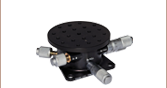
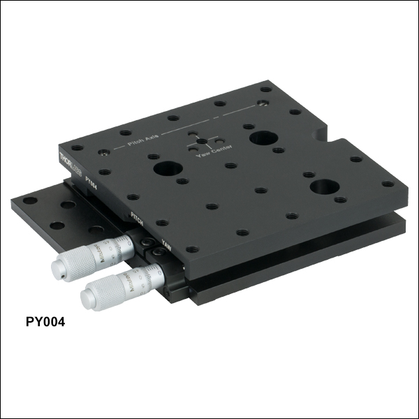
PY004
Pitch and Yaw Platform
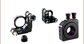
Pitch Adjuster
Yaw Adjuster
Yaw
Pitch
Application Idea
PY004 Pitch/Yaw Platform with HeNe Laser Mounted in V-Clamp
Yaw Adjuster Mount
Pitch Adjuster Mount
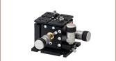
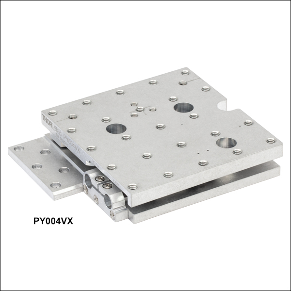
PY004VX
Vacuum Pitch and Yaw Platform
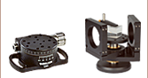
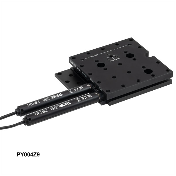
PY004Z9
Pitch and Yaw Platform with DC Servo Actuators
Pitch Adjuster
Yaw Adjuster


Please Wait
| Table 1.1 Key Specificationsa | ||||
|---|---|---|---|---|
| Item # | PY004(/M) | PY004Z9(/M) | PY004VX(/M) | |
| Adjustment Range | Pitch: ±2.5° Yaw: ±4.0° |
|||
| Minimum Incremental Movement | Pitch: 9 arcsecb Yaw: 16.2 arcsecb |
Pitch: 7.13 arcsec Yaw: 15.71 arcsec |
N/Ac | |
| Crosstalk | <0.05° (3 arcmin) | |||
| Horizontal Load Capacity (Max)d | 5.0 kg (11.0 lbs) | 2.0 kg (4.4 lbs) | 5.0 kg (11.0 lbs) | |
| Deck Height | 25.0 mm (0.98") | |||
| Construction | Black Anodized Aluminum | Unanodized Aluminum | ||
| Vacuum Rating | - | 10-6 Torre | ||
| Maximum Bakeout Temperature | - | 130 °Cc | ||
| Operating Temperature | 5 °C to 40 °C (41 °F to 104 °F) | |||
| Included Drives | High-Resolution Micrometers (Qty. 2) | Z912B DC Servo Actuators (Qty. 2) | - | |
Features
- Pitch and Yaw Adjustment
- 1/4"-20 (M6 x 1.0) Tapped Holes with 1.00" (25.0 mm) Spacing
- 0.98" (25.0 mm) Deck Height
- Black Anodized Aluminum (Item #s PY004(/M) and PY004Z9(/M)) or Unanodized Aluminum (Item # PY004VX(/M)) Construction
- Vacuum Compatibility Down to 10-6 Torr (Item # PY004VX(/M))
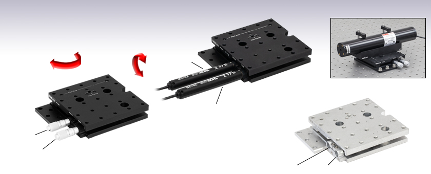
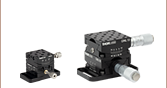
The High-Load Pitch and Yaw Platforms provide ±2.5° of adjustment in pitch and ±4.0° in yaw. They are designed for use with up to 5.0 kg (11.0 lb) loads, such as lasers, cameras, and 3-axis stages (See Figure 1.2). The top platform is equipped with an array of 24 1/4"-20 (M6 x 1.0) threaded mounting holes with 1.00" (25.0 mm) spacing. The actual maximum load will depend on the positioning of the load on the platform. The maximum horizontal load capacity can also be limited by the actuator used with the stage (click here for details).
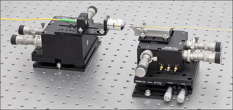
Click to Enlarge Figure 1.2 Two MAX312D 3-Axis Stages Mounted on Two PY004 Stages
Actuator Options
The high-resolution micrometers incorporated into the PY004(/M) stage provide positioning accuracy within 9 arcseconds in pitch and 16.2 arcseconds in yaw. Each revolution of a micrometer gives an angular movement of 0.25° in pitch or 0.45° in yaw. Additionally, these platforms are compatible with other micrometers with a Ø3/8" (Ø9.5 mm) mounting barrel. The stage can also be motorized using our 1/2" travel actuators with Ø3/8" mounting barrels, such as Thorlabs Z912B DC Servo Actuators or ZST213B Stepper Motor Actuators (See Figure 1.4), one for each axis. Alternatively, we offer a motorized PY004Z9(/M) version of the stage with two Z912B DC Servo Actuators included. If desired, the Z912B actuators can be replaced by any manual or motorized actuators with a Ø3/8" (Ø9.5 mm) barrel, including stepper motor actuators and manual micrometers.
The vacuum-compatible PY004VX(/M) platform can be adjusted using our 1/2" travel actuators with Ø3/8" mounting barrels, such as the Thorlabs PIA13VF Vacuum-Compatible Piezo Inertia Actuator or Z912BV Vacuum-Compatible DC Servo Motor Actuator (sold below). Alternatively, a manual vacuum-compatible actuator can be built, using an F25USA1 Barrel Adapter, LN25100 Lock Nut, a POLARIS-N5 Knob, and an F25US200V Vacuum Adjuster (sold below).
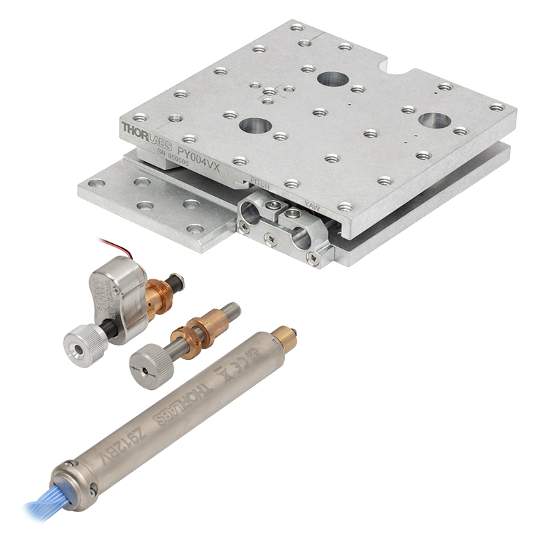
Click to Enlarge
Figure 1.3 PY004VX(/M) Stage Actuator Options (Sold Separately)
Mounting Options
These stages can be mounted directly to a metric or imperial optical table or breadboard using five 1/4" (M6) through mounting holes or the 1/4" (M6) mounting slot. The stages also have three counterbored 1/4" (M6) holes that are revealed by rotating the top plate of the platform. These holes allow the unit to be mounted with the top platform holes in line with the work surface hole pattern or midway off the table's hole pattern. Alternatively, the PY004(/M) platform can be mounted using CL6 clamps secured to the relief cut along the bottom of the stage, and CL6V vacuum-compatible clamps can be used to mount the PY004VX(/M) platform.
Vacuum Compatibility
The PY004VX(/M) platform is a vacuum-compatible version of the PY004(/M) pitch and yaw platform with identical mounting features, accomplished by using vacuum-compatible internal components. Each PY004VX(/M) platform is assembled in a clean environment and double vacuum bagged. Prior to use in a vacuum system, the stages can be baked to remove excess moisture and surface contaminants; however, please note that the maximum baking temperature is 130 °C (with manual vacuum adjusters or PIA13VF actuator) or 85 °C (if using the Z912BV actuator). The platform can be mounted to a breadboard using Thorlabs' CL6V vacuum-compatible clamps and vacuum-compatible fasteners. Thorlabs offers vacuum-compatible breadboards, screws, and other optomechanics that can be can be used with the stage.
Controller Options
When using platforms with servo motors (e.g., PY004Z9(/M)), Thorlabs recommends using two KDC101 DC Servo Controllers (available below), one for each axis. The latest version of the Kinesis software can be downloaded here. Firmware version 2.2.8 or higher and Kinesis software version 1.14.44 or higher are required for using the KDC101 with the PY004Z9(/M) platforms. Please see the Kinesis Software and Kinesis Tutorial tabs for details. For more information on recommended controllers for particular actuators, see Table G4.1.
Note: PY004VX(/M) units are shipped without actuators and locked in position with transit screws. Two actuators are required. These screws should not be removed until the actuators are correctly fitted to the unit.
| Table 2.1 Specifications | ||||
|---|---|---|---|---|
| Item # | PY004(/M) | PY004Z9(/M) | PY004VX(/M) | |
| Adjuster | High-Resolution Micrometers (Qty. 2) | Z912B DC Servo Actuators (Qty. 2) | - | |
| Adjustment Range | Pitch: ±2.5° Yaw: ±4.0° |
|||
| Minimum Incremental Movement | Pitch: 9 arcseca Yaw: 16.2 arcseca |
Pitch: 7.13 arcsec Yaw: 15.71 arcsec |
N/Ab | |
| Bi-directional Repeatability | N/A | Pitch: 27.85 arcsec, Yaw: 4.75 arcsec | N/Ab | |
| Maximum Velocity | N/A | Pitch: 3600 arcsec/s, Yaw: 3600 arcsec/s | N/Ab | |
| Maximum Acceleration | N/A | Pitch: 3600 arcsec/s2, Yaw: 3600 arcsec/s2 | N/Ab | |
| Crosstalk | <0.05° (3 arcmin) | |||
| Weight (with Adjusters, if Applicable) | 679 g (1.5 lbs) | 870 g (1.91 lbs) | 622 g (1.37 lbs) | |
| Horizontal Load Capacity (Max) | 5.0 kg (11.0 lbs)c | 2.0 kg (4.4 lbs)c,d | 5.0 kg (11.0 lbs)c | |
| Vertical Load Capacity (Max), by Distance from Top Platforme | ||||
| 30 mm (1.18") | 1.8 kg (4.0 lbs) | |||
| 50 mm (1.97") | 1.1 kg (2.4 lbs) | |||
| 80 mm (3.15") | 0.7 kg (1.5 lbs) | |||
| Deck Height | 25.0 mm (0.98") | |||
| Actuator Bushing Diameter | 9.5 mm (3/8") | |||
| Construction | Black Anodized Aluminum | Unanodized Aluminum | ||
| Vacuum Rating | - | 10-6 Torrf | ||
| Maximum Bakeout Temperature | - | 130 °C (266 °F)b | ||
| Operating Temperature | 5 °C to 40 °C (41 °F to 104 °F) | |||
| Table 2.2 Compatible Actuators | |||||||
|---|---|---|---|---|---|---|---|
| Item # | Actuator Type | Values with PY004VX(/M) | |||||
| Minimal Incremental Movement | Bi-directional Repeatability | Maximum Velocity | Acceleration | Horizontal Load Capacity (Max)a | Maximum Bakeout Temperature | ||
| Z912B(V) | DC Servo | Pitch: 7.13 arcsec Yaw: 15.71 arcsec |
Pitch: 27.85 arcsec Yaw: 4.75 arcsec |
Pitch: 3600 arcsec/s Yaw: 3600 arcsec/s |
Pitch: 3600 arcsec/s2 Yaw: 3600 arcsec/s2 |
2.0 kg (4.4 lbs)b | 85°C (185 °F) |
| PIA13(VF)c | Piezo Inertia | Pitch: 54 milliarcsec Yaw: 97.2 milliarcsec |
- | 27.7 - 83.1 arcsec/s | - | 5.0 kg (11.0 lbs) | 130 °C (266 °F) |
| Vacuum Adjusterd | Manual | N/Ae | N/A | N/A | N/A | 5.0 kg (11.0 lbs) | 130 °C (266 °F) |
| ZFS13Bc | Compact Stepper | Pitch: 1 milliarcsec Yaw: 1.6 milliarcsec |
- | 2770 arcsec/s | 9000 arcsec/s2 | 1.8 kg (4.0 lbs) | - |
| ZST213Bc | Stepper | - | |||||
Z912B Connector Pin Out
D-Type Male
| Pin | Description | Pin | Description |
|---|---|---|---|
| 1 | Ground (Limit and Vcc) | 9 | Resistive Identification |
| 2 | Forward Limit | 10 | +5 VDC |
| 3 | Reverse Limit | 11 | Encoder Channel A |
| 4 | Reserved for Future Use | 12 | Reserved for Future Use |
| 5 | Motor (-) | 13 | Encoder Channel B |
| 6 | Reserved for Future Use | 14 | Pin 2 Ident EEPROM |
| 7 | Motor (+) | 15 | Pin 1 Ident EEPROM |
| 8 | Reserved for Future Use |
Software
Kinesis Version 1.14.55
The Kinesis Software Package, which includes a GUI for control of Thorlabs' Kinesis system controllers.
Also Available:
- Communications Protocol

Figure 58A Kinesis GUI Screen
Thorlabs offers the Kinesis software package to drive our wide range of motion controllers. The software can be used to control devices in the Kinesis family, which covers a wide variety of motion controllers ranging from small, low-powered, single-channel drivers (such as the K-Cubes®) to high-power, multi-channel benchtop units and modular 19" rack nanopositioning systems (the MMR60x Rack System).
The Kinesis Software features .NET controls which can be used by 3rd party developers working in the latest C#, Visual Basic, LabVIEW™, or any .NET compatible languages to create custom applications. Low-level DLL libraries are included for applications not expected to use the .NET framework and APIs are included with each install. A Central Sequence Manager supports integration and synchronization of all Thorlabs motion control hardware.
By providing this common software platform, Thorlabs has ensured that users can mix and match any of our motion control devices in a single application, while only having to learn a single set of software tools. In this way, it is perfectly feasible to combine any of the controllers from single-axis to multi-axis systems and control all from a single, PC-based unified software interface.
The software package allows two methods of usage: graphical user interface (GUI) utilities for direct interaction with and control of the controllers 'out of the box', and a set of programming interfaces that allow custom-integrated positioning and alignment solutions to be easily programmed in the development language of choice.
Thorlabs' Kinesis software features new .NET controls which can be used by third-party developers working in the latest C#, Visual Basic, LabVIEW™, or any .NET compatible languages to create custom applications.
C#
This programming language is designed to allow multiple programming paradigms, or languages, to be used, thus allowing for complex problems to be solved in an easy or efficient manner. It encompasses typing, imperative, declarative, functional, generic, object-oriented, and component-oriented programming. By providing functionality with this common software platform, Thorlabs has ensured that users can easily mix and match any of the Kinesis controllers in a single application, while only having to learn a single set of software tools. In this way, it is perfectly feasible to combine any of the controllers from the low-powered, single-axis to the high-powered, multi-axis systems and control all from a single, PC-based unified software interface.
The Kinesis System Software allows two methods of usage: graphical user interface (GUI) utilities for direct interaction and control of the controllers 'out of the box', and a set of programming interfaces that allow custom-integrated positioning and alignment solutions to be easily programmed in the development language of choice.
For a collection of example projects that can be compiled and run to demonstrate the different ways in which developers can build on the Kinesis motion control libraries, click on the links below. Please note that a separate integrated development environment (IDE) (e.g., Microsoft Visual Studio) will be required to execute the Quick Start examples. The C# example projects can be executed using the included .NET controls in the Kinesis software package (see the Kinesis Software tab for details).
 |
Click Here for the Kinesis with C# Quick Start Guide Click Here for C# Example Projects Click Here for Quick Start Device Control Examples |
|
LabVIEW
LabVIEW can be used to communicate with any Kinesis-based controller via .NET controls. In LabVIEW, you build a user interface, known as a front panel, with a set of tools and objects and then add code using graphical representations of functions to control the front panel objects. The LabVIEW tutorial, provided below, provides some information on using the .NET controls to create control GUIs for Kinesis-driven devices within LabVIEW. It includes an overview with basic information about using controllers in LabVIEW and explains the setup procedure that needs to be completed before using a LabVIEW GUI to operate a device.
 |
Click Here to View the LabVIEW Guide Click Here to View the Kinesis with LabVIEW Overview Page |
|
| Posted Comments: | |
Pablo Perez-Martin
(posted 2020-09-24 09:58:53.213) Does the PY004/M have a vacuum compatible equivalent? cwright
(posted 2020-09-28 08:28:35.0) Response from Charles at Thorlabs: Hello and thank you for contacting us. Some of our stages can be made vacuum compatible on request and the PY004/M is one of them. We will reach out to you directly regarding the current lead time and pricing. thigulla saikiran
(posted 2020-07-25 01:43:17.787) i want to place that mount in vertical position and the payload on the mount will be around 5Kgs . it can carry the mount load of 5kgs in vertical direction
Regards,
Saikiran DJayasuriya
(posted 2020-08-13 04:34:24.0) Thank you for your inquiry. When mounted vertically the load capacity depends on the load distance from the platform and the load it self. Mounted vertically the maximum load the stage could handle is about 1.8kg approximately and the off axis distance from the platform being 30 mm. David G
(posted 2020-05-21 06:39:57.247) I'm having the same issue as Lawrence (last post below) in understanding how the linear micrometer movement translates to rotation. I also calc that the minimum incremental values (per half division) are twice those stated. Example below is for pitch, but yaw calculation is also wrong.
1 Rev micrometer = 0.5deg = 1800 sec
1 inc micrometer = 1800 sec/50 = 36 sec
1 half inc micrometer = 18 sec (vs 9 sec quoted on website)
Can you clarify? Thanks. DJayasuriya
(posted 2020-06-03 03:52:21.0) Thank you for your inquiry. Due to the mechanism of the stage it wouldn't be a completely linear relationship but between micrometer movement and the rotation.There is a small acute distortion. This also depends how you measure - if the beam is going through the rotation center it will be perfect. In any other cases you will find another numbers as to the rotation of the beam you need to add the movement of the source. If you have any questions please dont hesitate to get in touch with your local technical support team lawrence.berg
(posted 2015-09-15 11:01:19.777) Yet another: Taking pitch on the PY004, minimum incremnental movement is given as 9 arc seconds based on half a division. But at 0.5 degree/rev = 1800 arcsec/rev = 36 arcsec/div. Min inc mov is thus 1/4 division. Am I wrong in assuming 50 divisions/revolution? (Note manual Fig 2.2 implies 100 divisions/revolution also). bwood
(posted 2015-09-17 10:50:44.0) Response from Ben at Thorlabs: Thank you for your feedback messages. The micrometer drives can be removed by loosening a single M3 screw for each actuator, and installing an appropriate Ø3/8" mounting barrel. There is no need to return the stage to be retrofitted. The micrometer itself has a 10µm per division travel, and has a 13mm range. Finally, your calculation does appear to be valid, and I will contact our engineers to clarify this further. I will contact you directly with the results of these discussions. lawrence.berg
(posted 2015-09-15 10:23:24.673) Another question: How much actual travel/revolution is occurring with each micrometer in the PY004 (information needed when looking at motorized options). Thanks lawrence.berg
(posted 2015-09-15 10:01:08.143) Can the PY004 be retrofitted with the motorized micrometer options discussed by the end user? Or must the unit be sent back for retrofit? cflamme
(posted 2014-04-02 09:36:30.877) Does the PY004
have a locking feature?
or do you have a comperable fitures that does cdaly
(posted 2014-04-09 05:16:51.0) Response from Chris at Thorlabs: The PY004 does not have a locking mechanism. While we do have other pitch yaw stages, I'm afraid none of these have this feature either. |

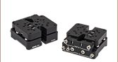
 Zoom
Zoom- Anodized Aluminum Pitch and Yaw Adjustment Stage
- High-Resolution Micrometers Included
- Mounting to Tables and Breadboards Using 1/4" (M6 x 1.0) Mounting Holes or CL6 Table Clamps (Sold Separately)
The PY004(/M) pitch and yaw platform includes high-resolution micrometers and provides ±2.5° of adjustment in pitch and ±4.0° in yaw. It is designed for use with up to 5.0 kg (11.0 lb) loads, such as lasers, cameras, and 3-axis stages. The actual maximum load will depend on the positioning of the load on the platform (click here for details). The top platform is equipped with an array of 24 1/4"-20 (M6 x 1.0) threaded mounting holes with 1.00" (25.0 mm) spacing.
These stages can be mounted directly to a metric or imperial optical table or breadboard using five 1/4" (M6) through mounting holes or the 1/4" (M6) mounting slot. The stages also have three counterbored 1/4" (M6) holes that are revealed by moving the top plate of the platform. These holes allow the unit to be mounted with the top platform holes in line with the work surface hole pattern or midway off the table's hole pattern. Alternatively, the PY004(/M) platform can be mounted using CL6 clamps secured to the relief cut along the bottom of the stage.

 Zoom
Zoom
Click to Enlarge
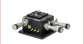
Figure G2.1 Mounting a 3-axis positioner on the PY004Z9 platform results in precision 5-axis control useful in many applications such as fiber alignment.
- Motorized Pitch and Yaw Adjustment via Included DC Servo Actuators
- Maximum Load Capacity: 2.0 kg (4.40 lbs)
- Controllers and Power Supplies Sold Separately
- Mounting to Tables and Breadboards Using 1/4" (M6 x 1.0) Mounting Holes or CL6 Table Clamps (Sold Separately)
Thorlabs' PY004Z9(/M) Motorized Pitch and Yaw Platform provides an adjustment range of ±2.5° and ±4.0° in pitch and yaw, respectively. An array of twenty-four 1/4"-20 (M6) tapped holes allows easy integration with a wide variety of common optomechanical setups. The stage features a maximum load capacity of 2.0 kg (4.4 lbs), making it ideal for use with lasers, cameras, or 3-axis platforms. The actual maximum load will depend on the positioning of the load on the platform (click here for details). The stage requires two controller units and power supplies to operate. For this purpose, we recommend our KDC101

 Zoom
Zoom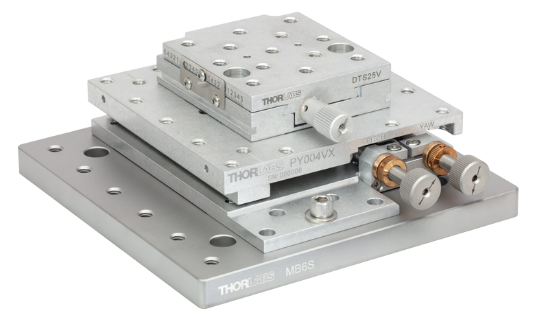
Click to Enlarge
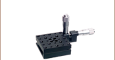
Figure G3.1 PY004VX vacuum pitch/yaw platform with manual vacuum-compatible actuators (built using components sold below) and a DTS25V stage mounted on an MB6S breadboard.
- Vacuum-Compatible Aluminum Pitch and Yaw Adjustment Stage
- Vacuum-Compatible Down to 10-6 Torr
- Packed in a Clean Environment and Double Vacuum-Bagged
- Mounting to Tables and Breadboards Using 1/4" (M6 x 1.0) Mounting Holes or CL6V Table Clamps (Sold Separately)
- Adjusters Available Separately
The PY004VX(/M) pitch and yaw platform provides ±2.5° of adjustment in pitch and ±4.0° in yaw. It is designed for use with up to 5.0 kg (11.0 lb) loads, such as lasers, cameras, and 3-axis stages. The actual maximum load will depend on the positioning of the load on the platform (click here for details) and the actuator used with the stage (see the Specs tab for more information). The top platform is equipped with an array of 24 1/4"-20 (M6 x 1.0) threaded mounting holes with 1.00" (25.0 mm) spacing.
These stages can be mounted directly to a metric or imperial optical table or breadboard using five 1/4" (M6) through mounting holes or the 1/4" (M6) mounting slot. The stages also have three counterbored 1/4" (M6) holes that are revealed by moving the top plate of the platform. These holes allow the unit to be mounted with the top platform holes in line with the work surface hole pattern or midway off the table's hole pattern. Alternatively, the PY004VX(/M) platform can be mounted using CL6V vacuum-compatible clamps secured to the relief cut along the bottom of the stage.
Adjuster Options
The vacuum-compatible PY004VX(/M) platform can be adjusted using our 1/2" travel actuators with Ø3/8" mounting barrels, such as the Thorlabs PIA13VF Vacuum-Compatible Piezo Inertia Actuator or Z912BV Vacuum-Compatible DC Servo Motor Actuator (sold below). Alternatively, a manual vacuum-compatible actuator can be built, using an F25USA1 Barrel Adapter, LN25100 Lock Nut, a POLARIS-N5 Knob, and an F25US200V Vacuum Adjuster (sold below).
Vacuum Compatibility
The PY004VX(/M) platform is a vacuum-compatible version of the PY004(/M) pitch and yaw platform with identical mounting features, accomplished by using vacuum-compatible internal components. Each PY004VX(/M) platform is assembled in a clean environment and double vacuum bagged. Prior to use in a vacuum system, the stages can be baked to remove excess moisture and surface contaminants; however, please note that the maximum baking temperature is 130 °C (with manual vacuum adjusters or PIA13VF actuators) or 85 °C (if using the Z912BV actuators). The platform can be mounted to a breadboard using the 1/4" (M6 x 1.0) mounting holes or Thorlabs' CL6V vacuum-compatible clamps and vacuum-compatible fasteners. Thorlabs offers vacuum-compatible breadboards, screws, and other optomechanics that can be can be used with the stage.
Note: PY004VX(/M) units are shipped without actuators and locked in position with transit screws. Two actuators are required. These screws should not be removed until the actuators are correctly fitted to the unit.
| Table G4.1 Motorized Actuatorsa | ||||||||
|---|---|---|---|---|---|---|---|---|
| Item #b | Photoc | Actuator Type | Travel | Vacuum Rating | Max Speed | Max Acceleration |
Required Controllerd |
|
| PIA13 | 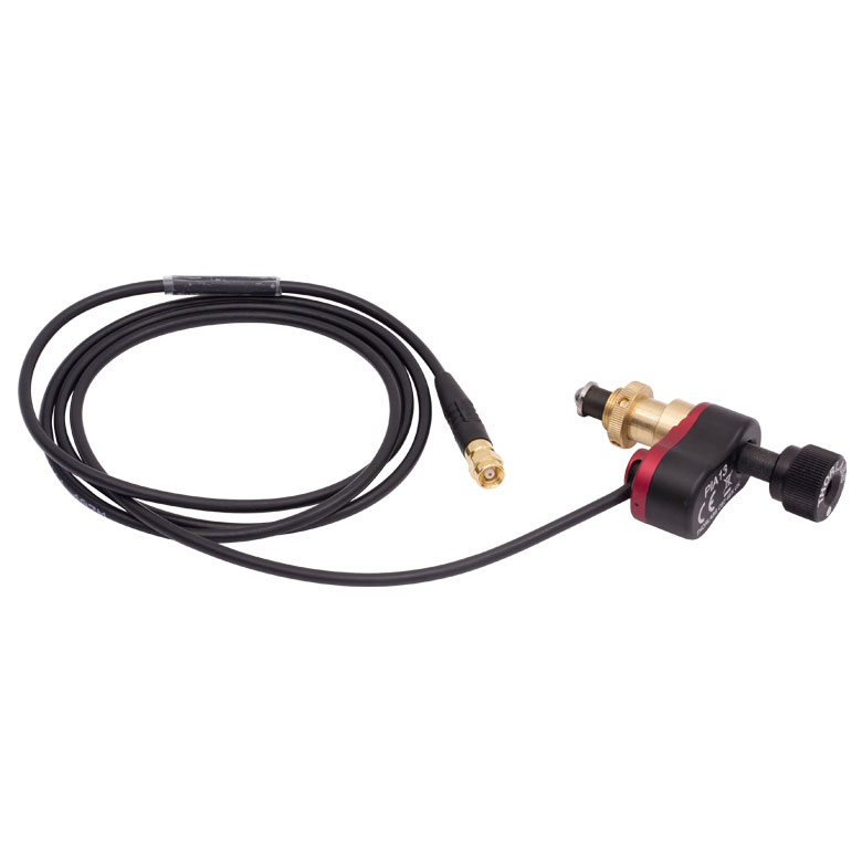 |
Piezo Inertia | 13.0 mm (0.51") | - | ≤3.6 mm/mine | - | KIM001 or KIM101 |
|
| PIA13VF | 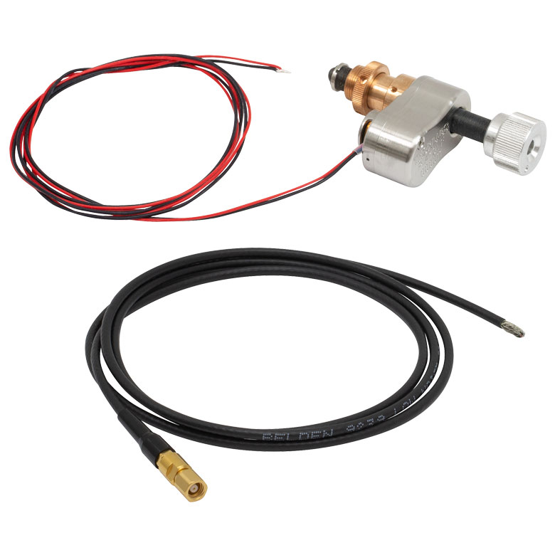 |
Piezo Inertia | 13.0 mm (0.51") | 10-6 Torr | ≤3.6 mm/mine | - | KIM001 or KIM101 |
|
| ZFS13B | 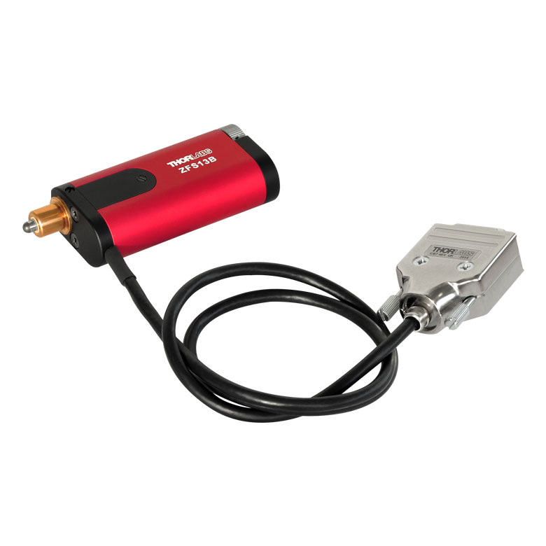 |
2-Phase Stepper Motor | 13.0 mm (0.51") | - | 2.0 mm/s | 10 mm/s2 | KST201 | |
| ZST213B | 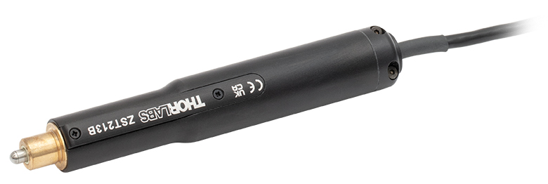 |
2-Phase Stepper Motor | 13.0 mm (0.51") | - | 2.0 mm/s | 10 mm/s2 | ||
| Z912B | 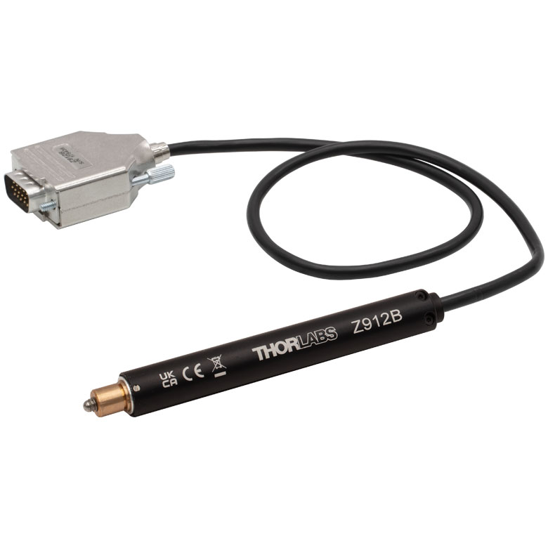 |
DC Servo Motor | 12.0 mm (0.47") | - | 2.6 mm/sf | 4 mm/s2 | KDC101 | |
| Z912BV |  |
DC Servo Motor | 12.0 mm (0.47") | 10-6 Torr | 2.6 mm/sf | 4 mm/s2 | KDC101 | |
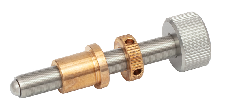 Click to Enlarge
Figure G5.1 Manual Vacuum-Compatible Actuator, built using components sold below
Click to Enlarge
Figure G5.1 Manual Vacuum-Compatible Actuator, built using components sold belowThe vacuum-compatible PY004VX(/M) platform can be adjusted using our 1/2" travel actuators with Ø3/8" mounting barrels, such as the Thorlabs PIA13VF Vacuum-Compatible Piezo Inertia Actuator or Z912BV Vacuum-Compatible DC Servo Motor Actuator (sold below). Alternatively, a manual vacuum-compatible actuator can be built (See Figure G5.1), using an F25USA1 Barrel Adapter, LN25100 Lock Nut, a POLARIS-N5 Knob, and an F25US200V Vacuum Adjuster.
Note: Actuators built using 1/4"-100 vacuum adjusters are compatible with both metric and imperial stages.
| Table G5.2 Vacuum-Compatible Manual Actuatorsa | ||||||||
|---|---|---|---|---|---|---|---|---|
| 1/4"-100 Thread to Ø3/8" Barrel Adapter | 1/4"-100 Lock Nut | Knob for 1/4"-100 Adjusters | 2.00" Long 1/4"-100 Vacuum Adjuster | Vacuum Rating | ||||
| F25USA1 | LN25100 | POLARIS-N5 | F25US200V | 10-6 Torrb | ||||

 Zoom
Zoom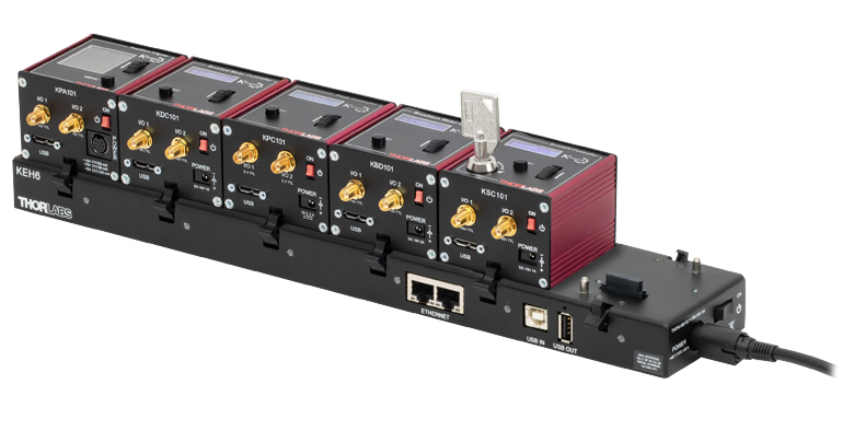 Click to Enlarge
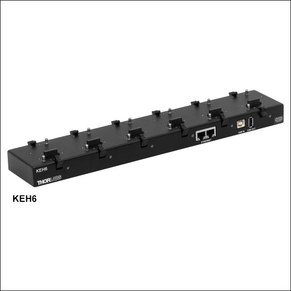
KEH6 Ethernet and USB Controller Hub
(Sold Separately) with Installed K-Cube® Modules
- Front Panel Velocity Wheel and Digital Display for Controlling Motorized Stages or Actuators
- Two Bidirectional Trigger Ports to Read or Control External Equipment
- Interfaces with Computer Using Included USB Cable
- Fully Compatible with Kinesis Software Package
- Compact Footprint: 60.0 mm x 60.0 mm x 49.2 mm (2.42" x 2.42" x 1.94")
- Power Supply Not Included (See Below)
Thorlabs' KDC101 K-Cube® Brushed DC Motor Controller provides local and computerized control of a single motor axis. It features a top-mounted control panel with a velocity wheel that supports four-speed bidirectional control with forward and reverse jogging as well as position presets. A backlit digital display is also included that can have the backlit dimmed or turned off using the top-panel menu options. The front of the unit contains two bidirectional trigger ports that can be used to read a 5 V external logic signal or output a 5 V logic signal to control external equipment. Each port can be independently configured.
The unit is fully compatible with our Kinesis software package. Please note that while the KDC101 controller is also fully supported by our XA software suite, the PY004Z9(/M) stage is not supported at this time, so the Kinesis software package should be used. A full list of products supported by XA can be found here. Please see the Kinesis Software tab for more information.
Please note that this controller does not ship with a power supply. Compatible power supplies are listed below. Additional information can be found on the main KDC101 DC Servo Motor Controller page.

 Zoom
Zoom
Click for Details
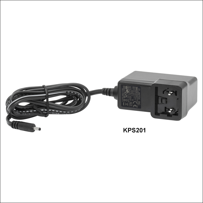
Figure 780B Each KPS201 power supply includes one region-specific adapter, which can be selected upon checkout.
Click to Enlarge
Figure 780A The KPS201 Power Supply Unit
- Individual Power Supply
- KPS201: For K-Cubes® or T-Cubes™ with 3.5 mm Jacks
- Ethernet and USB Controller Hub Provides Power and Communications
The KPS201 power supply outputs +15 VDC at up to 2.66 A and can power a single K-Cube or T-Cube with a 3.5 mm jack. It plugs into a standard wall outlet.
The KEH6 Controller Hub contains a fully compliant USB 2.0 hub circuit and provides all communications and power distribution for up to six K-Cubes, using only a single power connection. Additionally, the KEH6 hub has two Ethernet connection ports. The second Ethernet port or USB OUT port can be connected to the input on another Controller Hub to allow multiple Controller Hub connections while still only requiring a single Ethernet or USB cable from the host PC. The KEH6 hub draws a maximum current of 4.6 A; please verify that the cubes being used do not require a total current of more than 4.6 A.
For more information on the Controller Hub, see the full web presentation.

 Zoom
Zoom
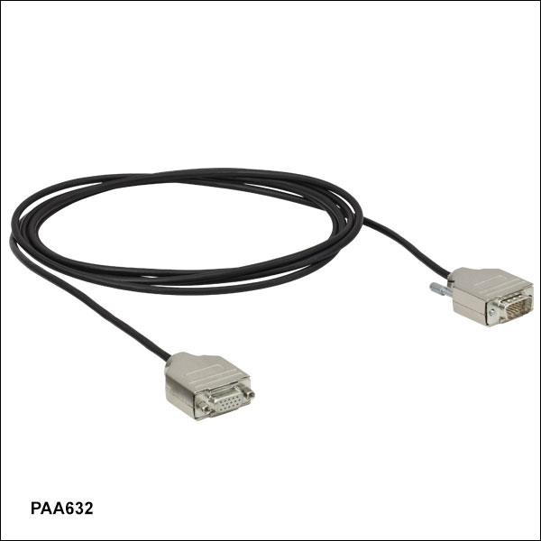
The PAA632 Extension Cable provides an additional 2.5 m (8.20 ft) of cable length for the 15-pin D-type connectors used throughout our motorized actuator selection. The male end connects to the controller, while the female end connects to the motor.