 Products Home / Active Optical Devices / Gain Chips / Tunable Laser Gain Chips with Thermoelectric Coolers
Tunable Laser Gain Chips with Thermoelectric Coolers
- Wavelength Ranges Centered at 1220, 1320, 1450, 1550, or 1900 nm
- Broadband Tunability
- Thermoelectrically Cooled Half-Butterfly Assembly
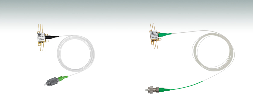
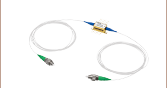
SAF1174S
CWL = 1320 nm,
SM Fiber
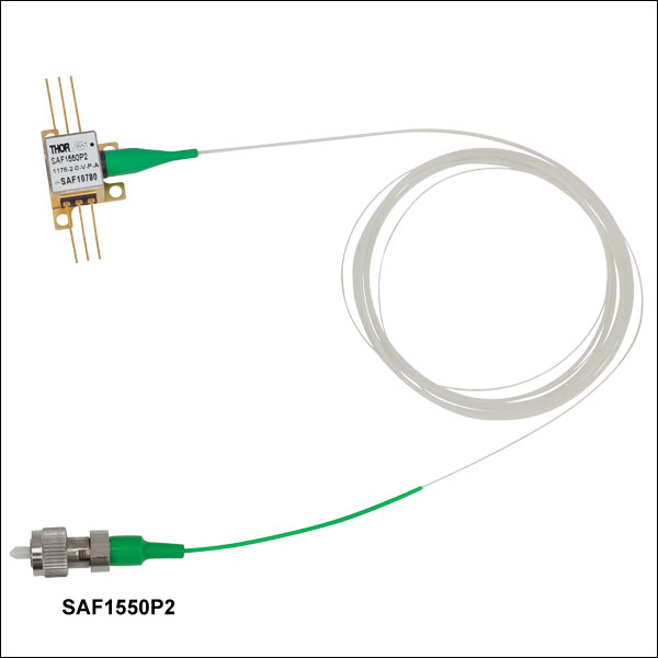
SAF1550P2
CWL = 1550 nm,
PM Fiber


Please Wait
| SAF Gain Chips |
|---|
| Chip in Ø9 mm TO Can |
| 780, 840, and 1040 nm CWL |
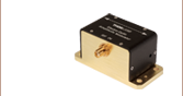
| Half-Butterfly Assembly |
| CWLs from 1220 nm to 1900 nm |
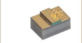
| Chip on Submount |
| 1220 nm CWL |
| 1320 nm CWL |
| 1450 nm CWL |
| 1528 - 1568 nm (C-Band) 1568 - 1608 nm (L-Band) |
| 1650 nm CWL |
| Webpage Features | |
|---|---|
| Clicking this info icon below will open a window that contains item specifications and graphs. | |
Features
- Gain Chips Mounted for Easy Integration into External Cavity Lasers
- Half-Butterfly Assembly with Thermoelectric Cooler
- AR Coating Eliminates Unwanted Reflections, Increasing Laser Stability, Output Power, and Spectral Quality
- 1.0 m Long (Min), SM or PM Tight Jacket Pigtail with FC/APC Connector
Thorlabs' family of Single-Angled-Facet (SAF) Gain Chips provides a gain medium for light in wavelength ranges centered at 1220, 1320, 1450, 1550, or 1900 nm. These gain chips feature AR coatings, an angled waveguide, and a proven SOA structure, which gives designers of external cavity lasers (ECLs) the highest power and widest tuning range available on the market. The gain chip is mounted in a half-butterfly package that collimates the output of the normal facet and couples it into an FC/APC connectorized fiber. A thermoelectric cooler (TEC) and thermistor, incorporated into the package and controlled with the easily accessible supplied pins (see the Graphs tab), enable tuning and optimization of the operating temperature.
On certain models, we can optionally provide a PM fiber or an optical isolator for the free-space input. Please contact Tech Support for a quote.
For more information on using a SAF gain chip in an external cavity laser, see the ECL Tutorial tab.
| This link opens a document that contains a comprehensive list of performance specifications and performance plots. |
All quoted values are typical, unless otherwise indicated. Please see the gain chip's Spec Sheet (linked below) for the most detailed information on performance. The Graphs tab describes the typical performace obtained in an external cavity laser configuration.
| General Specifications | ||||||||||
|---|---|---|---|---|---|---|---|---|---|---|
| Item # | Spec Sheet |
Reference Cavity | CWLa | Tuning Rangea, b |
Peak Powera |
Chip Gainc | Gain Ripple | R1 | R2 | Chip Length |
| SAF1175S | Littmann Cavityd | 1220 nm | 90 nm | 10 mW | 17 dB | 1 dB (Max) | 0.005% | 10%e | 1 mm | |
| SAF1174S | TLK-L1300Rf | 1310 nm | 100 nm | 70 mW | 35 dB | 1 dB (Max) | 0.005% | 10%e | 2 mm | |
| SAF1450S2 | TLK-L1450Rf | 1450 nm | 120 nm | 40 mW | 20 dB | 0.4 dB (Max) | 0.005% | 10%e | 1.5 mm | |
| SAF1550S2 | TLK-L1550Rf | 1550 nm | 120 nm | 40 mW | 17 dB | 0.6 dB (Max) | 0.005% | 10%e | 1 mm | |
| SAF1550P2 | TLK-L1550Rf | 1550 nm | 120 nm | 40 mW | 17 dB | 0.6 dB (Max) | 0.005% | 10%e | 1 mm | |
| SAF1900S | TLK-L1900Mf | 1900 nm | 170 nm | 7 mW | 18 dB | 1.5 dB (Max) | 0.005% | 20%e | 2 mm | |
| ASE Specifications | |||||
|---|---|---|---|---|---|
| Item # | Center Wavelength (Typ.) | 3 dB Bandwidth (Typ.) | ASE Current | Operating Current (Typ.) | Operating Current (Max) |
| SAF1175S | 1220 nm | 80 nm | 200 mA (Typ.) | 200 mA | - |
| SAF1174S | 1320 nm | 80 nm | 600 mA (Typ.) | 500 mA | 800 mA |
| SAF1450S2 | 1450 nm | 100 nm | 500 mA (Max) | - | 500 mA |
| SAF1550S2 | 1550 nm | 80 nm | 300 mA (Typ.) | 300 mA | 600 mA |
| SAF1550P2 | 1550 nm | 80 nm | 300 mA (Typ.) | 300 mA | 600 mA |
| SAF1900S | 1930 nm | 150 nm | 400 mA (Typ.) | 400 mA | - |
Note: The light polarization is horizontal inside the SAF Gain Chips.
*R2 = 10% for all models in the SAF series except the SAF1900S, for which R2 = 20%.
SAF Gain Chip Lasing Performance Using Littrow Tunable Laser Kit*
The innovative design of an SAF gain chip is ideal for use in external cavity lasers because it virtually eliminates unwanted feedback from the intracavity facet of the gain chip. These devices offer superior performance in a wide variety of external cavity configurations. Given below are typical spectra and details on the packaged devices.
*Our Littrow Tunable Laser Kit has been discontinued.
| Item # | Center Wavelength | Power vs. Current | Power Spectrum |
|---|---|---|---|
| SAF1175S | 1220 nm | ||
| SAF1174Sa | 1320 nm | ||
| SAF1450S2 | 1450 nm | ||
| SAF1550S2 | 1550 nm | ||
| SAF1550P2 | 1550 nm | ||
| SAF1900S | 1900 nm |
Basic Littrow Configuration
Fiber-Coupled SAF Gain Chip Drawing
External Cavity Diode (ECL) Lasers: Tunable Wavelength and Narrow Bandwidth
Two elements are required for a laser to operate: (1) an active gain medium that amplifies the optical signal and (2) a feedback mechanism to provide sustained laser oscillation. In a Fabry-Perot laser, two mirrors, having reflection coefficients of r1 and r2 (power reflectance R1 = r12 and R2 = r22), respectively, provide feedback for the optical field, as shown in Figure 41A.
Figure 41A Fabry-Perot Laser Structure
The round-trip gain for the optical field within a cavity of length L can be expressed as:
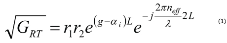
where g and αi are the gain and internal loss coefficients, respectively, λ is the vacuum wavelength, neff is the effective refractive index, and L is the cavity length. Solving for unity results in the threshold amplitude (Eq. 2) and phase (Eq. 3) conditions:
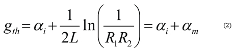
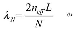
where αm is defined as the mirror loss and N is a running integer index representing the mode number.
In a semiconductor (diode) laser, the gain medium is excited by injecting a current into the junction region of a forward-biased diode. The high concentration of electrons and holes in the engineered quantum-well junction of a semiconductor laser makes it possible to create the population inversion required for optical gain.
When the gain medium is a semiconductor material, a Fabry-Perot cavity can be created by the Fresnel optical reflections at the cleaved facets of the chip. The junction is effectively a waveguide that extends from one facet to the other. An uncoated "as-cleaved" facet perpendicular to the waveguide has a reflectivity of R ~ 30%. However, the maximum output power of the device can be optimized by modifying the reflectance of the facets with optical coatings. Maximum power for a Fabry-Perot laser diode is typically achieved with a high-reflectivity (HR) coating on the back facet and a low-reflectivity (LR) coating on the front facet.
The emission spectrum of the Fabry-Perot laser diode device will be dependent on the injection current. When biased below threshold with g > αi , the emission spectrum consists of a broad series of peaks corresponding to the longitudinal modes of the Fabry-Perot cavity defined by the phase equation. Lasing does not occur until the injection current is increased to the point where g = αi + αm. The lasing wavelength is determined by the longitudinal mode that first achieves the threshold condition. The output spectrum does not always collapse into a single lasing wavelength but can consist of a narrow spectrum of longitudinal modes.
Figure 41B Gain Curve of a Fabry-Perot Laser
This is particularly true for InP-based Fabry-Perot lasers, which typically have an optical bandwidth of 5 to 10 nm. GaAs-based devices can operate in a single longitudinal mode, depending on wavelength and output power. They typically have an output bandwidth <2 nm.
A typical 850 nm laser diode with a length of around 300 µm and a group index around 4 will have a longitudinal mode spacing of 0.3 nm, which is similar to a 1 mm long 1550 nm laser diode. Changing the length or refractive index of the cavity, for example by heating or cooling the laser diode, will shift the whole comb of modes and consequently the output wavelength.
Laser Linewidth
The linewidth of a semiconductor laser single longitudinal lasing mode (FWHM) is given by the Schawlow-Townes-Henry Laser Linewidth equation, a modified Schawlow and Townes formula that incorporates the Henry linewidth enhancement factor αH [1]:
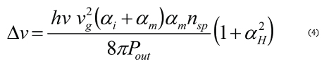
where hv is the photon energy, vg is the group velocity, nsp is the population inversion factor, and Pout is the single-facet output power. This equation describes the spectral broadening of the laser linewidth due to phase and amplitude fluctuations caused by the unavoidable addition of spontaneous emission photons to the coherent lasing mode. These so-called quantum noise fluctuations define a lower limit on the laser linewidth, which may be masked by larger noise fluctuations caused by mechanical/acoustic vibration or thermal variation.
Extending the length of the cavity will decrease αm (see Eq. 2), which reduces the linewidth. This can be understood by viewing the quantum noise-limited linewidth (see Eq. 4) as being proportional to the ratio of the number of spontaneous emission photons in the lasing mode. Increasing the cavity length both reduces the number of spontaneous emission photons (by decreasing the "cold-cavity" spectral width of each longitudinal mode) and increases the total number of photons in the cavity for a fixed output power. This is why the cavity length term appears twice in the Schallow-Townes equation.
A single-frequency distributed feedback (DFB) diode laser with cavity of 0.3 mm will typically have an emission linewidth on the order of 1 to 10 MHz. Increasing the length of the cavity to 3 cm, for example, will narrow the emission linewidth by a factor of more than 100. It has been shown [2] that the linewidth of the emission from an extended cavity semiconductor lasers can be reduced to <1 kHz.
Single Wavelength Operation and Tuning
For many applications, it is desirable to have a single longitudinal mode (single frequency) laser, to be able to adjust the lasing wavelength, or both. To accomplish this, a wavelength-selective feedback element external to the semiconductor laser chip can be used to select the lasing wavelength. Proper operation of this external cavity laser (ECL) requires suppression of the intrinsic optical feedback from the semiconductor chip Fabry-Perot cavity so that it does not interfere with the external feedback. The gain chip's Fabry-Perot cavity effect can be reduced by applying an antireflection (AR) optical coating to one chip facet.
Figure 41C External Cavity Operation Based on a Gain Chip
At a minimum, the chip facet reflectance (R1) should be 20 dB less than the external feedback (Rext); that is, R1 < 10-2 x Rext [3]. Even with the AR coating, the residual reflection from the AR-coated Fabry-Perot gain chip facet often limits the stability, output power, and spectral quality of the ECL, especially if the laser is tunable. To further reduce the reflection at the chip facet, the combination of an angled waveguide and an AR coating can be used to effectively remove most of the feedback from the internal chip Fabry-Perot cavity [4]. This single-angled-facet (SAF) gain chip provides a superior structure for ECLs, in particular broadband tunable ECLs.
Figure 41D Single-Angled-Facet Gain Chip
External Cavity Laser Design
There are numerous approaches for implementing an external cavity semiconductor laser [3]. The first consideration for most approaches is the choice of a wavelength-selective feedback element. One of the most common feedback elements is a diffraction grating, which can be used as the feedback element in both single-frequency and broadly tunable external cavity lasers.
When the collimated output of the gain chip is incident on a diffraction grating at angle θ with respect to the grating surface normal and perpendicular to the grating lines, the diffracted beams exit the grating at an angle θ' determined by the grating equation:
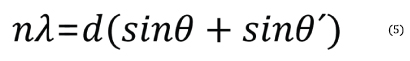
Here, n is the order of diffraction, λ is the diffracted wavelength, and d is the grating constant (the distance between grooves). For n > 0, the diffraction grating will spatially separate a polychromatic incident beam by diffracting the beam at an angle θ', which is wavelength dependent. Once the spectral content of the gain chip is spatially separated, a variety of means can be employed to selectively reflect light with a specific wavelength back into the gain medium.
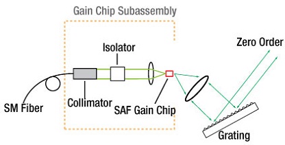
Littrow ECL Configuration
One of the simplest approaches is to use a Littrow configuration where the diffraction grating is oriented so that the first-order diffraction is retroreflected back into the gain chip (i.e., θ = θ' in Eq. 5):
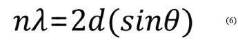
The laser output power can be taken from the zero-order reflection of the grating, which is often done because it minimizes the number of optical elements required to construct the ECL (a collimating lens and the diffraction grating).
Wavelength tuning is accomplished by rotating the diffraction grating, which varies the wavelength of light that is reflected back into the waveguide. When the diffraction grating (grating constant), collimation lens, and cavity length are chosen so that only one longitudinal mode is reflected back to the gain chip within the acceptance angle of the waveguide, the external cavity laser will produce a signle frequency laser spectrum. Note that the selection of collimation lens is important because it affects the amount of grating area that is illuminated as well as the focused spot size coupling back into the semiconductor gain chip. One of the disadvantages of this configuration is that the angle of the zero-order output beam changes as the wavelength is tuned. However, this problem can be avoided if the output of the ECL is emitted from the normal facet of the SAF gain chip. In this configuration, the reflectance of the SAF normal facet is typically reduced to R ~ 10% and a grating is chosen that efficiently diffracts light into the order being used to create the ECL to maximize the output power of the laser.
Figure 41E Littrow External Cavity Laser
Littman-Metcalf ECL Configuration
Another common ECL implementation is the Littman-Metcalf configuration, which uses an additional adjustable mirror to select the feedback wavelength [5]. The double-pass of the diffraction grating at an increased angle of incidence results in an external cavity that has better wavelength selectivity. As a result, the output beam of a Littman-Metcalf ECL typically as a narrower linewidth than a similar laser built using a Littrow configuration. In the Littman-Metcalf configuration, the output beam of the laser is typically the zero-order reflection from the diffraction grating, since the propagation direction remains fixed as the wavelength is tuned. In this case, the SAF normal facet is coated with a high-reflective (HR) coating, typically >90%, in order to minimize the losses in the ECL, which maximizes the output power.
Figure 41F Littman-Metcalf External Cavity Laser
For some applications it may still be desirable to use the normal facet of the SAF chip as the output coupler of the laser. For these applications, a low reflection coating on the normal facet of the SAF gain chip would be required in order to maximize the output power of the laser.
One drawback to the Littman-Metcalf design is that the internal losses are higher than in the Littrow configuration, and hence, the output power of the laser is typically lower. The increase in internal losses are mainly due to the loss of the zero-order beam reflected from the tuning mirror and the increased loss due to the decrease in the efficiency of the grating when used to reflect light at a large angle of incidence.
Innovative ECL Design
The innovative design of an SAF gain chip is ideal for use in external cavity lasers because it virtually eliminates the unwanted feedback from the intracavity facet of the gain chip. Thorlabs offers SAF chips with both low- and high-reflectivity coatings on the normal facet in order to support a wide variety of external cavity configurations. For information on custom coatings that optimize the performance of a particular external cavity laser configuration, please contact Tech Support.
References
(1) Henry, C. H., "Theory of the Linewidth of Semiconductor Lasers." IEEE J. of Quantum Electron QE-18, 259 (1982).
(2) Wyatt, R., Cameron, K. H., and Matthews, M. R. "Tunable Narrow Line External Cavity Lasers for Coherent Optical Communication Systems." Br. Telecom. Technol. J. 3, 5 (1985).
(3) Zorabedian, P. "Tunable External Cavity Semiconductor Lasers." Tunable Lasers Handbook Ed. Duarte, F. J. New York, Academic, 1995. Chapter 8.
(4) Heim, P. J. S., Fan, Z. F., Cho, S.-H., Nam, K., Dagenais, M., Johnson, F. G., and Leavitt, R. "Single-angled-facet Laser Diode for Widely Tunable External Cavity Semiconductor Lasers with High Spectral Purity." Electron. Lett. 33, 1387 (1997).
(5) Littman, M. G. and Metcalf, H. J. "Spectrally narrow pulsed dye laser without beam expander." Appl. Opt. 17, 2224 (1978).
| Posted Comments: | |
cdolbashian
(posted 2024-03-15 04:19:12.0) Thank you for your feedback. I am sorry that you feel this way about our product. I have contacted you directly to perhaps get some good comparisons within the industry, which we can aim to match. Oguzhan Kara
(posted 2023-03-20 13:22:59.88) Hi there,
We are interested in purchasing SAF1175S with PM fiber coupled version if possible. Would you mind if you advise availability such a gain chip with PM fiber (@1220nm)? Many thanks in advance.
Best regards,
Ozzy user
(posted 2023-03-01 17:09:48.047) Hi, I know this product is discontinued, but I am really interested in this tunable laser at 1220 nm, as there's nothing else at that wavelength on the market. Would it be possible to order this as a custom or one-off product still?
Thanks
Jeff ksosnowski
(posted 2023-03-02 11:39:42.0) Thanks for reaching out to Thorlabs. Unfortunately, we are no longer able to offer this kit or the laser used in it. I have reached out directly to discuss this further. Georgi Ynkov
(posted 2022-09-12 10:54:08.79) Hello,
What is the output light power of the (SAF1175S - Mounted SAF Gain Chip, Half Butterfly Pkg, CWL = 1220 nm, SM Fiber) and how does it change wavelength.
Best Regards
George
Georgi Yankov PhD ISSP BAS cdolbashian
(posted 2022-09-19 10:28:55.0) Thank you for reaching out to us with this feedback. All information regarding the power and wavelength distribution of the ASE can be found by clicking the blue "i" next to any of the products above. Attila Barocsi
(posted 2022-05-01 14:02:41.123) Please advice on how to operate the SKSAS
Spectroscopy Kit if the recommended TLK-L780M - Tunable Laser Kit, 770 nm is obsolete. Please suggest a reasonable alternative.
Regards,
Attila Barocsi jdelia
(posted 2022-05-11 04:47:19.0) Thank you for contacting Thorlabs. We unfortunately do not have a direct replacement to offer for TLK-L780M. I have reached out to you directly to discuss potential vendor recommendations. user
(posted 2021-04-15 16:07:32.21) What material six pins are made out of ? YLohia
(posted 2021-04-15 11:56:54.0) The pins are made of kovar and are plated with gold. Jin Ahn
(posted 2020-11-01 08:40:15.42) Hello, I am currently using TLK_L1550R in order to tune SAF1550S2 gain chip. However, I am currently having issue with setting 1st order diffraction maximum grating.
From the manual on page 11(step12), it mentions that 1st order diffraction maximum can be set up by rotating the
grating and locating its strongest diffraction with the
included IR viewing card.
But what does this visually mean on IR card? YLohia
(posted 2020-11-10 04:12:41.0) Hello, thank you for contacting Thorlabs. The strongest diffraction would be the beam that produces the brightest spot on the IR card. JIN Ahn
(posted 2020-06-10 00:51:53.45) Hi, I'm currently using ITC110 in order to control the TEC and laser current for SAF1550S2 gain chip.
However, I'm having some issue with the thermistor on the gain chip. From multi-meter, I get open line reading on gain chip thermistor. What could be the problem here? YLohia
(posted 2020-06-10 03:48:02.0) Hello, thank you for contacting Thorlabs. We are sorry to hear about the issues you are experiencing. This sort of issue usually occurs due to incorrectly wiring the thermistor connections to the temperature controller or a short somewhere in your temperature sensor. I have reached out to you directly to discuss this further. nick Yang
(posted 2020-05-26 22:03:26.033) Hi, I'm requesting inquiry in terms of operating SAF1550S2. We have noticed that the gain chip's TEC is operated with thermistor. We wanna know the thermistor specs in order to convert resistance value in terms of Celsius. Is there a way that we can get in touch with the thermistor spec sheets? YLohia
(posted 2020-05-27 09:27:30.0) Hello, thank you for contacting Thorlabs. These SAFs contain a 10 kOhm thermistor with the following Steinhart Coefficients:
A: 1.129241E-03;
B: 2.341077E-04;
C: 8.775468E-08;
The theoretical Beta value is 3870 at 25 C. guillaume.paradis
(posted 2018-08-01 12:12:19.907) Would it be possible to have the angled facet output be pigtailed? YLohia
(posted 2018-08-08 09:00:07.0) Hello, thank you for contacting Thorlabs. I will reach out to you directly about our custom capabilities. gksthf666
(posted 2017-04-24 11:50:33.363) To whom it may concern,
Greetings, I'm Hansol Jang and I'd like to get some customized SAF1550S2.
Can I get a SAF1550S2 without an integrated isolator?
An integrated isolator makes some problems in my research.
Also, can I select reflectances of both facet?
Best,
Hansol Jang tfrisch
(posted 2017-05-02 10:18:26.0) Hello, thank you for contacting Thorlabs. I will reach out to you directly about our custom capabilities. tcohen
(posted 2013-01-14 13:10:00.0) Response from Tim at Thorlabs: Thank you for contacting us! We are currently working on developing a 780nm SAF gain chip, fiber-coupled in a half-butterfly package. It would be feasible to incorporate an optical isolator at this wavelength in the half-butterfly package. We will contact you directly to keep you updated. jikim
(posted 2013-01-08 17:44:46.747) could you manufacture a TFP780A with a fiber output together with an optical isolator? The optical isolator has small priority, but the fiber output is required.
And could you produce a TFP780A with an angled facet at R1?
I look forward to hearing from you soon. Adam
(posted 2010-04-09 15:39:09.0) A response from Adam at Thorlabs: The fiber used in the SAF1176S is SMF-28. We will correct the drawing on the website so it references the correct part number. user
(posted 2010-04-09 14:56:57.0) The SAF1176S autocad drawing is reffering to a SAF1175 device(1220 nm) with a 1060 fiber. What fiber is used in the SAF1176S? |

 Zoom
Zoom- Designed for Use in a Littrow Cavity
- 1.0 m Long (Min), SM or PM Tight Jacket Pigtail with FC/APC Connector
Thorlabs' SAF Gain Chips are designed for use in wavelength ranges centered at 1220, 1320, 1450, 1550, or 1900 nm. The models designed for 1220, 1320, 1450, or 1550 nm (SAF1175S, SAF1174S, SAF1450S2, SAF1550S2, and SAF1550P2) feature an optical isolator on the fiber output, protecting the chip against back reflections and increasing laser stability.
Each SAF Gain Chip is individually burned in and rigorously tested to ensure long-term stability and compliance with our specifications. A complete test report will come with each serialized gain chip package.
Click the ![]() icon below for more detailed performance specifications.
icon below for more detailed performance specifications.
| Key Specifications | |||||||
|---|---|---|---|---|---|---|---|
| Item # | Info | ASE Center Wavelength |
ASE 3 dB Bandwidth |
ASE Current | Peak Gain | Gain Ripple | Operating Current (Typ./Max) |
| SAF1175S | 1220 nm | 80 nm | 200 mA | 17 dB | 0.5 dB | 200 mA/ - | |
| SAF1174S | 1320 nm | 80 nm | 600 mA | 35 dB | 0.35 dB | 500 mA/800 mA | |
| SAF1450S2 | 1450 nm | 100 nm | 500 mA (Max) | 20 dB | 0.4 dB (Max) | -/500 mA | |
| SAF1550S2 | 1550 nm | 80 nm | 300 mA | 17 dB | 0.6 dB (Max) | 300 mA/600 mA | |
| SAF1550P2 | 1550 nm | 80 nm | 300 mA | 17 dB | 0.6 dB (Max) | 300 mA/600 mA | |
| SAF1900S | 1930 nm | 150 nm | 400 mA | 18 dB | 1.5 dB | 500 mA/800 mA | |
 Click for Gain Chip Diagram