 Products Home / Fiber Components / Terminal Fiber Components / Faraday Mirrors with Fiber Optic Pigtail
Faraday Mirrors with Fiber Optic Pigtail
- Returns Light at 90° Orthogonal Polarization Relative to Input
- Bismuth Iron Garnet (BIG) Faraday Rotating Element
- 1310 nm and 1550 nm Design Wavelengths
- Unterminated, FC/PC, or FC/APC Versions Available
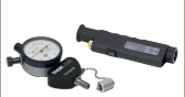
MFI-1310-APC
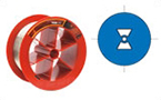
Faraday Rotator
(Magnet, Film)
Planar
Mirror
Lens
Internal Schematic


Please Wait
Click to Enlarge
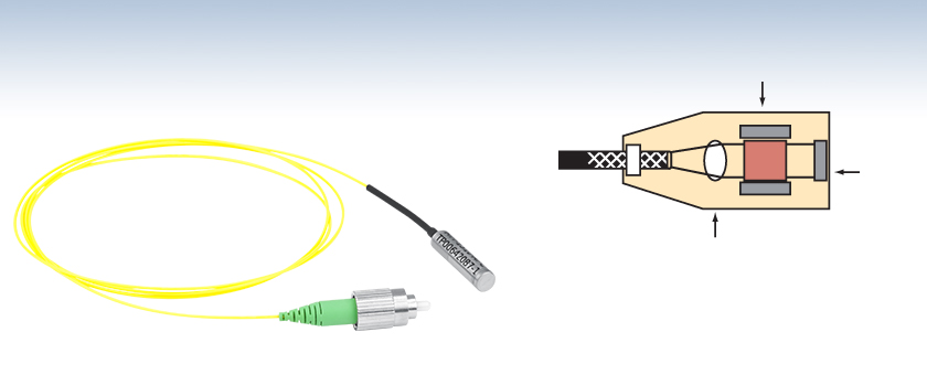
Figure 1.1 Schematic illustrating polarization rotation as light passes through the Faraday rotating element from the fiber input (top) and after reflecting off the mirror (bottom).
Features
- Returns Light with Polarization Rotated 90° Relative to Input
- Bismuth Iron Garnet (BIG) Faraday Rotating Element
- 1310 nm or 1550 nm Center Wavelengths Available
- Available with 2.0 mm Narrow Key FC/PC or FC/APC Connectors or Unterminated Leads
Thorlabs' Faraday Mirrors with a Fiber Optic Pigtail are designed to return light with a 90° orthogonal polarization relative to the input state of polarization (SOP). They allow for greater control over the design of systems such as fiber sensors, erbium-doped fiber amplifiers, and tunable fiber lasers. Faraday mirrors are available with center wavelengths of 1310 nm or 1550 nm. With <0.8 dB insertion loss and >50 dB return loss, these devices provide a high signal-to-noise ratio, which makes them ideal for use in fiber interferometers (see the Applications tab).
Rotation of the polarization state is achieved by passing light through a Faraday rotator (shown in Figure 1.1), which consists of a film of bismuth iron garnet (BIG) that has an external magnetic field applied to it by rare-earth magnets. A single pass through the Faraday rotator causes the polarization state of light to rotate by 45° ± 1°. A planar mirror placed after the Faraday rotator returns light back at the same angle of incidence; light passes through the Faraday rotator a second time and light re-entering the input fiber has a polarization state rotated 90°, or orthogonal, to the input polarization state.
Faraday mirrors additionally provide the ability to minimize alterations to the polarization state induced by thermal and mechanical perturbations in the fiber. This behavior is possible because the light will travel through the same fiber when entering and exiting the Faraday rotator (i.e., the pigtailed single mode fiber). Any perturbations to the polarization state that are caused by the fiber are reversed during the return trip. As such, Faraday rotator mirrors will correctly compensate for SOP changes caused by the fiber without using polarization-maintaining fiber; however, the return polarization will be orthogonal to the input polarization.
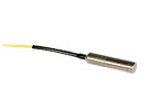
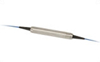
These Faraday Rotator Mirrors are pigtailed with 1 m of SMF-28 Ultra single mode fiber, which is mounted in a standard Ø900 µm tight tube buffer with proper strain relief. Versions are available with 2.0 mm narrow key FC/PC or FC/APC connectors; the 1550 nm Faraday rotator is also available unterminated.
Custom models are also available upon request. Contact Thorlabs' Tech Support for more information.
| Fiber Polarization Control Selection Guide | ||||||
|---|---|---|---|---|---|---|
| Polarization Controllers | Linear Polarizers | |||||
 |
 |
 |
 |
 |
 |
 |
| Motorized Fiber Polarization Controllers | Manual Paddle Fiber Polarization Controllers | In-Line Manual Fiber Polarization Controller | Free-Space FiberBench | Faraday Mirrors | In-Line Fiber Polarizers | Polarizing Fiber |

Click to Enlarge
Figure 2.1 Fiber-based interferometer using Faraday rotators to eliminate unwanted polarization effects.
Applications
Faraday rotators are useful for improving the performance of fiber interferometers, as well as fiber amplifiers and fiber lasers. When a Faraday rotator is placed at the end of a length of single mode fiber, any state of polarization (SOP) perturbations to the polarization state that are caused by the fiber are reversed during the return trip; however, the return polarization is rotated to be 90° orthogonal to the input polarization. This is especially useful in a fiber interferometer, where undesired changes in polarization must be controlled for successful interference. Figure 2.1 shows an example fiber interferometer setup which uses Faraday mirrors to neutralize undesired polarization effects.
Alternatively, as shown in Figure 2.2, when light passes through a length of fiber, such as an erbium-doped fiber amplifier, and is reflected by the Faraday mirror, the returning beam has a polarization direction orthogonal to that of the input beam. A polarizer can then be used to separate out the counterpropogating beams. This same principle can also be applied to a fiber laser, as shown in Figure 2.3.
Click to Enlarge
Figure 2.2 Fiber-based amplifier using a Faraday rotator to create an input and output beam with orthogonal SOPs.
Click to Enlarge
Figure 2.3 Fiber laser using a Faraday rotator to create an input and output beam with orthogonal SOPs.
| Posted Comments: | |
Ullrich Schwanke
(posted 2024-03-20 10:52:54.243) In the 'Applications' section of https://www.thorlabs.de/newgrouppage9.cfm?objectgroup_id=3365
the graphics
https://www.thorlabs.de/images/TabImages/Faraday_Mirror_App_D1-780.gif
appears to be inconsistent with the graphics
https://www.thorlabs.de/images/TabImages/FRM-Diagram-1_dwg_780.gif
that is shown when following the link 'Click to enlarge'.
Or am I missing something?
Thanks, Ulli user
(posted 2023-11-29 11:47:05.56) I see that you can make a Faraday mirror for 1064nm, would that extend down to 1013nm? cdolbashian
(posted 2023-12-15 09:21:23.0) Thank you for reaching out to us with this request! While we do not have this in our catalogue right now, I have suggested it to be a potential future release! Alternatively, perhaps we can do this as a custom. I have reached out to you requesting additional information which could facilitate such a custom. Héctor Álvarez Martínez
(posted 2023-01-13 11:48:00.04) To whom it may concern,
I bought a MFI-1550-APC and I would like to know its attenuation when used at 1396 nm instead of at 1550 nm +/- 8.5 nm. I can not see the specs.
When using it at the "wrong" wavelength, apart from the attenuation, any other precaution taht I should be worried about?
Many thanks in advance,
Héctor jgreschler
(posted 2023-01-17 09:58:21.0) Thank you for reaching out to Thorlabs. The published specs are only accurate for operation within the wavelength range of the device, for the 1550nm devices the bandwidth is 17nm. Custom wavelength configurations can be requested by contacting techsupport@thorlabs.com. Hao Tan
(posted 2022-09-23 22:48:55.773) I want to know how to test the rotation angle of a Faraday mirror. Jan Meyer
(posted 2019-07-18 07:56:02.72) Hello,
we bought a Faraday Mirror Subassembly from you, twice (meaning just the BIG Crystal and the magnet). We use this for experiments together with students. For a deeper understanding, could you please provide more detailed information about the BIG crystal itself and its magneto-optical characteristics, like an informative specsheet.
Regards
Jan YLohia
(posted 2019-07-18 12:42:55.0) Hello Jan, thank you for contacting Thorlabs. I'm reaching out to you directly to gather details on what information you require. yujun.deng
(posted 2014-09-24 17:18:04.853) I wonder whether you could have Faraday Mirrors with Fiber Optic Pigtail at 1064 nm. jlow
(posted 2014-09-25 03:32:37.0) Response from Jeremy at Thorlabs: We can build this. I will contact you directly to get the requirements for your application and quote this. Greg
(posted 2009-03-03 12:01:33.0) A response from Greg at Thorlabs to yfeng: Thank you for your interest in Thorlabs products. We are able to make custom Inline Faraday Rotator Mirrors. A member of our Technical Support team will be in contact with you shortly. yfeng
(posted 2009-03-03 06:50:48.0) Hi,
Do you offer Faraday rotator mirrors at 1180nm with similar specs?
Best Regards,
Yan Feng |
| Item # | Center Wavelength |
Bandwidth | Insertion Lossa,b |
Return Lossa,c |
Faraday Rotationa,d |
Max Power Level |
Fiber Pigtail | Termination |
|---|---|---|---|---|---|---|---|---|
| MFI-1310-FC | 1310 nm | 12 nm | 0.5 dB (Typ.) 0.8 dB (Max) |
>55 dB | 45° ± 1° | <300 mW | 1 m of SMF-28 Ultra | FC/PC |
| MFI-1310-APC | FC/APC |
| Item # | Center Wavelength |
Bandwidth | Insertion Lossa,b |
Return Lossa,c |
Faraday Rotationa,d |
Max Power Level |
Fiber Pigtail | Termination |
|---|---|---|---|---|---|---|---|---|
| MFI-1550 | 1550 nm | 17 nm | 0.5 dB (Typ.) 0.8 dB (Max) |
>55 dB | 45° ± 1° | <3 W | 1 m of SMF-28 Ultra | No Connectors |
| MFI-1550-FC | <300 mW | FC/PC | ||||||
| MFI-1550-APC | FC/APC |