 Products Home / Active Optical Devices / Electro-Optic Modulators / Free-Space Electro-Optic Modulators
Free-Space Electro-Optic Modulators
- High Performance Lithium Niobate Amplitude & Phase Modulators
- SMA RF Modulation Input Connector
- Broadband DC Coupled or High-Q Resonant
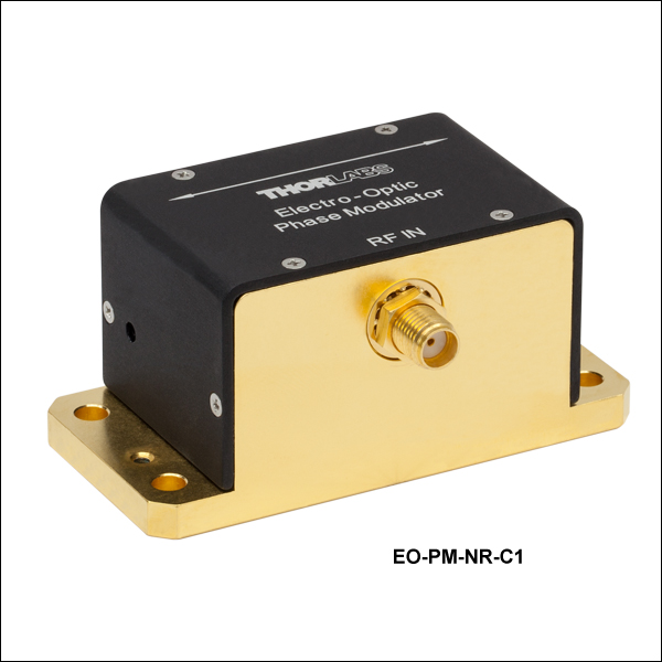
EO-PM-NR-C1
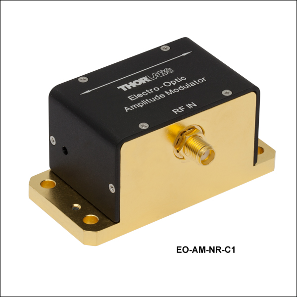
EO-AM-NR-C1
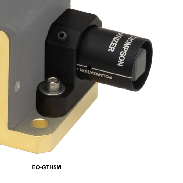
EO-GTH5M Application
EO-PMT
EO-GTH5M


Please Wait
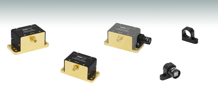
Lithium Niobate Electro-Optic Modulators
Thorlabs' free-space, lithium niobate, electro-optic (EO) modulators combine our expertise with crystal optics and high-speed electronics. Our EO modulators use MgO-doped lithium niobate to enable operation at higher power and shorter wavelengths. The modulators have an SMA RF input and are directly compatible with our HVA200 High-Voltage Amplifier (see Driver and Accessories). We offer both amplitude and phase modulators in non-resonant DC-coupled versions as well as high-Q, resonant, AC-coupled models, with anti-reflective coatings designed for a broad range of operating wavelengths.
Click to Enlarge
The required half-wave voltage needed to drive the EO modulators
is a function of the wavelength of the optical signal. The red and
blue lines correspond to the non-resonant EO Modulators while
the green line is for the resonant modulators. The half-wave voltage
shown for the resonant modulators is typical for the 20 MHz version.
Features
- High Performance in a Compact Package
- DC-Coupled, Non-Resonant or AC-Coupled, High-Q, Resonant
- 2 mm Diameter Clear Aperture
- Four Optical Bands: 400 - 600 nm, 600 - 900 nm, 900 - 1250 nm, and 1250 - 1650 nm
- MgO-Doped Lithium Niobate Crystals
- SMA RF Modulation Input Connector
- DC to 100 MHz Non-Resonant Bandwidth
- 20 MHz Standard Resonant Model
- Custom Resonant Frequencies from 0.1 - 100 MHz Available Upon Request
*Please note that modulators operating in the
400 - 600 nm range (C4 band) should only be used for AC modulation above a few Hz. MgO-doped lithium niobate can be sensitive to light in this wavelength range, displaying a slow negation to an applied DC field. The more intense the light, the faster the DC field is cancelled. Hence, in practice, a DC voltage cannot be used to bias the modulator at the desired operating point. Operation in the C4 band is also more sensitive to optical damage, so it is important to avoid excessive power density that can permanently damage the crystals.
DC-Coupled Non-Resonant Modulators
Our non-resonant EO modulators consist of EO crystals packaged in a rugged housing that is optimized for operation at any frequency from DC to
100 MHz. The user must supply an external high-voltage driver connected to the SMA RF input to achieve the desired modulation. The HVA200 driver can be used for frequencies up to 1 MHz. Please see the Specs tab for amplifier requirements. We offer amplitude and phase modulators with a
High-Q Resonant Modulators
Thorlabs' resonant EO Modulators operate at a much lower drive voltage, but at a fixed frequency using the built-in high-Q resonant circuit. Our standard resonant amplitude and phase modulators have a -C1 (600 - 900 nm) AR coating and operate at 20 MHz with a Q of about 15. Note that the Q at other, custom, resonant frequencies can be quite different. See the Graphs tab for more information on the coating reflectance. Standard and custom resonant frequencies are available from 0.1 to 100 MHz. Please contact
Driver and Accessories
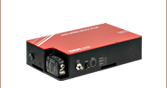
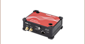
Driving these non-resonant, free-space modulators can sometimes be challenging because the load is almost purely capacitive. Our HVA200 high-voltage amplifier, which features a low-noise, ±200 V output and
1 MHz bandwidth, is designed for driving these non-resonant EO modulators up to certain limits. The 400 V output swing allows the HVA200 to fully modulate our non-resonant amplitude modulators for wavelengths up to ~1200 nm and our non-resonant phase modulators across all wavelengths. The HVA200 also provides an adjustable DC bias to allow for electrical biasing to the quadrature operating point of an amplitude modulator, and effectively utilize the ±200 V bipolar output swing to achieve full modulation.
For driving these same non-resonant modulators at frequencies higher than 1 MHz, or at longer wavelengths with higher voltage, specialized amplifiers with sufficient output power, linearity, and bandwidth to drive capacitive loads are required. These modulators do not behave like a standard 50 Ω load. Please contact Tech Support for more information.
The resonant modulators, on the other hand, have a resonant circuit that is tuned to be a 50 Ω load at the resonant frequency. This means they can be driven at lower voltages with standard frequency generators designed for 50 Ω impedance. Note that the generator must be tuned to the exact same frequency the modulator is designed for. Thorlabs can customize resonant modulators to operate at any frequency between 0.1 and 100 MHz. Please contact Tech Support for details.
Thorlabs also offers a Glan-Thompson Polarizer mounting adapter, as well as an EO modulator mount for integration into our FiberBench collimation hardware (see below).
Modulators
| Item # | EO Amplitude Modulator EO-AM-NR-Cx |
EO Phase Modulator EO-PM-NR-Cx |
EO Resonant Modulator EO-xM-R-C1 |
|
|---|---|---|---|---|
| Modulator Crystal | Lithium Niobate (LiNbO3) Doped with MgO | |||
| Wavelength Range | -C4 | 400 to 600 nma | 400 to 600 nm | N/Ab |
| -C1 | 600 to 900 nm | 600 to 900 nm | 600 to 900 nm | |
| -C2 | 900 to 1250 nm | 900 to 1250 nm | N/Ab | |
| -C3 | 1250 to 1650 nm | 1250 to 1650 nm | N/Ab | |
| Clear Aperture | 2 mm Diameter | 2 mm Diameter | 2 mm Diameter | |
| Input Connector | SMA Female | SMA Female | SMA Female | |
| Resonant Frequency Range | Broadband | Broadband | 20 MHzc | |
| Half Wave Voltage, Vπ (Click for Plot) | 205 V at 633 nm (Typical) (Click for Graph) |
136 V at 633 nm (Typical) (Click for Graph) |
15 V at 633 nmd (Typical) (Click for Graph) |
|
| Extinction Ratio | >10 dB | N/A | >10 dB | |
| Input Capacitance/Impedance | 14 pF | 14 pF | 50 Ohms | |
| Max RF Input Power | N/A | N/A | 3 W (35 Vpp) | |
| Max Optical Power Density | 2 W/mm2 @ 532 nm, 4 W/mm2 @ 1064 nm |
2 W/mm2 @ 532 nm, 4 W/mm2 @ 1064 nm |
2 W/mm2 @ 532 nm, 4 W/mm2 @ 1064 nm |
|
These plots show the reflectance of each of our four dielectric coatings for a typical coating run. The shaded region in each graph denotes the spectral range over which the coating is highly transmissive.

Introduction to Electro-Optic Modulators
- Introduction
- Static Phase Retardance (SPR)
- EO Phase Modulator
- EO Polarization Modulator
- EO Amplitude Modulator
- Effect of SPR in Amplitude Modulators
- Amplitude Modulator Compensation
- Compensation Methods
- Temperature-Independent Amplitude Modulator
- Operation in the Thorlabs Housing
- Driving EO Modulators
Click for Details
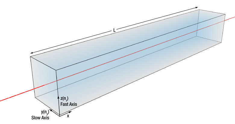
Figure 1: A schematic of a typical X-cut LN crystal used for EO modulators is displayed.
Introduction
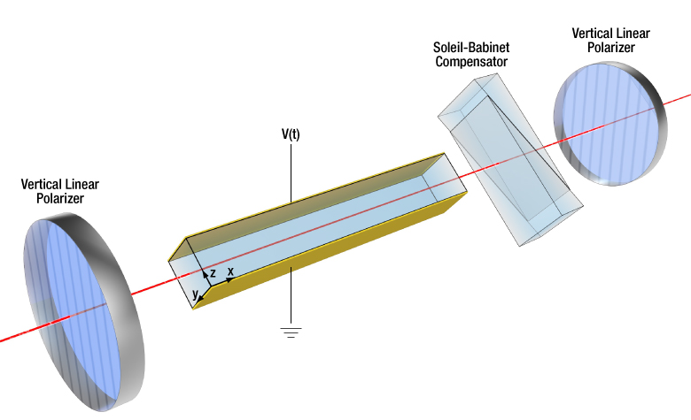
Thorlabs' free-space electro-optic (EO) modulators enable users to modulate free-space optical beams at speeds up to 100 MHz. They are based on MgO-doped lithium niobate (LN), which is known for its efficient EO response and utility over a broad range of wavelengths. LN is a birefringent, uniaxial EO crystal typically used in the geometry depicted in Figure 1. The crystal is cut, with respect to the crystalline axes, for optical propagation along the x-axis with a driving voltage applied across the z-axis. This gives the highest EO response for both phase and amplitude modulators. In the following text, we describe the basic principles involved and how they lead to use of this crystal in phase, polarization, and amplitude modulators.
The crucial aspect of this crystal geometry is that light is only allowed to propagate with two orthogonal linear polarizations along the crystal’s y-axis and z-axis. Since the crystal is birefringent, the two polarizations will experience different optical indices, ny and nz , and will therefore travel at different speeds. The difference between the indices, (ny - nz), is denoted by Δn. For LN, ny is greater than nz , so light polarized along the y-axis (slow axis) travels slower than along the z-axis (fast axis). As a result, when light enters the crystal the two orthogonal linear polarizations will travel at different speeds and exit the crystal with a phase difference corresponding to the optical path difference, which is Δn times the crystal length, L.
Static Phase Retardance (SPR)
The phase difference resulting from the crystal’s inherent Δn is commonly known as the static phase retardance, and is represented here as SPR. The SPR is a function of Δn, the wavelength, λ, and crystal length, L. The factor of 2pi gives the SPR in radians while the factor of 360, in the alternate equation, provides it in degrees.
SPR (radians) = 2pi ⋅ Δn ⋅ L / λ or SPR (degrees) = 360 ⋅ Δn ⋅ L / λ
Since LN is an electro-optic material, applying a voltage along the crystal’s z-axis electrically modulates ny and nz , such that Δn becomes a function of voltage, enabling phase and amplitude modulators. We will see that the SPR does not affect phase modulator operation but can have significant consequences in the operation of amplitude modulators. The SPR is subject to environmental influences and variations in the crystal and EO module manufacturing process. The SPR is therefore module specific and, for certain applications, must be determined and compensated for because it can range anywhere from 0 to 2pi.*
*Note: When we refer to the phase retardance of orthogonal polarizations exiting the crystal, this also includes the majority of cases where the crystal is long and the phase retardance can be many multiples of 2pi. However, for a single wavelength of operation, it is only the “net” phase retardance between 0 and 2pi that actually matters.

Click to Enlarge
Figure 2b: Modulated Output Phase Response of a PM
Click to Enlarge
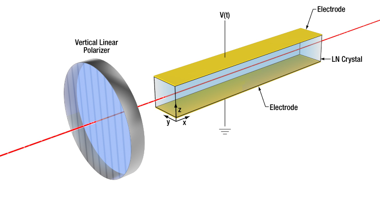
Figure 2a: Schematic of the Phase Modulator Configuration
EO Phase Modulator
The most efficient LN phase modulators (PMs) use input light that is vertically polarized along the same crystal axis as the applied voltage (z-axis), as shown in Figure 2a. Because the light is linearly polarized along only one of the principal birefringent axes, the SPR does not play a role, and the output polarization remains vertically polarized. In many applications, the absolute phase delay resulting from propagation at the output of the modulator is irrelevant. Only the modulated phase shift due to an applied voltage matters.
The applied modulation voltage, V(t), modulates nz , changing the optical path length and hence the phase shift of the output light. The half-wave voltage, known as Vpi, denotes the modulation voltage required to induce a pi (180°) phase shift. Figure 2b shows the voltage-induced phase shift due to the applied V(t). Here one can see that the resultant phase shift of the output light is linearly proportional to the applied voltage. The actual value of Vpi is a function of many factors (e.g. crystal dimensions and wavelength of light). For standard Thorlabs PMs, Vpi at 633 nm is about 150 V.
Click to Enlarge
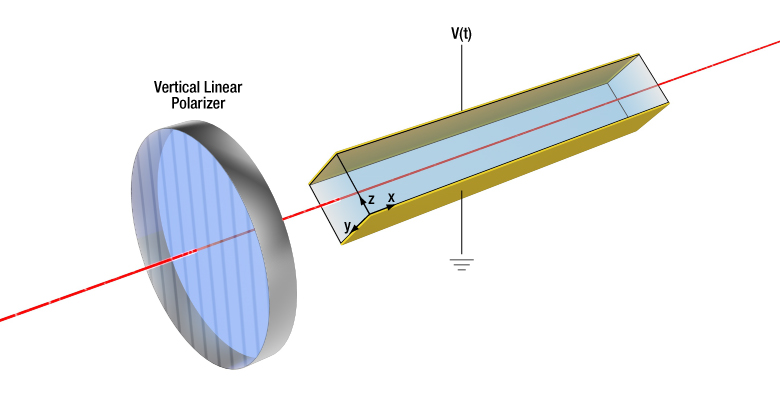
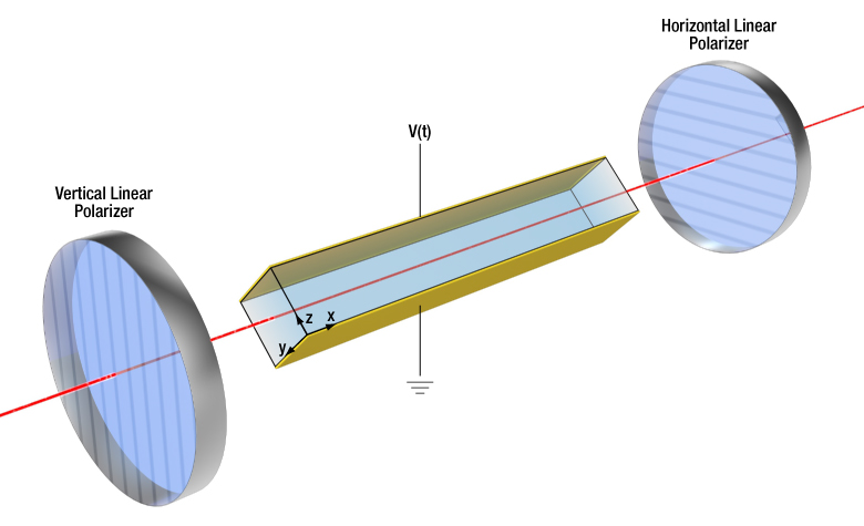
Figure 3: Schematic of the Polarization Modulator Configuration
EO Polarization Modulator
In an amplitude modulator (AM), the crystal is rotated 45° with respect to the modulator housing, while the input polarizer remains vertically oriented. Figure 3 illustrates this configuration. This results in the input light being equally split into two linear polarizations along the crystal y-axis and z-axis. These two components then develop a phase difference as they propagate through the crystal. This is the same principle as the SPR that was introduced earlier. We will now see that an applied voltage can introduce additional phase retardance, which we will call the voltage-induced phase retardance (VPR).
The applied voltage, V(t), changes the refractive indices along both the y-axis and z-axis, which introduces additional change to the phase retardance of the crystal. This additional voltage-induced phase retardance is called the VPR, which contributes to the total phase retardance (TPR) as given by:
TPR = SPR + VPR
It is the TPR that now determines the net phase retardance of the crystal. For example, in this case, when the TPR equals pi, the crystal behaves like a half-wave plate, resulting in a horizontal linear output polarization. A TPR of pi/2 would convert the linearly polarized input into a circularly polarized output, like a quarter-wave plate. Other phase differences yield various elliptical polarization states. In this way, the LN crystal rotated at 45° functions as a polarization modulator, as shown for a few standard cases in Figure 4.
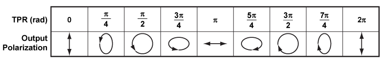
Click to Enlarge
Figure 4: Above is the relationship between the output polarization state and the total phase retardance imparted by the crystal, assuming the input polarization is vertical.

Click to Enlarge
Figure 5b: Ideal Amplitude Modulator Transmission Function with Parallel Polarizers

Click to Enlarge
Figure 5a: Schematic of the Amplitude Modulator Configuration with Parallel Polarizers

Click to Enlarge
Figure 6b: Ideal Amplitude Modulator Transmission Function with Crossed Polarizers
Click to Enlarge
Figure 6a: Schematic of the Amplitude Modulator Configuration with Crossed Polarizers
EO Amplitude Modulator
To create an amplitude modulator, a linear polarizer is placed at the crystal output to convert polarization change into amplitude change. Figure 5a depicts one configuration, where the second polarizer is oriented parallel to the first. The fraction of light transmitted through the output polarizer depends on the polarization of the light exiting the crystal. Only the polarization component aligned with the polarizer is transmitted. The transmission function, as shown in Figure 5b, is given by:
T = cos2(TPR/2)
where, as in the previous section, TPR = SPR + VPR.
For amplitude modulators, Vpi refers to the voltage required to induce a VPR of pi (or 180°). If the TPR = 0, then polarization does not change from input to output, and the output polarizer permits maximum transmission. When TPR = pi, the output polarization changes to horizontal, giving minimum transmission through the vertical polarizer. If the TPR is further adjusted to equal 2pi (or 360°), the transmission is once again maximized. It is important to note the cos2 transmission function is periodic, so the transmission is the same for all multiples of 2pi.
Note that if the output polarizer is changed to horizontal (or more generally, crossed relative to the input polarizer), as shown in Figure 6a, then the curve in Figure 5b would shift along the horizontal axis by pi. This results in the transmission function shown in Figure 6b, where maximum transmission is now at a TPR = pi.
Click to Enlarge
Figure 7: The above graph shows the effect of an arbitrary SPR on the voltage transmission response.
Effect of SPR in Amplitude Modulators
In practice, due to the unpredictable value of the SPR (which can be anything between 0 and 2pi), the transmission maximum likely does not occur at V = 0 V. SPR is a function of many factors like wavelength, temperature, and precise crystal dimensions. Out of the box, your EO modulator will probably have a nonzero SPR, meaning the transmission may take any value from 0 to 100% when V = 0 V (neglecting any losses from reflection and absorption).
The transmission curve in Figure 7 shows the effect of the SPR. For the sake of this example, we set the SPR at an arbitrary 0.7pi, but note that your modulator’s SPR can be anywhere between 0 and 2pi. In this example, the 0.7pi SPR sets the operating point (V = 0 V) transmission at ≈20%. Consequently, an applied voltage of Vpi would add an additional pi of VPR and thus give ≈80% relative transmission. Given the 0.7pi SPR in this example, you would have to add a voltage that induces an additional VPR of 0.3pi to reach the first transmission minimum. Or if you wanted to reach the maximum transmission, you would have to add a voltage that induces an additional 1.3pi of VPR.
Click to Enlarge
Figure 8: The above graph shows the effect of an arbitrary SPR on the voltage transmission response. CPR is added to SPR to set a new V = 0 V operating point.
Amplitude Modulator Compensation
The SPR results in an arbitrary transmission at 0 V, yet many applications require the modulator to be set at a specific transmission point like peak (T = 100%), quadrature (T = 50%), or null (T = 0%). In such cases, we must compensate for the SPR to reach the desired operating point. This is done by adding a compensating phase retardance, CPR. Methods for adding CPR are described in the next section. There are then three components to the TPR:
TPR = SPR + VPR + CPR
Figure 8 shows the transmission function and the same arbitrary, nonzero SPR used in the previous section. In this example, we add 0.8pi of compensation to reach the quadrature operating point (i.e., TPR = 3pi/2 and T = 50% at V = 0 V). Note you can add or subtract any value of compensation to reach any desired operating point.
It should also be noted that it is often possible to create custom versions of the modulator for specific wavelength applications that do not require an adjustable compensator. Please contact Thorlabs' Tech Support to discuss this.
Click to Enlarge
Figure 10: Amplitude Modulator Transmission Function at a Quadrature Operating Point
Click to Enlarge
Figure 9: Schematic of the Amplitude Modulator with Optical Compensation
Compensation Methods
If compensation is necessary to set a specific operating point for your application, then one of two main compensation methods can be employed: electrical or optical. The first method simply uses an applied DC voltage, VDC, in addition to the applied modulation voltage. In the example given in Figure 8, one must add a DC voltage of 0.8Vpi to reach the 50% transmission point. The equation for CPR then looks like this:
CPR = pi ⋅ VDC / Vpi = 0.8pi
The static DC voltage introduces an electrically tunable component to the CPR. This electrical DC compensation scheme works well at most wavelengths, but it’s worth noting that light at shorter wavelengths (400 - 600 nm) can actually produce an internal electric field that negates the applied DC electric fields.
The second method, optical compensation, however, works uniformly well at all wavelengths. For this we typically use a tunable waveplate, such as a Soleil-Babinet compensator. As shown in Figure 9, when aligned with the crystal's axes, the compensator introduces an optically tunable CPR. This is especially advantageous in the case of non-resonant amplitude modulators at long wavelengths, where extremely high voltages would be required for pure electrical compensation.
One of the benefits of optical compensation is that it can reduce the absolute voltage required for full modulation. In the AM example, setting the operating point at peak (T = 100%) or null (T = 0%) requires the full Vpi voltage to swing between a transmission minimum and a maximum. Alternatively, when the operating point is set to quadrature (T = 50%), the required voltage range becomes -Vpi/2 to +Vpi/2. This means the absolute value of the drive voltage is effectively cut in half, but it does need to be a bipolar source to allow both the addition and subtraction of VPR, as shown in Figure 10.

Click to Enlarge
Figure 11: Schematic of the Temperature-Compensated Amplitude Modulator with Optical Compensation
Temperature-Independent Amplitude Modulator
One of the tricky issues with LN modulators is that the crystal’s refractive indices are temperature-dependent due to the thermo-optic effect. To prevent the output polarization state from drifting with temperature, our amplitude modulators contain a second, matched crystal that is rotated by 90° with respect to the first. Figure 11 depicts this configuration. (Note: Thorlabs' PMs contain a single 40 mm long crystal, while AMs contain two 20 mm long crystals).
Each crystal independently contributes to the SPR, as given by:
TPR = SPR1 + SPR2 + VPR + CPR
where SPR1 and SPR2 are the static phase retardances introduced by the first and second crystals, respectively. Because the second crystal is rotated by 90°, its birefringent axes (y and z) are also rotated. Therefore, the SPR of the second crystal compensates for the SPR of the first. If the crystal lengths are perfectly matched, then SPR1 = -SPR2, and
TPR = VPR + CPR
In this way, the matched crystals compensate the thermal fluctuations in SPR, giving the modulator a temperature sensitivity below 0.01 rad/°C (in units of SPR per °Celsius). The matched crystals do not affect the modulation efficiency because they do not compensate the VPR, only the SPR. However, due to manufacturing constraints, there will still be some residual SPR. Even a small, μm-scale mismatch in crystal length can give an SPR anywhere from 0 to 2pi. Though the matched crystal pair gives effective thermal compensation, you will still need to use one of the compensation methods described in the previous section to set your operating point.

Click to Enlarge
Figure 12b: Orientation of the Polarizers with Respect to the EO Modulator Housing for an Amplitude Modulator
Click to Enlarge
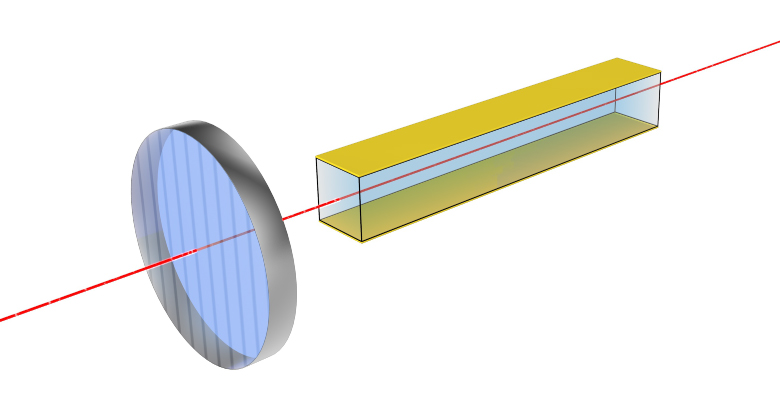
Figure 12a: Orientation of the Polarizer with Respect to the EO Modulator Housing for a Phase Modulator
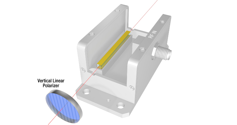
Operation in the Thorlabs Housing
Figures 12a and 12b show the orientation of the LN crystals and linear polarizers with respect to the modulator housing. The EO modulators contain only an LN crystal (two for amplitude modulators) and the electronic circuit to apply the external drive voltage. They do not contain the linear polarizers or optical compensator depicted in the previous sections. Phase modulators require only an input polarizer with vertical orientation (or a polarized laser source), while amplitude modulators require both input and output polarizers.
Figure 12a depicts the standard phase modulator (PM), while Figure 12b shows the configuration of the amplitude modulator (AM). The PM crystal is the same length as two AM crystals, so the half-wave voltages for either model are similar for a given wavelength. To be more precise, PMs always have a lower Vpi than the AM equivalent because the single polarization of the phase modulator sees a higher effective EO coefficient than the net EO coefficient between two orthogonal polarizations in the amplitude modulator.
Note that the input polarizer is not needed for either version of the modulator if the laser source is already vertically linear polarized. It is also possible to run these modulators with alternate polarization schemes, but that is beyond the scope of this document. Please contact Thorlabs' Tech Support for more information.
Driving EO Modulators
Driving free-space modulators can sometimes be challenging. Our HVA200 high-voltage amplifier, which features a low-noise, ±200 V output and 1 MHz bandwidth, is ideal for driving our broadband, non-resonant EO modulators when certain operating conditions are met. The 400 V output swing allows the HVA200 to fully modulate our non-resonant AMs for wavelengths up to ~1200 nm and our non-resonant PMs across all wavelengths. The HVA200 also provides an adjustable DC bias to allow for electrical compensation to the quadrature operating point of an amplitude modulator, and effectively utilize the ±200 V bipolar output swing.
For driving non-resonant modulators at frequencies higher than 1 MHz, or at longer wavelengths, specialized amplifiers with sufficient output power, linearity, and bandwidth are required. Additionally, for non-resonant modulators, the driver should be able to drive a purely capacitive load. These devices do not present with a standard 50 Ω input impedance.
Thorlabs also provides resonant modulators that have reduced input voltage requirements. These modulators (both AM and PM) come with an internal circuit that resonates at a specific frequency. This effectively multiplies the amplitude of the external sinusoidal drive signal to the higher voltage levels the EO crystals require. The trade-off is that these modulators only operate at a specific design frequency between 1 MHz and 100 MHz. Resonant modulators that operate at 20 MHz are available from stock, but other frequencies can be requested.
Please see the full web presentation for more details about resonant and non-resonant modulators, and contact Tech Support for any more specific information or custom requests.
| Posted Comments: | |
Yang Yang
(posted 2024-05-14 14:26:18.763) We recently bought a EO-PM-R-20-C1 for PDH lock. How can we increase the Q factor by modifying the mode-matching circuit to further reduce the half-wave drive voltage. ksosnowski
(posted 2024-05-16 04:32:43.0) Hello Yang, thanks for reaching out to Thorlabs. We hand-tune each of our high-Q resonators to the desired frequency, making a best effort to maximize Q. To drive to your desired modulation depth you may need to use an additional 50 Ω amplifier. Please contact Thorlabs Tech Support if you have concerns about driving your modulator. We have reached out directly to discuss your application in further detail. ksosnowski
(posted 2024-05-16 04:32:43.0) Hello Yang, thanks for reaching out to Thorlabs. We hand-tune each of our high-Q resonators to the desired frequency, making a best effort to maximize Q. To drive to your desired modulation depth you may need to use an additional 50 Ω amplifier. Please contact Thorlabs Tech Support if you have concerns about driving your modulator. We have reached out directly to discuss your application in further detail. user
(posted 2024-04-18 15:18:45.663) I would like to use the 400-600nm EOM EO-AM-NR-C4 for amplitude modulation at the full modulation rate of 100 MHz for a 10mW 405nm laser beam. Is this feasible? What is V_pi for this wavelength and EOM? ksosnowski
(posted 2024-04-26 09:50:08.0) Hello, thanks for reaching out to Thorlabs. The typical Vpi vs Wavelength can be found under the "Overview" tab above. For 405nm, this is close to 125V. The non-resonant models can be driven upwards of 1MHz however our HVA200 driver is only capable of driving the 14pF capacitive load up to 1MHz. We do also make resonant modulators up to 100MHz, which allow a much lower control voltage to drive the system, though the frequency performance is narrowband around the designed resonance. Operating EO-AM-NR-C4 at 100MHz would prove challenging as a very high current would be required to charge/discharge the capacitance in the 10ns period for this modulation, much higher than what our HVA200 can supply. A resonant amplifier model can help with this. I have reached out directly to discuss your application in further detail. Jeremie Margueritat
(posted 2024-03-27 21:51:42.913) I envisage to purchase teh EO-AM-NR-C4. However I read that in this range the AM modulators operating in the
-C4 band (400 - 600 nm) should only be used for AC modulation above a few Hz. I would like to work up to 500kHz in Amplitude modulation with 515 nm laser. Is the EO-AM-NR-C4 adapted for this use?
Best regards ksosnowski
(posted 2024-03-28 12:00:54.0) Hello Jeremie, thanks for reaching out to Thorlabs. You are correct that the -C4 version should only be used for AC modulation, any DC field will end up canceled by the applied light source. This means for any DC biasing of the modulator a physical waveplate should be used instead. On the other non-resonant modulator versions, a DC voltage can be applied to bias the retardance of the crystal. 500kHz is fine as it is well above the DC range of the device and is within the modulation range of our HVA200 driver as well. I have reached out directly to discuss this application in further detail. Seungeun Oh
(posted 2024-01-24 23:50:08.753) Which direction relative to the housing is the fast axis of the crystal in Resonant EO Modulators? Alexia RAVAILLE
(posted 2024-01-09 07:57:29.123) Dear Tech support team,
My question might seem stupid but I have a non resonant PM EO-PM-NR-C1 and I would like to know its input impedance. In the datasheet, it's specified that the resonant has 50 ohms of input impedance and the non resonant have 14pF capacitance but I can't find the info about the impedance of the non resonant. Does it mean that it's only capacitance with no impedance when non resonant ?
Also, how do we know if we have a resonant or a non resonant PM if we've lost the packaging of the component ?
Thank you and happy new year. ksosnowski
(posted 2024-01-10 02:47:40.0) Hello Alexia, thanks for reaching out to us. If the EOM is non-resonant, then you will be able to modulate the phase from DC to 100 MHz or so, as long as your driver can support it. If resonant, then modulation will only be possible near the resonance frequency (20MHz for our standard model). As long as you operate safely below the RF input maximum (3 W, 35 Vpp), you will not damage the resonant modulator. On resonance, the EOM will have a nearly 50 Ω impedance, whereas far from resonance it will have a highly reactive impedance, and will burn out if the 50 Ω resistance dissipates too much RF power. Since the non-resonant EOMs have a ~14 pF impedance (purely reactive aside from small parasitics) they do not dissipate power. This is why we don't spec a Maximum RF Input Power for the non-resonant modulators. Sebastian Eppelt
(posted 2023-10-05 10:17:12.85) Hello, we were planning to use a EO-PM-NR_C4 in our setup to surpress phase noise of one of our lasers. We have seen with home-built free-space EOMs that these can exhibit quite strong mechanical noise around ~1 MHz. Are there noise characteristics for the this model? Guangying Ma
(posted 2023-08-16 12:47:50.81) Hello,
I have bought the EO-PM-NR-C4. I am using a 488 nm (20 mW) laser as the input. Then I calculated the Vpi is 152.0 V. I applied a AC power, with -152 and 152 V, 1000 Hz square wave as the driving voltage. I found that the polarization of the input light was changed, however, the changed angle is very small, which is smaller than 15 degree. Could you help me to find what is the problem? Is the driving voltage I used is correct?
Thanks. ksosnowski
(posted 2023-08-29 05:48:04.0) Hello Guangying, thanks for contacting us. This is the correct Vpi however if the driver is not suitable it could struggle to switch the voltage fast enough resulting in effective peak voltage attenuation or if the input polarization alignment is incorrect this can result in a lack of dynamic range with the EO modulator. Our HVA200 driver is suitable for this application based on the amplitude, waveform, and total bandwidth. In case your laser system is unable to be rotated to change the input polarization, a halfwave plate can be used to effectively bias the input polarization angle before entering the EOM. I have reached out directly to discuss your application in further detail. Jihoon Kang
(posted 2023-04-21 11:47:07.397) Can you tell me the "maximum laser durability" (ex: 2.5 MW ...) of the modulator?
I also want to know about the "wavelength coverage". cdolbashian
(posted 2023-04-26 09:29:57.0) Thank you for contacting us Jihoon. All of this information (and more) is available above in the "Specs" tab. Additionally I would read through the document in the "Lab facts" tab as we have documented some testing with these devices. Cristian Tong
(posted 2023-01-01 02:37:58.223) Hello, I would like yo ask you about the insertion loss of the free space electro optic phase modulator EO-PM-NR-C1. This parameter is not specified in the specs of the device.
Thank you cdolbashian
(posted 2023-01-10 02:36:19.0) Thank you for contacting us Cris! If you are referring to the transmission vs reflection, we would expect ~.2% reflection over the AR coating range, and >98% transmission through the crystal (again, while operating within the AR coating range). I have reached out to you directly to discuss this inquiry. stefano chiodini
(posted 2022-09-09 10:20:53.787) Good morning, I have the following question.
For my project I need to use the C4-C1-C2-C3 EOM-AM of Thorlabs to cover a range from 400 nm to 1600 nm. The Vpi required voltages go from about 100 V to 600 V following your graph.
Since we could have troubles in covering the 300 V-600 V I was wondering if a phase EOM could be used... They have indeed lower Vpi voltages but I do not really understand the difference with the AM-EOM. Could you please help me out in this? Following your phase EOM description: "the value of n⊥ is not a factor". What does it mean? that only the parallel beam goes through?
Thank you,
Stefano Michael Lim
(posted 2022-07-19 11:40:28.22) Can this phase modulator be adapted for use at 2000nm? jgreschler
(posted 2022-07-22 04:21:26.0) Thank you for reaching out to Thorlabs. We do have custom wavelength capabilities for our EOM product line, you can request a quote by emailing techsupport@thorlabs.com. I have reached out to you directly with more information. Farooq Khaleel
(posted 2021-10-04 18:12:37.967) Dear Sir/Madam,
I hope that this message finds you well.
Please could you inform me about if these EO modulators supports bidirectional modulation? I mean could I apply the incident laser from the output port and extract the output from the input port? and vice versa?
In addition, what is the minimum detectable input power in Watt?
Thank you very much.
Yours sincerely, YLohia
(posted 2021-10-07 08:20:17.0) Hello, thank you for contacting Thorlabs. Yes, the modulators are bidirectional. These non-resonant modulators are a purely capacitive load- the power does not dissipate in the crystal. We do not specify an upper limit for how much power can be sent through the modulator. In these cases the driver is typically the limit on power, not the modulator. For our resonant modulators, e.g. EO-PM-R-20-1, the max RF power that can be sent through the device is 3W. If you are inquiring about the minimum optical input power, the modulators have no minimum input power (this is true for both the resonant and non-resonant models). The light is attenuated by a fixed amount depending on the applied voltage and the wavelength of the light. Think of it as a variable attenuating filter; it will absorb some percentage of the light regardless of how little power is put through it. The modulator is not the limit on how little power can be used in a system; it depends on how sensitive the detector is. T I
(posted 2021-09-24 12:11:21.52) Dear Thorlabs support team, I am using your free space LN modulators and need to know the exact crystal lengths. We could find some info in your previous replies to feedback comments, but it seems there is a conflict between the two responses below.
YLohia (posted 2019-11-12 11:18:13.0)
Our PM use only one LN crystal of 20mm length, as opposed to two orthogonal 20mm (adding up to 40mm) crystals used for AM
nbayconich (posted 2017-05-03 10:04:19.0)
The crystal length of our free space Amplitude modulators is 20mm. The LiNbO3 crystals in our free space phase modulators are 40mm in length.
Could you tell us the exact crystal lengths of the amplitude and phase modulators? YLohia
(posted 2021-10-08 03:03:04.0) Hello, thank you for your feedback. I seemed to have made a typo on my response posted on 2019-11-12 11:18:13.0 (which I have now corrected). The phase modulators only use one crystal of 40 mm length. The amplitude modulators use two orthogonal crystals, each 20 mm long, adding up to a total of 40 mm length. My sincere apologies for any confusion caused by the previous post. dongxu Bai
(posted 2021-06-01 16:45:52.517) 调制信号的频率范围是什么
What is the frequency range of the modulated signal YLohia
(posted 2021-06-04 02:48:43.0) These modulators can be used from DC to 100 MHz. user
(posted 2021-05-24 18:52:46.0) Hi, could you tell me the price of the customized resonant EOM? Thanks. YLohia
(posted 2021-05-27 02:39:22.0) Hello, custom items are quoted by emailing your local Thorlabs Tech Support team (in your case, techsupport.uk@thorlabs.com). We will discuss the pricing directly. Michal Pawlak
(posted 2020-10-24 02:46:00.01) Dear Sir Madam
could you please explain my problem.When I will buy your EO amplitude modulator with driver I can modulate between DC 100 MHz. Or frequency is limit to 1 MHz as is stated in description of driver.
best wishes
Michal YLohia
(posted 2020-10-26 09:34:30.0) Hello Michal, thank you for contacting Thorlabs. The EOM itself is capable of modulating up to 100 MHz but the HVA200 limits that capability to 1 MHz. Haechan An
(posted 2020-10-18 18:53:46.15) Hi, I want to create sidebands at 780 nm using EO-PM-NR-C1 with a modulation frequency of around 20 MHz. But it turned out that we need high voltage to see those sidebands easily. (Probably need a voltage higher than 50 V but we only can go up to 10 V right now.) Can you tell me the equivalent electric circuit of EOM so I can build a resonant RLC circuit using resonators and inductors? Or is it enough to assume the EOM as a 14 pF capacitor? YLohia
(posted 2020-10-23 03:34:35.0) Hello, thank you for contacting Thorlabs. The modulator can be modelled purely as a 14pF capacitor. The exact capacitance is given on the serialized test sheet that ships with each unit. user
(posted 2020-10-19 16:59:00.947) 我想要用这个电光调制器实现633nm激光的偏振调制,请问能够实现吗?请问电光调制器配置有偏振片吗? YLohia
(posted 2020-10-19 03:12:46.0) An applications engineer from our team in China (techsupport-cn@thorlabs.com) will reach out to you directly. 宝利 刘
(posted 2020-06-15 08:20:11.92) 我想利用这个EOM调制f=76MHz脉冲激光,调制频率为f/4,即2个脉冲透过,2个脉冲不透过。这个调制频率f/4由激光器的频率锁定。这种可以定制吗? YLohia
(posted 2020-06-15 09:53:28.0) Thank you for contacting Thorlabs. An Applications Engineer from our Tech Support team in China will reach out to you directly. Caroline Muellenbroich
(posted 2019-11-12 09:43:11.917) Hi Thorlabs team,
I am trying to modulate the power of a pulsed 1300nm laser with a EO-PM-NR-C3 using a voltage amplifier that has an output of +/- 150V.
The half wave voltage for my wavelength is 300V which I cannot supply. Am I right in thinking that by supplying 150V, and using a quarter waveplate before the input, that is inputting ciruclarly polarised light into the EOM, I should be able, with a Glan Thompson at the output of the EOM, to modulate the output power of my laser? Many thanks. YLohia
(posted 2019-11-12 11:18:13.0) Hello Caroline, thank you for contacting Thorlabs. Your understanding is correct regarding the use of the waveplate. By using a quarter waveplate on the input, you can cut down the V_pi in half. We have more information regarding this technique in the "Lab Facts" tab of this page. That being said, we do not recommend attempting amplitude modulation with a phase modulator.
While PMs can be used as AMs with additional polarization optics, they will not make good amplitude modulators. Our PM use only one LN crystal of 40mm length, as opposed to two orthogonal 20mm (adding up to 40mm) crystals used for AM, that eliminates static birefringence. These crystals exhibit thermal birefringence, which means that a phase modulator will have thermal drift issues when used as an amplitude modulator. One good question would be why phase modulators exist since amplitude modulators would do exactly the same thing while offering better performance due to the lack of thermal issues. The reason is that thermal effects are relatively insignificant for PM due to the input beam being polarized along one of the crystal axes. This thermal drift produces a DC phase shift (equivalent to adding few um of OPL). Our phase modulators are made with MgO-doped lithium niobate crystals. This material works well for phase modulation, and the MgO doping helps to increase the material's resistance to photorefractive damage. However, one drawback to this material is that it exhibits increased wavefront distortion (as opposed to undoped lithium niobate). For most phase modulation applications, wavefront distortion of the optical beam does not present any problems (can cause problems when being used for interferometry resulting in poor phase contrast), but when used as an amplitude modulator, the wavefront distortion causes poor extinction ratios. kar-hooi_kuan
(posted 2019-02-20 06:15:13.65) Hi,
I'm interested in Amplitude Modulations EO Modulators. I would like check with you if the optical input can be connectorized with FC/APC connectors? I will need it to be connectorized. If it can be connectorized, could you please quote me together with the EO MOdulator High Voltage driver?
By the way, what is the maximum modulation frequency supported by this EO-PM-NR-C3?
Thanks a lot. YLohia
(posted 2019-02-21 08:48:45.0) Hello, thank you for contacting Thorlabs. Unfortunately, this cannot be connectorized as it requires a collimated free space beam in order to work properly. What wavelength are you hoping to use this for? If it's around the 1550nm range, I would recommend looking into our fiber coupled LN modulators here : https://www.thorlabs.com/newgrouppage9.cfm?objectgroup_id=3918. These can go up to 10 GHz, whereas the model you were interested in is suitable up to only 100 MHz.
Another option would be using a FiberBench of at least 70mm length with two Fiberports to make the free space EOMs fiber-compatible. Please see the bottom of this page for more information. zenin
(posted 2019-02-20 10:42:19.48) Hi,
I am investigating the project of building fast noise eater (faster than 1 MHz) for my free-space lasers by using your EO modulators. I am wondering, can you make EO modulator witohut anti-reflection coating? It is because I have several sources from in VIS and NIR ranges (600-1800 nm). Also I am wondering, can Thorlabs make such noise eater, and if yes, how much will it cost? Looking forward to your reply.
Best,
Vladimir YLohia
(posted 2019-02-21 09:02:09.0) Hello Vladimir, thank you for contacting Thorlabs. Quotes for custom modulators can be requesting by emailing your local Thorlabs Tech Support group (techsupport.se@thorlabs.com in your case). We will reach out to you directly to discuss the possibility of offering uncoated crystals.
That being said, please note that the total transmission will suffer greatly when using uncoated crystals. The amplitude modulators consist of two lithium niobate crystals, which means that the reflectivity will be quite high from a total of four surfaces since the optical index is about 2.3. When this happens, you can get multiple reflections within the crystal that see different amounts of modulation and can interfere with each other. The workaround for this would be to tilt the crystal as far as possible and then prevent the reflected beams from getting in the system by clipping them with an aperture or edge of some kind.
Unfortunately, we are unable to offer a fully designed 1 MHz noise eater at the moment, though it is something that I will suggest on our internal engineering forum. vinx-d
(posted 2019-01-17 04:35:15.51) I am going to use the HVA200 in order to amplify a input voltage. I was wondering if I can amplify the bias without using any input. YLohia
(posted 2019-04-01 04:43:39.0) Hello, thank you for contacting Thorlabs. I reached out to you at the time of the original post in order to gather more information about your request. Please send us an email at techsupport@thorlabs.com if you did not receive our email. kkss0330
(posted 2018-10-11 00:29:20.047) Hello, I bought EOM that model number of EO-AM-NR-C4, I will operate laser source wavelength 633nm. I know that this supports a wavelength band from 400 to 600nm, can EOM work well from 633nm? YLohia
(posted 2018-10-11 09:53:27.0) Hello, thank you for contacting Thorlabs. The -C4 coating typically has a reflectivity of around 0.5-0.7% at 633nm. Since you already have the EOM with you, we recommend that you test it out yourself to see if the change in performance fits your requirements. baudin
(posted 2018-03-27 16:27:15.35) Hello, the specs say the load impedance is 14 pF, can you provide the loss angle function of frequency? YLohia
(posted 2018-04-03 10:26:35.0) Response from Yashasvi at Thorlabs USA: Hello, thank you for contacting Thorlabs. While we don't have a loss angle as a function of frequency spec at the moment, we do have a spec for the loss tangent @ 400 °C:
x-axis: tan(δ) = 0.0006
y-axis: tan(δ) = 0.001
We have seen values around ~0.003 for the loss tangent at 1 GHz. This is a property of the material (lithium niobate) itself. parksj003
(posted 2018-01-28 22:03:42.99) I am going to use a HVA200 with EO-AM-NR-C1 for fast light intesnity modulation (on/off).
I am wondering the rise/falling time of HVA200 and the time dealy between input and output. nbayconich
(posted 2018-02-23 10:49:58.0) Thank you for contacting Thorlabs. The typical rise/fall time of the HVA200 alone is about 350ns at 1Mhz, however the HVA200 is typically limited to the slew rate which is 400V/µs. We have not yet tested time delay when using an intensity EO modulator with the HVA200 at the moment. tanmaybhwmk3
(posted 2017-11-15 01:51:46.267) Hi. What is the expected insertion loss of the EO-AM? tfrisch
(posted 2017-11-20 05:18:05.0) Hello, thank you for contacting Thorlabs. The loss through the modulator is <1dB, typically about 0.5dB. fyk15isy
(posted 2017-10-02 15:09:40.037) Hi! I am looking for an EOM to do an amplitude modulation of 880 nm beam from OPO with an average power of 1 W. (It actually produces 5 ps pulses with 80 MHz repetition rate). I plan to focus the beam into the EOM since my beam diameter is too large for this EOM. Will this EOM be able to withstand this power when using short focal length lenses (50 - 100 mm lenses)? tfrisch
(posted 2017-11-14 02:48:07.0) Hello, thank you for contacting Thorlabs. These EOMs are intended to be used with a collimated input. If there is significant convergence or divergence, this would give an angular dependence on the optical path length which would affect the retardance and therefore amplitude modulation. I will reach out to you directly about damage and other methods of limiting the beam diameter. user
(posted 2017-05-02 11:05:15.013) What's the LiNbO3 crystal length of EO-AM-NR-C1? 20 mm? nbayconich
(posted 2017-05-03 10:04:19.0) Thank you for contacting Thorlabs. The crystal length of our free space Amplitude modulators is 20mm. The LiNbO3 crystals in our free space phase modulators are 40mm in length. A tech support representative will contact you directly. melanie.lebental
(posted 2017-02-06 09:19:47.293) Hello,
Please, what is the maximal speed of modulation from 0 to Vpi for the wavelength 532 nm ? 100 kHz ? 1 MHz ?
Best regards, tfrisch
(posted 2017-02-14 02:10:19.0) Hello, thank you for contacting Thorlabs. The maximum frequency will depend on the max current that can be supplied by the voltage driver, and the function of that signal. In the case of a sine wave, the maximum frequency is Imax/(pi*Vpp*C) where Imax is the max current of the driver, Vpp is the peak to peak voltage of the signal, and C is the capacitance of a non-resonant modulator (14pF for our units). I have contacted you with information on this derivation. parksj003
(posted 2016-12-01 16:27:36.453) Hello,
I am looking for fast polarization modulator.
The sorce we are using is femto-seond laser (wavelength ranging from 700-1000 nm, Power ~3W, beam diameter ~1.5mm). I think EO-AM-NR-C1 might be fine, as it can fastly alternate the laser beam polarization (but I am not sure yet). We need to alternate the beam polarization either vertically or horizontally (with a speed of at least 5 kHz). Would you let me know if there is proper solution for us?
Best,
Seongjun tfrisch
(posted 2016-12-01 08:41:41.0) Hello, thank you for contacting Thorlabs. I'd like to ask a few questions about your laser, so I will contact you directly about that. As for changing the polarization state, in general, that is how these freespace amplitude modulators work, you would just not use an output polarizer to drop the intensity for the state crossed to the input state. If your input is vertical, then a voltage of Vpi would give horizonatally polarized light. The fast axis of the crystal is at 45 degrees with respect to the housing, so you may use horizontal or vertical input. gksthf666
(posted 2016-11-22 05:18:04.04) To whom it may concern,
Hi, I'm Hansol Jang and I need some resonant type amplitude modulator with following properties.
1. Resonant frequency : 80 MHz
2. AR coating : 600 - 900 nm (actually, I need 750 to 1000 nm range)
3. Polarization : Schematic diagrams shown in website are pretty confused.. Which one is correct? (single crystal with linear polarizer or dual crystals) It is suitable for my system that input and output polarization is vertically or horizontally changed with respect to base (bottom) of EOM module.
Best,
Hansol Jang tfrisch
(posted 2016-11-22 07:32:36.0) Hello, thank you for contacting Thorlabs. For your first two notes, we can provide a quote for you. As for the polarization, the free space amplitude modulators use two LiNbO3 crystals which have their fast axes offset to mitigate changes in birefringence due to thermal effects. These are mounted at +45 degrees and -45 degrees with respect to the housing, so for the best extinction, the input polarization state should be vertical or horizontal. The EOM introduces an ellipticity to the polarization state, so an output polarizer will cause the change of amplitude. This output polarizer can be either parallel to or crossed to the input polarization (horizontal or vertical). jchg2758
(posted 2016-08-29 12:33:53.187) Hello, Recently I used the eo phase modulator for generating 2 MHz sidebands on 80 MHz rep. rate frequency comb. A RF signal generator makes 20 dBm 2 MHz signal and your company's 200 V amplifier makes additional bias and amplification. However there is only -70~-80 dBm sidebands and it hard to find the decreasing of fundamental. I set the vertical pol. input and enough optical power. Is there any mistake about choosing product? align miss? lack of amplification? I'm look forward to your answer. Thanks. tfrisch
(posted 2016-09-01 11:47:51.0) Hello, thank you for contacting Thorlabs. The relative intensity of sidebands will be dependent on the modulation depth of the phase. The relation between voltage depth and phase modulation depth is wavelength dependent. I will contact you directly about your application. killian
(posted 2016-08-03 11:14:04.56) Hello, I am looking for an EOM to use as a phase modulator for both 532 nm and 1064 nm light. The beams are CW, co-propagating.
I would need an AR coating that covers both wavelengths because I don't want much loss passing through the EOM. Can you provide a specialty coating?
The biggest requirement though is the variation in the half-wave voltage with wavelength. I need a controllable, differential phase shift of the 532 and 1064 nm light. In other words, I need a material for which the half-wave voltage deviates as much as possible from being linear with wavelength. I want to be able apply a voltage and shift the 1064 one wavelength while shifting the 532, for example, 2.5 wavelengths instead of two. It doesn't have to be exactly that, but I need the differential control of the relative phases.
The provided curves for Lithium Niobate look promising. If I can apply up to about 1000V, I can shift the 1064 phase 2 wavelengths, while shifting the 532 4.5 wavelengths, which would be just enough for my application. What is the peak DC voltage that can be applied to your phase modulators?
Thanks,
Tom gkatsop
(posted 2016-02-05 18:27:12.06) Hi. We are interested in modulating the polarization of a 1315nm laser (from right-circular to left-circular polarization and back) at a frequency of a few kHz, using your EO-AM-NR-C3. However we notice that your HVA200 amplifier provides a +/-200V output, whereas the half-wave voltage at 1315nm is around 450V. Supposedly then, the HVA200 is of no use for us and we would have to search for another amplifier, correct? Is there something you could propose in this direction? Is this EOM otherwise ok with our application? Kind regards, George. besembeson
(posted 2016-02-10 12:47:22.0) Response from Bweh at Thorlabs USA: With a suitable driver and a quarter waveplate in a rotation mount at the input, and a linear polarizer and quarter waveplate at the output, you should be able to achieve this. We will contact you with suggestions for high voltage amplifiers. peh
(posted 2015-10-22 17:53:25.073) Is it possible to use a modulation signal with the following properties together with the HVA200 and E=-AM-NR-C4?
repetition period 100 µs
High signal time 1 µs besembeson
(posted 2015-10-28 11:16:54.0) Response from Bweh at Thorlabs USA: The slew rate for the HVA200 is 400V/us. If you require up to V_pi, for the EO-AM-NR-C4, you will need about 200V maximum (at 600nm for example), which will take about 0.5us at best from the HVA200 so you will end up with an almost triangular waveform, instead of a 1us/100us square wave. The shape of the waveform will vary depending on your wavelength and voltage requirement. If the 1us (High signal) excludes the voltage ramp up time, then this could be suitable. cweidner0
(posted 2015-02-10 11:35:56.063) Is this EOM suitable for use in interferometric applications? Is there significant wavefront distortion as the laser passes through the crystal? Has this distortion been quantified in any way? besembeson
(posted 2015-02-12 12:05:11.0) Response from Bweh at Thorlabs USA: We don't have data yet quantifying the transmitted wavefront error for these devices. I will followup by email to discuss your application further. user
(posted 2014-10-29 12:56:55.817) Wondered if HVA200 includes a BNC cable? It would be better for us to know on a webpage if there is chart telling us what are included. jlow
(posted 2014-10-30 01:46:14.0) Response from Jeremy at Thorlabs: Thank you very much for your feedback. The HVA200 includes a BNC to SMA cable. We will look into adding this on the website. aklossek
(posted 2014-10-22 14:09:33.31) Dear ladies and gentlemen,
please tell me the total geometrical length of the lithiumniobat crystals within the EO-AM-R-20.
I need this to compensate the delay caused by this optic.
Best regards
André Klossek jlow
(posted 2014-10-22 01:53:19.0) Response from Jeremy at Thorlabs: The amplitude modulator has two crystals and each one is 20mm long. aklossek
(posted 2014-10-16 10:16:47.867) Dear ladies and gentlemen,
I am interested in your EO-AM-R-20-C1.
My question is about the temperature stability. Does the EOM need some specified, stable climate conditions (temperature)?
Best regards
André Klossek jlow
(posted 2014-10-22 03:57:46.0) Response from Jeremy at Thorlabs: The amplitude modulators are made with 2 crystals oriented 90° from each other. This configuration greatly reduces the temperature sensitivity so you can use this in a regular lab environment. I will contact you directly to discuss about this further. h.schultheiss
(posted 2013-10-17 16:12:25.66) Hello,
I plan on using one of your modulators for the generation of sidebands with a frequency separation from 1 GHz to 20 GHz. I used already your phase modulator for this purposes and it works for a couple of frequencies, but now want to build a new setup and I was wondering, if I could use the amplitude modulator as well. What is actually the difference between the amplitude and the phase modulator, the price is the same.
Best wishes,
Helmut Schultheiß jlow
(posted 2013-10-17 16:29:00.0) Response from Jeremy at Thorlabs: The phase modulator is made with one long crystal whereas the amplitude modulator is made with two crystals, oriented at 90° to each other, and oriented 45° relative to the horizontal (see the picture on the amplitude modulator subgroup). With a horizontally or vertically polarized beam, the amplitude modulator is actually acting more as a variable wave plate and it requires a linear polarizer on the output to make it an actual amplitude modulator. In theory you could use the amplitude modulator to generate sidebands but this can be done much better with the phase modulator. We will contact you directly to discuss about this further. ahmmadvand
(posted 2013-08-09 14:14:19.96) Is it possible to produce circular polarization by using an electro optic modulator? What are the advantages/disadvantages in comparison to photo-elastic modulator (PEM). I would like to know the best way for producing circular polarization by using thorlabs products. cdaly
(posted 2013-08-15 16:16:00.0) Response from Chris at Thorlabs: Thank you for using our feedback tool. Using a phase modulator is going to involve a relatively complex setup to create polarization. If you are looking to create a circularly polarized free space beam, I would recommend using a 1/4 wave plate for a linearly polarized source. If your source is randomly polarized, I would say t just pass it through a polarizer initially, then through the quarter waveplate. jpott
(posted 2013-05-17 08:56:50.653) I have a questin to your broad-band phase modulators: what is the broadband phase behaviour: will a given voltage result in the SAME phase over all frequencies within the passband, or does the phase-modulator introduce voltage-dependent dispersion? thanks - j-uwe pott tcohen
(posted 2013-05-23 13:39:00.0) Response from Tim at Thorlabs: The voltage to get a given phase is a function of wavelength. You can see the half-wave voltage vs. wavelength in the manual on page 4. I will contact you to discuss this further. proto.vladimir
(posted 2013-05-02 18:35:23.707) 1). AOM: in the figure with two crystals in series: is it true that the voltages are applied in the same polarity with respect to optical axis direction?
2). POM: what is the phase change at half-wave voltage Ul/2?
3). POM-AOM: why Ul/2 is 2 times bigger for AOM relative to POM? cdaly
(posted 2013-06-12 16:03:00.0) Response from Chris at Thorlabs: Thank you for using our feedback tool. The image on the web indicating the orientation for the crystal axis and voltages as of 6/12/13 is incorrect in this regard and we will have this updated just as quickly as possible. Thank you for pointing it out.
The nominal Vpi of PM is 2/3 of the Vpi of AM as the curve shows is due to the polarization direction of the light relative to the crystal axis.
For AM modulations, the light is polarized 45 degree to the axis, and both crystal pieces contribute to phase shift equally. The phase shift in this case is mainly decided by the difference of the EO coefficients (r33-r11).
For PM modulation, the light is supposed to be polarized along the Z axis to maximize the EO effect, therefore its phase shift is decided by r33 only. sharrell
(posted 2013-06-14 15:02:00.0) Additional Response from Sean at Thorlabs: The image of the crystal axes, voltages, and polarization has been updated today (6/14/2013). Thanks again for bringing it to our attention. bdada
(posted 2011-11-04 11:37:00.0) Response from Buki at Thorlabs:
Thank you for your inquiry. For 925nm I would recommend the –C2 units which have the AR coating for 900-1250nm. We have sent you additional information on the reflection from each surface - it is much less than 0.5% over the 900-1250nm range. Please coontact TechSupport@thorlabs.com if you have further questions. yuilon
(posted 2011-11-02 09:30:26.0) I concern the product EO-PM-NR-C2, how much power lost inside EOM assuming in coming laser is CW 925 nm with power 1 W/mm2? bdada
(posted 2011-09-15 14:55:00.0) Response from Buki at Thorlabs:
Yes, the EO-AM-NR-Cx modulators will work for a pulsed laser. The primary concern, however, is the optical power level that causes photorefractive damage to the Lithium Niobate (LN) crystal. The LN crystals used in the Thorlabs EO modulators are MgO doped which increases the photorefractive damage level to 2W/mm2 @ 532 nm and 4W/mm2 @ 1064 nm. The photorefractive damage level is highly dependent on wavelength, decreasing rapidly at wavelengths below 532 nm. For the C1 wavelength range (600-900 nm) it would be conservative to use the 2W/mm2 damage threshold level. For the C2 wavelength range (900-1250 nm), use the 4W/mm2 damage threshold level.
These damage power levels are for CW power. The question is how does this scale to peak power levels for pulsed operation. It is very difficult to answer this question, there is no simple answer because in the end it will depend upon pulse width, duty cycle, peak power and wavelength. Based upon some measurements that we have been making recently to address this issue, it appears that for short pulses (< 1 ns) and low duty cycle (< 0.2%) pulsed lasers, the damage level for the average power is approximately 50% of the CW damage level. So, for example, the damage threshold for a short pulse, low duty cycle laser in the 600-900 nm range is an average power of approximately 1W/mm^2.
Please contact TechSupport@thorlabs.oom if you have further questions. cyjiang
(posted 2011-09-13 09:19:48.0) I want to know whether the EO-AMNR-C1 and C2 could work properly for pulsed laser. The pulse width is 2 ps and the average power of the pulse is 1 mW. Thank you very much. bdada
(posted 2011-08-22 16:48:00.0) Response from Buki at Thorlabs:
Thank you for your feedback. We have contacted you to verify the details of your set up. eexjw1
(posted 2011-08-22 11:25:05.0) I tested the stability of EO-PM-NR-C1 before it is installed into the system. The modulation frequency from HV amplifier is 1kHz at 120V, laser power is 15 mW, with a diameter of 1mm, which are all within the range for EOM use. The problem is that the signal has a sinusoidal drift with a period of 15 ~ 20 min, and the signal goes to absolutely zero during the drifting. What may be the reason for this? Has this ever happened before? jjurado
(posted 2011-08-12 13:35:00.0) Response from Javier at Thorlabs ti cev136: I will contact you directly to assist you with your application. cev136
(posted 2011-08-12 09:52:41.0) Does not work at DC for 400nm light. jjurado
(posted 2011-08-02 15:08:00.0) Response from Javier at Thorlabs to cyjiang: At a power output on 1 W and 1 mm diameter, the power density is then 1 W/[pi x (0.5mm)^2] = 1.3 W/mm^2, which is below the maximum recommend input of 4W/mm^2 at 1064 nm. The EO modulator should work well under this condition. cyjiang
(posted 2011-08-02 13:48:42.0) In the manual it is said that the Maximum Optical Power Density of EO-AM-NR-Cx is 2W/mm2 at 532nm and 4W/mm2 at 1064 nm. We have a 1064 nm laser beam with a power of 1 Watt and a diameter of 1 mm. Would it work properly at such condition? Or will there be any problem for handling such laser beam by using these modulators? jjurado
(posted 2011-06-23 20:02:00.0) Response from Javier at Thorlabs to cumn333: Thank you very much for contacting us. We currently do not have data regarding the performance of our EO modulators when subjected to femtosecond laser pulses. Nonlinear effects such as self-focusing and self phase modulation might take place when using a femtosecond source, but we unfortunately do not have a quantitative analysis for these effects and how they affect the LN crystals. However, the main concern is the potential photorefractive damage that will most likely occur at the 900 nm wavelength and 2 W power range. Based on the damage threshold guidelines for these modulators (4W/mm^2 at 1064 nm), these modulators will most likely not work for your application. I will contact you directly for further assistance. cumn333
(posted 2011-06-21 14:35:31.0) I wonder if your EO phase modulator can work with femtosecond pulses from Ti:sapphire lasers. For example, power=2Watt, Wavelength=900nm, Reprate=80MHz, pulse duration = 150 fs.
I am worried about that the light intensity is strong enough to cause nonlinear interaction with the crystal. Customer Email: cumn333@yahoo.com This customer would like to be contacted. jjurado
(posted 2011-05-06 16:47:00.0) Response from Javier at Thorlabs to bradoptics: Thank you very much for contacting us with your request. The term "broadband" is used to describe the operating wavelength range, which, for the EO-AM-NR-C4, is 400-600 nm. Regarding the bandwidth, the broadband modulators can operate from DC to 100 MHz. I will contact you directly for further support. bradoptics
(posted 2011-05-06 14:52:55.0) I had a question about the bandwidth of the E0-AM-NR-C4. Its listed as "broadband" on the spec sheet. Could I use it from DC to 1MHz? jjurado
(posted 2011-03-30 10:23:00.0) Response from Javier at Thorlabs to carlos.camargo: Thank you very much for contacting us. The EO-AM and EO-PM electro-optic modulators are designed for freespace input (and output). They have an input clear aperture of 2 mm. I will contact you directly for further assistance. You can also check the manual for more information:
http://www.thorlabs.com/Thorcat/15900/15956-D02.pdf carlos.camargo
(posted 2011-03-30 09:20:14.0) A dummy question: How does the light enter in the EOM? By fiber or directly the light beam? How does it out? Thorlabs
(posted 2010-07-12 15:05:53.0) Response from Javier at Thorlabs to martensites: thank you for your feedback. We have not tested the maximum peak-to-peak voltage that the EO modulators can withstand. However, we do know that the crystal should perfom well and without any risk of damage at an input of +/- 240 V. martensites
(posted 2010-07-12 01:57:57.0) Please let me know the range of operating voltage of the EOM. Is it possible working on +- 240 V? (+-half wave voltage) jjurado
(posted 2010-06-01 21:26:42.0) Response from Javier at Thorlabs to andriyc: the common term used in amplitude/phase modulators is contrast ratio, which depends on factors such as input beam diameter, alignment through the crystal, extinction ratio of polarizers, and linewidth of laser source. The key parameter will be beam diameter; at ~1mm, contrast ratios on the order of 20:1 are typical. As the beam diameter decreases to around .5mm, typical values are on the order of 50:1. Also, focusing the beam can lead to higher contrast ratios, however you must be careful not to damage the crystal by incurring high power densities. You can also use pinholes to increase the contrast ratio well above 100:1. The C4 in the EO-AM-NR-C4 defines the anti-reflective coating, which covers 400-600nm, with a reflectivity < 0.5%. Though the reflectivity will not be as low, this modulator can still be used at 650nm with low reflectivity, in the order of <2%. andriyc
(posted 2010-05-31 09:42:45.0) What is the extinction ratio (of polarizations) for EO Amplitude Modulators (for ex. EO-AM-NR-C4).
Also, could EO-AM-NR-C4 be used for modulating wavelengths up to 650 nm? The division into versions Cx comes only from anti-reflection coating? Adam
(posted 2010-05-26 17:09:56.0) A response from Adam at Thorlabs to andriyc: The amplitude modulators can be used to modulate the polarization of the light as long as the incoming light is polarized. andriyc
(posted 2010-05-26 14:03:03.0) Is it possible to use Thorlabs EOM for modulation of the polarization? Adam
(posted 2010-04-21 08:54:43.0) A response from Adam at Thorlabs to pmd: At this time, there are no plans to add BBO or KDP crystals in our modulator line. However, I like the idea of offering modulators that work in the UV range and will mention your idea to our engineers as a customer inspired new product idea. pmd
(posted 2010-04-21 00:52:49.0) When will you add other crystals, like BBO and KDP to have modulators that are good in the UV?
Thanks,
Pedro. Greg
(posted 2010-04-13 17:16:01.0) A response from Greg at Thorlabs: We have added specifications to the Specs tab regarding the High Q Resonant option modulators. More information will be added on these modulators shortly. user
(posted 2010-01-16 13:18:45.0) The presentation mentions but then doesnt provide any details on the: High Q Resonant Option. Are there specifics that could be added to help the reader understand what Thorlabs has to offer. apalmentieri
(posted 2009-12-15 13:05:20.0) A response from Adam at Thorlabs: At this time we do not offer high voltage amplifiers that will operate with bandwidths greater than 1MHz. If your modulation frequency is fixed, you may be able to use a resonant modulator. This will make your Q factor ~10 so your halfwave voltage will be ~20V @633nm. This will be much more manageable in terms of finding the appropriate driver electronics. I will email you with more information about pricing and lead time for these custom products. Please note that if you need to modulate from 20Mhz -50MHz a broadband modulator may be necessary and it becomes more difficult to find the appropriate driver electronics. I will email you with some suggestions for these as well. stephanos
(posted 2009-12-14 14:22:12.0) I noticed that although your modulators have a bandwidth of up to 100Mhz, the voltager amplifier you provide only has a bandwidth of 1MHz.
I am interested in a broadband Amplitude modulator that uses EO Modulators in the visible wavelength (400nm-670nm) that I can pulse modulate (digital input signals) and the resultant optical output can be pulse widths ~ 2nsec at rep rates of 10MHz-50MHz, with good extinction ratio (better than 200:1). Does Thorlabs have such a solution for me?
Feel free to contact me directly on my cell (408) 849-6619 or via e-mail:
Stephanos@Oramic.com Laurie
(posted 2008-12-09 10:27:02.0) Response from Laurie at Thorlabs to lsandstrom: Thank you for your feedback. The units are radians. lsandstrom
(posted 2008-12-09 10:15:55.0) What is the units on the axis in Fig. 1 in the graph tab? |

 Zoom
Zoom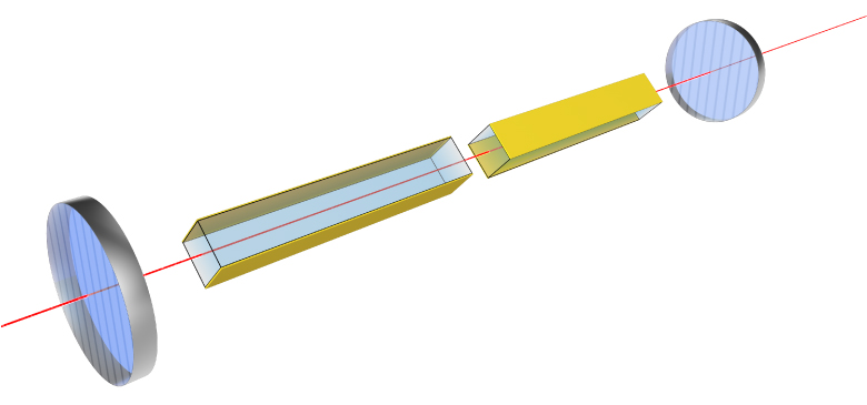
Click to Enlarge
Amplitude Modulator Crystal Orientation
Note: Polarizers must be purchased separately.
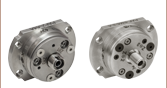
Our EO amplitude modulators are Pockels cell-type modulators consisting of two matched lithium niobate crystals (see the diagram to the right) packaged in a compact housing with an RF input connector. The EO crystals act as a variable waveplate with a retardance that is dependent on the applied electric field. When placed between linear polarizers, the beam intensity through the system varies with the applied voltage. See the EO Modulator Intro tab for a detailed explanation.
Please note that AM modulators operating in the -C4 band (400 - 600 nm) should only be used for AC modulation above a few Hz. MgO-doped lithium niobate can be sensitive to light in this wavelength range, displaying a slow negation to an applied DC field. The more intense the light, the faster the DC field is cancelled. Hence, in practice, a DC voltage cannot be used to bias the modulator at the desired operating point. Instead, an optical compensator can bias the modulator to the desired operating point (please see the EO Modulator Intro tab for more information on proper modulator biasing).

 Zoom
Zoom
Our EO phase modulators introduce an electrically controlled phase shift to a linearly polarized input beam. The control signal may be DC or time varying. When the control voltage is time varying, the optical beam undergoes frequency modulation. In this case, some of the energy at the fundamental optical frequency is converted into sidebands that are separated by integer multiples of the modulating frequency. The modulation depth determines the amount of energy converted into these sidebands. The graph to the right shows the relative sideband power as a function of modulation depth.

 Zoom
Zoom
Click to Enlarge
The plot above corresponds to a
standard 20 MHz resonant modulator. Modulators
with different resonant frequencies will have
different Q values.
Our resonant EO phase modulators feature an internal, high-Q tank circuit that boosts a low-level RF input voltage to the high voltage needed to achieve full modulation depth. As a result, they can be driven by a standard laboratory function generator. At 633 nm, for example, this gives a Q value of 14 and a half-wave voltage of only 15 V.
We offer standard resonant modulators in both phase- and amplitude-modulating versions, operating at 20 MHz with a 1 MHz bandwidth. They feature a -C1 coating for use from 600 to 900 nm. Custom versions are also available, with user-specified resonant frequencies from 0.1 to 100 MHz and with any of the standard C1 - C4 AR coatings. Note that the Q value is a function of the resonant frequency. Please contact

 Zoom
Zoom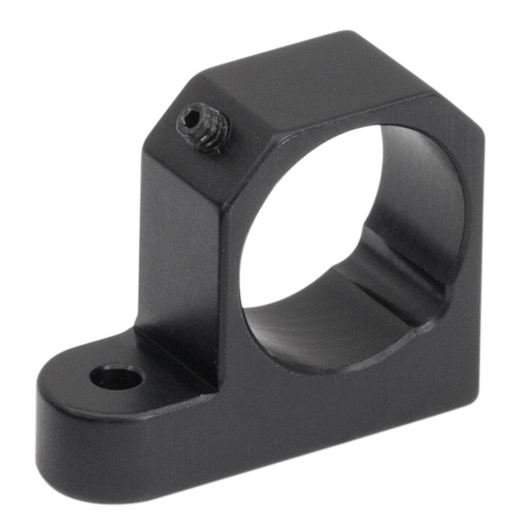
Click to Enlarge
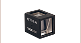
EO-PMT Polarizer Mounting Adapter
- GTH5M Mounting Adapter for Our Electro-Optic Modulators
- Easily Rotates Into and Out of Beam Path
- Ø13 mm Aperture for Use with GTH5M
- 2-56 Mounting Screw and Washer Included
The EO-PMT allows for easy interfacing of a Glan Thompson polarizer (GTH5M) to our Electro-Optic Modulators. The single mounting point allows the mount to swivel the polarizer into and out of the light path; a useful feature that allows for alignment and adjustment of the electro-optic modulators. The EO-GTH5M packages the Glan Thompson polarizer (GTH5M) with the mounting adapter.

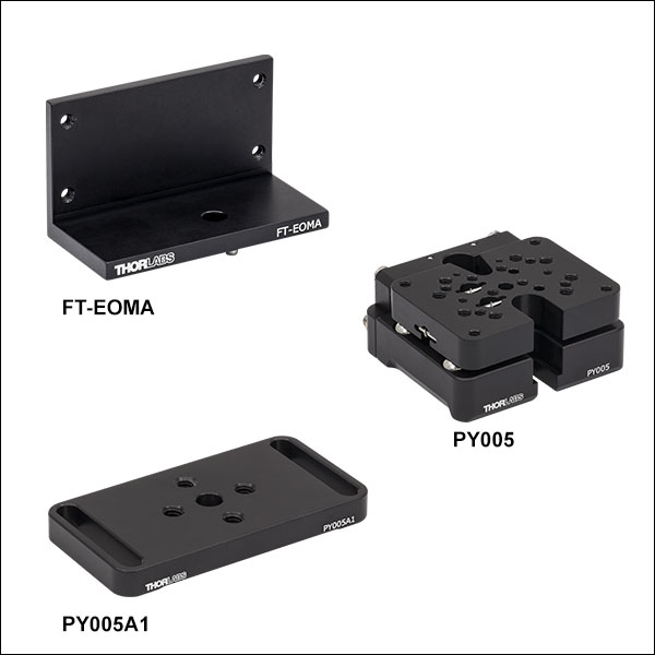 Zoom
Zoom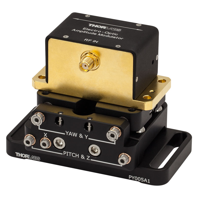
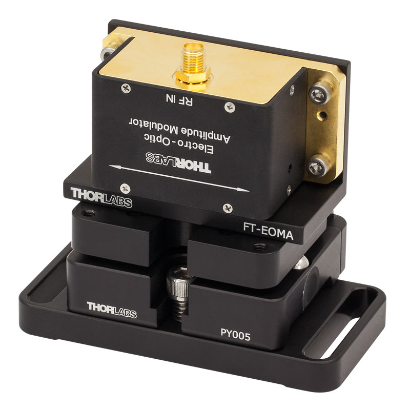
Our EO Modulators Can Be Mounted Using the PY005 5-Axis Stage, FT-EOMA Bracket and PY005A1 Base (Left) for a 2" (50.8 mm) Beam Height or Directly to the PY005 Stage (Right)
- Compact Platform with Five Axes of Adjustment
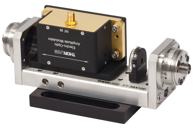
- Adapter Bracket Mounts Modulator to the Platform or any FiberBench Over 70 mm Long
- PY005A1 Mounting Base Mounts EO Modulators with a 2" (50.8 mm) Nominal Beam Height when used Together with the PY005 and and FT-EOMA
- Mounting Screws Included with All Mounting Adapters
The PY005 is a compact stage with five degrees of freedom. Two actuators adjust the yaw and Y axes, two actuators adjust the pitch and Z axes, and a single actuator adjusts the X axis. Two F19SC1 locking collars are epoxied onto the yaw and Y-axis actuators, acting as hard stops so these actuators cannot be overdriven. The pitch, X-axis, and Z-axis actuators bottom out inside bores, which prevents them from being overdriven. Please note that using F19SC1 collars with the pitch, X-axis, and Z-axis actuators is not recommended, as it will reduce the overall travel range of the stage. Click here for full information about the PY005 stage.
An EO modulator can be mounted directly to the PY005 using the #8 counterbore accessible from the bottom of the stage (shown to the far right). This counterbore is accessible even when the PY005A1 base is attached to the stage. Additionally, the EO modulator can be mounted to the stage using the FT-EOMA adapter bracket (shown to the immediate right). When the FT-EOMA is used to mount the modulator and the PY005A1 mounting base is attached to the bottom of the stage, the optical axis of the EO modulator is positioned at a nominal height of 2" (50.8 mm) from the optical table.
The FT-EOMA adapter bracket can also be used to mount a Modulator onto a FiberBench. The length of the bench needs to be at least 70 mm to mount the modulator. Incorporation of the optional EO Modulator optic mount and polarizer (EO-GTH5M) will require a longer FiberBench. The Linear Polarizer modules are well suited for use with an EO Modulator in a FiberBench System. The application picture to the right shows an EO Modulator with an FT-38X100 Multi-Axis FiberBench, one Linear Polarizer, and two FiberPorts.