 Products Home / Optomechanical Components / Optical Post Assemblies / Ø1/2" Optical Post Assemblies / Ø1/2" Universal Post Holders
Ø1/2" Universal Post Holders
- Precision Wide, Square Relief Provides a Highly
Stable Two-Line Contact with the Mounting Post - Each Post Holder Includes One Spring-Loaded
Hex Locking Thumbscrew
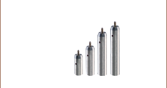
TS25H
UPH6
UPH4
UPH3
UPH2
UPH1.5
UPH1
Front
Back
UPH2
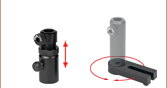
360° Continuously
Adjustable
Magnets in Base Provide Holding
Force Before Lock Down

Please Wait
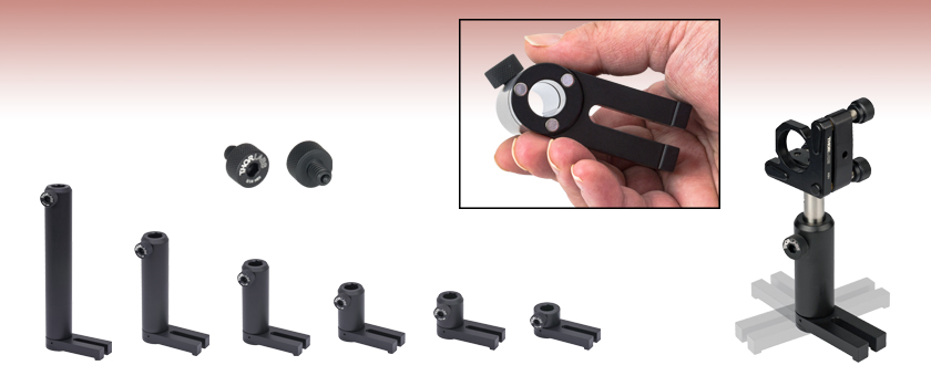
Figure 1.1 Universal Post Holder Features
Features
- Reduce Time to Construct Assemblies
- Spring-Loaded Thumbscrew Secures Post Prior to Final Locking
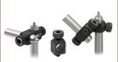
- Universal Post Holders Provide a Swiveling Clamping Fork and Magnetic Base for Easy Alignment
Thorlabs' Ø1/2" Universal Post Holders simplify the task of mounting a Ø1/2" optical post on an optical table or breadboard. These post holders incorporate a swiveling base, allowing a choice between multiple mounting holes on the breadboard. Magnets in the bottom of the base aid in rough alignment prior to final positioning. Additionally, the base is hollow, which allows the post to rest on the optical table and enables maximum height adjustment.
These Universal Post Holders have been designed with the same key features of our popular Standard Post Holders. They feature and extra wide square relief cut machined vertically along the length of the part, as shown in Figure 1.1. This channel provides a highly-stable two-line contact between the post and post holder. Other post holder designs that do not have a relief cut provide less holding power, which leads to a downward drift in the post's position with time. Each post holder comes with a 3/16" (5 mm) hex spring-loaded thumbscrew. Additional quantities can be purchased separately below.
Thorlabs' large selection of standard post holders can all be converted into universal post holders by using a Thorlabs swivel base adapter.

Insights into Best Lab Practices
Scroll down to read about a few things we consider when setting up lab equipment.
- Clamping Forks: Tip for Maximizing the Holding Force
- Optical Tables: Clamping Forks and Distortion of the Table's Surface
- Post Holders: Rectangular Channel in the Inner Bore
Click here for more insights into lab practices and equipment.
Clamping Forks: Tip for Maximizing the Holding Force
Click to Enlarge
Figure 173B More than half the total applied force (FTotal) holds the object, since L1 > L2. The height of the left leg of this CL2 clamp is variable to compensate for the object's height. This allows the clamp's top surface and the mounting surface to be made parallel.**
Click to Enlarge
Figure 173A Less than half the total applied force (FTotal) holds the object, since L1 < L2. The clamp illustrated here is the CL5A.
Clamped objects can be fairly easy to move when the torqued screw in the clamp's slot is positioned too far from the object. Correct positioning of the screw protects clamped objects from being knocked out of position.
To maximize the clamping force, position the screw as close as possible to the object.**
This works since clamps like CL5A and CL2 (Figures 173A and 173B, respectively) divide the torqued screw's applied force (FTotal) between two points.
Clamping force F2 is applied to the object. The value of F2 is a percentage of FTotal and depends on L1 and L2, as described below. The remainder (F1) of the total force is applied through the opposite end of the clamp.
The following equations can be used to calculate the two applied forces.
Object: |
 |
|
| Force Applied to Other Contact Point: |
 |
These equations show that the clamping force on the object increases as the distance between the object and screw decreases. The force supplied by the torqued screw is evenly divided between F1 and F2 when L1 and L2 are equal.
**Note that maximizing the clamping force also requires both the top surface of the clamp and the area it contacts on the object to be parallel with the mounting surface, as depicted in Figures 173A and 173B.
If the tangent at the interface between the clamp and object is not parallel to the mounting surface, the force applied to the object will be divided between pressing it into and pushing it across the mounting surface. The force directed along the mounting surface may, or may not, be sufficient to translate the object.
To accommodate different object heights, clamps like the CL2 have one threaded, variable-length leg, which is shown on the left in Figure 173B. The number of threads between the clamp and mounting surface should be adjusted to compensate for the height of the object and to keep the clamp's top surface level with the table.
Date of Last Edit: Dec. 4, 2019
Optical Tables: Clamping Forks and Distortion of the Table's Surface
Click to Enlarge
Figure 173C The construction of a Nexus table / breadboard includes a (1) top skin, (2) bottom skin, (3) side finishing trim, (4) side panels, and (5) honeycomb core. The stainless steel top and bottom skins are 5 mm thick.
Clamping forks are more rigid than the mounting surface of composite optical tables. It might be expected that the spine of the clamping fork would bend with the force exerted by the screw as the torque is increased. Instead, the screw will pull the skin of the table up and out of flat before the clamping fork deforms. Due to this, clamping forks should be used with care when securing components to optical tables. Clamping arms, which are discussed in the following, are alternatives to clamping forks that are less likely to deform the table's mounting surface.
Optical Table Construction
Optical tables and breadboards with composite construction (Figure 173C) are designed to be rigid while providing vibration damping. The 5 mm thick, stainless steel top skin is manufactured to be flat, but a localized force can deform it. When the top skin is deformed, optical components will not sit flat, and optical system alignment and performance can be negatively affected.
Clamping Forks
Standard clamping forks are installed with one edge placed on the table's surface and the opposite edge on the object (Figure 173D). Between these two edges, there is clearance between the bottom of the clamp and the surface of the table. This bridge makes it possible to use a single screw to both secure the clamp to the table and exert a holding force on the object.
When the clamp is secured by torqueing the screw, the screw pulls up on the top skin of the table (Figure 173E).
As the torque on the screw increases, the top skin of the table rises. Not only does pulling up on the table surface risk permanently damaging the table, this can also disturb the alignment of the optical component the clamp is being used to secure. By lifting the table's skin, the mounting surface under the clamped object tilts.

Click to Enlarge
Figure 173F The POLARIS-CA1/M clamping arm has a slot that accepts a mounting screw, a separate screw that applies a clamping force to an installed post, and identical top and bottom surfaces. Since a nearly continuous track around the surface of the clamping arm is in contact with the mounting surface, clamping arms cause negligible bridging effects.
Click to Enlarge
Figure 173E Torqueing the screw creates a force that pulls up on the table's top skin. The lifted skin tilts the mounting surface and can induce angular deviation of the object. This effect is exaggerated in this image for illustrative purposes.
Click to Enlarge
Figure 173D A standard clamping fork, such as the CL5A, contacts the table along only one edge. The opposite edge is in contact with the object to be secured. A bridge forms between the two. The screw that applies the clamping force is not shown.
Clamping Arms
Clamping arms, such as the POLARIS-CA1/M, shown in Figure 173F, are designed to secure a post while minimally deforming the mounting surface.
The clamping arm in Figure 173F differs from clamping forks in two significant ways. One is the surface area that makes contact with the optical table, which is highlighted in red, and the other is the method used to secure the post.
The area in contact with the optical table makes a nearly continuous loop around the base of the clamp. The contact area is flat and flush with the table when the clamp is installed. The only break in the loop is a narrow slot in the vise used to grip the post.
This design uses two screws, instead of the clamping fork's single screw. One screw (not shown) secures the clamp to the table, and the other (indicated) is tightened to grip the post. Since one screw is not required to perform both tasks, it is not necessary for this clamping arm to form a bridge between the clamped object and the optical table.
Although the contact area is a loop, and not a solid surface, this clamp causes negligible distortion of the mounting surface. This is due to the open area inside the contact surface being narrow and surrounded by the sides of the clamp, which resist the force pulling up on the table.
Date of Last Edit: Dec. 4, 2019
Post Holders: Rectangular Channel in the Inner Bore
Click to Enlarge
Figure 173H Top view. The three contact locations between the post and post holder, highlighted in red, prevent the post from translating or rotating around the X or Y axes. Friction resists the post's translation and rotation around the Z axis.

Click to Enlarge
Figure 173G A channel with sharp edges is machined into the inner bore of Thorlabs' post holders.
Figure 173J A broach, such as the one illustrated here, has a row of teeth, the next taller than the previous. With the teeth in contact with the material, a machine pulls the broach across the surface. Each tooth removes a small amount of material, and the depth of the channel created by the broach equals the overall difference in tooth height.
All of Thorlabs' post holders include a channel, with straight parallel edges, running the length of the inner bore (Figure 173G). Tightening the setscrew pushes the post against the two edges of the channel (Figure 173H). Since the edges of the channel are separated by a wide distance, approximately half the inner diameter of the post holder, the seating of the post against the channel's edges is stable and repeatable.
Contact with the two edges of the channel eliminates four of the post's six degrees of freedom, since the edges block the post from translating along or rotating around either the Y or Z axis. In addition, the friction between the side of the post and the edges of the channel resists the post's movement along and around the X axis, which are the post's two remaining degrees of freedom.
Without the channel in the inner bore, there would be a single line of contact between the post and post holder. The position of the post would not be stable, since the post would be free to rotate around the Z axis and shift along the Y axis.
Even if this instability resulted in submicron-scale unwanted shifts in each component's position in an optical setup, the cumulative effect could have a significant negative impact on system performance. In addition, more frequent realignment of the system could be required.
Broaching
The channel's edges must be straight and free of bumps and roughness to hold the post stable. These post holders have straight, sharp edges when examined on a micron scale. If the edges are not completely linear, the post might rock in the holder, and / or it may not be possible to repeatably position the post in the holder.
The smooth, straight edges of the channel are achieved using a machining process called broaching. A broach (Figure 173J) resembles a saw whose teeth increase in height along its length.
As the broach is pulled along a surface, each tooth removes a small amount of material. The total depth of the channel cut by the broach equals to the overall difference in tooth height (H2 - H1).
Compared with other approaches for creating channels, broaching is preferred due to its ability to provide straight profiles while being compatible with high-volume production.
Date of Last Edit: Dec. 11, 2019
| Posted Comments: | |
tcohen
(posted 2012-02-29 15:51:00.0) Response from Tim at Thorlabs: Thank you for your feedback. The TR50/M will be able to fit in the UPH2/M and you will be able to adjust its height with the thumbscrew. However, because the length of the post is shorter than the length of the post holder, the TR50/M will be under the top of the UPH2/M when sitting near the bottom. If this is a concern, we do offer shorter UPH at http://www.thorlabs.com/NewGroupPage9.cfm?ObjectGroup_ID=1982&pn=UPH1 and taller posts at http://www.thorlabs.com/NewGroupPage9.cfm?ObjectGroup_ID=1266. user
(posted 2012-02-28 11:55:56.0) TR50/M (50 mm) is compatible with UPH2/M(50.8 mm) or not? Is it possible to use TR50/M (50 mm) with UPH2/M(50.8 mm)? Thank you. mathieu.perrin
(posted 2010-03-24 16:37:30.0) The universal post holder is a component I personally highly recommend. No need to find a clamp, no need to change everything when you realize youre not right in front of the hole, magnets give a certain stiffness while allowing to move the optics parallel to the table : setting up an experiment suddenly becomes twice easier! |

 Zoom
Zoom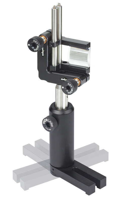
- Base Swivels 360° for Mounting Convenience
- Post can Pass Through Base, Enabling Minimum Beam Height
- Magnets in Base Provide Holding Force Prior to Fastening to an Optical Table
- Spring-Loaded Hex Locking Thumbscrews for Positioning Ease
- Packs of 5 Also Available for 1" to 3" Lengths (30 mm to 75 mm)
Our line of Universal Post Holders offers several convenient features that make it easy to construct a new assembly. The swiveling base allows you to place your optic mount at the desired location and then simply swivel the base until it lines up with a convenient mounting hole on the optical table. Additionally, the post holder base is equipped with magnets that provide holding force for rough optic alignment prior to final lockdown. For additional height adjustment, the hollow base allows a Ø1/2" Post to rest upon the optical table, allowing the largest range of height adjustment of the post. These post holders are equipped with a TS25H(/M) 3/16" (5 mm) drive spring-loaded hex locking thumbscrew. This thumbscrew should not be tightened beyond the maximum torque of 28 in·lbs (3.2 N·m). Popular post holders are also available in packages of five for ease of ordering.
To order these post holders without magnets, please contact Tech Support.

 Zoom
Zoom| Specification | |
|---|---|
| Maximum Torquea | 28 in·lbs (3.2 N·m) |

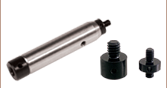
Click to Enlarge
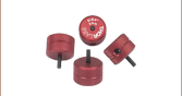
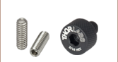
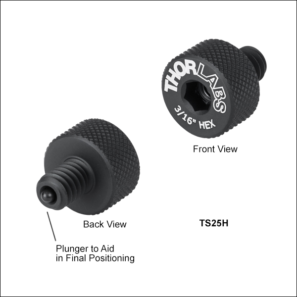
Figure 214B Exploded View of the TS25H Thumbscrew
Figure 214A TS25H Drawing
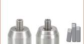
The TS25H has 1/4"-20 threads while the TS6H/M has M6 x 1.0 threads for compatibility with our imperial and metric Ø1/2" post holders, respectively. The recommended maximum torque is 28 in·lbs (3.2 N·m). Please note that we do not recommend using an L wrench to tighten the thumbscrew, as this may break off the screw head.
If a thumbscrew without a spring-loaded tip is preferred, we recommend our vacuum-compatible thumbscrews. Alternatively, the tips can be removed from these thumbscrews by unthreading the setscrew in the front of the thumbscrew with a 1/16" (1.5 mm)
For ease of ordering, these thumbscrews are available individually or in packages of five.
*Delrin® is a registered trademark of DuPont Polymers, Inc.

 Zoom
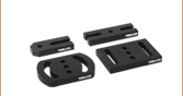
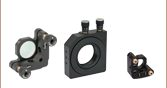
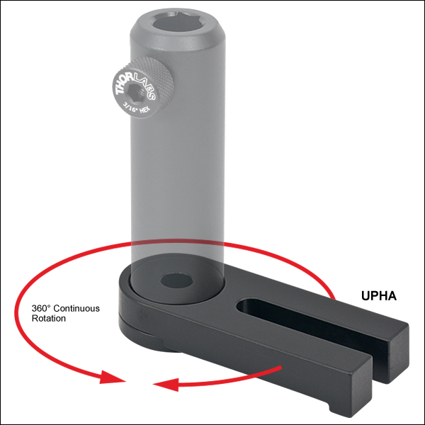
Zoom- Convert Ø1/2" Post Holders into Universal Post Holder Style Mounts
- 360° Swiveling Base Fastens to Existing Post Holders via a 1/4"-20 (M6) Cap Screw
- Magnets in Base Hold Position of Components on Breadboard During Initial Setup
- Also Available in Packs of Five
Our 360° swivel base adapter adds the swivel and magnetic retention functionality of our universal post holders to our standard Ø1/2" post holders. This allows users to minimize the amount of time it takes to assemble an optical system. In addition, the swivel design is ideal for applications that require a large number of components to be packed into a small area. Please note that this anodized aluminum adapter does not offer the same height flexibility of the universal post holders above, which allow the post to be lowered all the way to the table.