 Products Home / Optomechanical Components / Optical Post Assemblies / Bases / Table Clamps / Table Clamps
Table Clamps
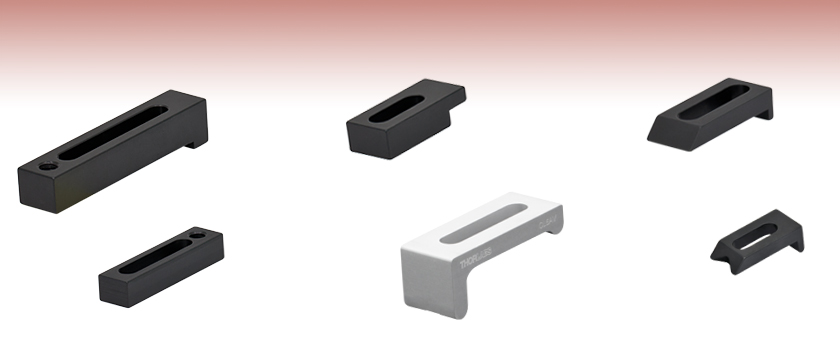
- Versatile and Distinct Designs to Secure Components to Tables and Breadboards
- Vacuum-Compatible Versions Available
- Solid One-Piece Construction
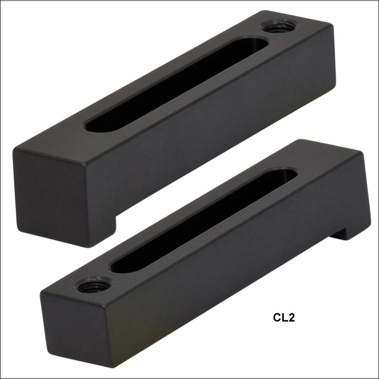
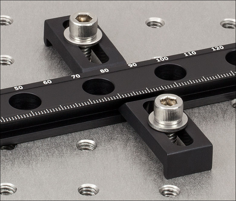
CL2
Our Most Popular
Heavy-Duty Clamp
CL3
Compact
Clamp with
Variable Height
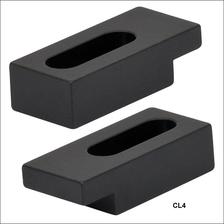
CL4
For Tight Spaces
CL5AV
Vacuum-Compatible General-Purpose Clamp
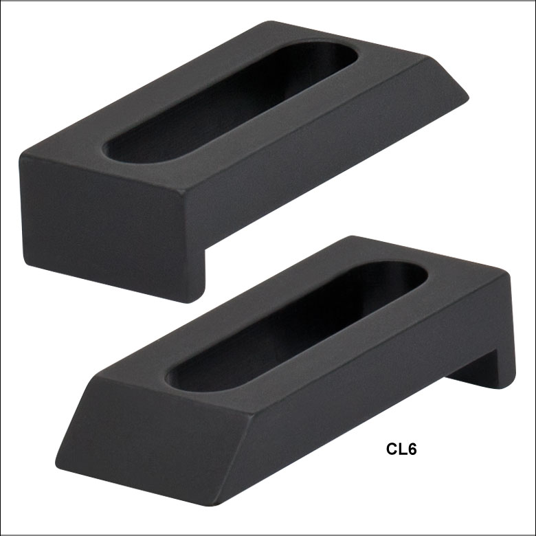
CL6
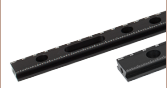
For Dovetail Optical Rails
CL8
For Ø1" and
Ø1.5" Pedestal Posts


Please Wait
| Item # | Component Thickness | |
|---|---|---|
| Minimum | Maximum | |
| CL2(/M) CL2V(/M) |
Variablea | |
| CL3(/M) CL3V(/M) |
Variablea | |
| CL4 CL4V |
0.02" (0.5 mm) | 0.25" (6.4 mm) |
| CL5 | 0" | 0.50" (12.7 mm) |
| CL5A CL5AV |
0" | 0.80" (20.3 mm) |
| CL6 CL6V |
0" | 0.25" (6.4 mm) |
| XE25CL2 | For 25 mm Railsb | |
| CL8 CL8V |
0" | 0.30" (7.6 mm) |
Options
- CL2(V): Heavy-Duty Clamp with Adjustable Height
- CL3(V): Compact Clamp with Adjustable Height
- CL4(V): Compact Clamp for Tight Spaces
- CL5 and CL5A(V): General-Purpose Clamps
- CL6(V): Wedged for Use with Dovetail Optical Rails
- XE25CL2: Hooked Lip for Use with 25 mm Rails
- CL8(V): Table Clamp for Ø1" and Ø1.5" Pedestal Posts
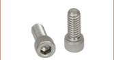
Thorlabs' Table Clamps are useful when constructing optomechanical assemblies. The design of our clamps helps to reduce an assembly's setup time by adapting complex layouts to any mounting hole pattern. Each clamp is suitable for securing bases and other optomechanical components with thicknesses in the ranges specified in the table to the right. These clamps are used with 1/4"-20 (M6) cap screws and washers, which are available as part of our Screw Kits.
We also offer vacuum-compatible versions of the CL2(/M), CL3(/M), CL4, CL5A, CL6, and CL8 clamps.
For added convenience, the CL2(/M), CL3(/M), CL5, CL5A, and all vacuum-compatible clamps are also sold in packs of 5.
Additional Vacuum-Compatible Components
Many of our other optomechanical components can be special ordered for vacuum use. Contact techsales@thorlabs.com for details.

Insights into Best Lab Practices
Scroll down to read about a few things we consider when setting up lab equipment.
- Clamping Forks: Tip for Maximizing the Holding Force
- Optical Tables: Clamping Forks and Distortion of the Table's Surface
Click here for more insights into lab practices we follow.
Clamping Forks: Tip for Maximizing the Holding Force
Click to Enlarge
Figure 2: More than half the total applied force (FTotal) holds the object, since L1 > L2. The height of the left leg of this CL2 clamp is variable to compensate for the object's height. This allows the clamp's top surface and the mounting surface to be made parallel.**
Click to Enlarge
Figure 1: Less than half the total applied force (FTotal) holds the object, since L1 < L2. The clamp illustrated above is the CL5A.
Clamped objects can be fairly easy to move when the torqued screw in the clamp's slot is positioned too far from the object. Correct positioning of the screw protects clamped objects from being knocked out of position.
To maximize the clamping force, position the screw as close as possible to the object.**
This works since clamps like CL5A and CL2 (Figures 1 and 2, respectively) divide the torqued screw's applied force (FTotal) between two points.
Clamping force F2 is applied to the object. The value of F2 is a percentage of FTotal and depends on L1 and L2, as described below. The remainder (F1) of the total force is applied through the opposite end of the clamp.
The following equations can be used to calculate the two applied forces.
Object: |
 |
|
| Force Applied to Other Contact Point: |
 |
These equations show that the clamping force on the object increases as the distance between the object and screw decreases. The force supplied by the torqued screw is evenly divided between F1 and F2 when L1 and L2 are equal.
**Note that maximizing the clamping force also requires both the top surface of the clamp and the area it contacts on the object to be parallel with the mounting surface, as depicted in Figures 1 and 2.
If the tangent at the interface between the clamp and object is not parallel to the mounting surface, the force applied to the object will be divided between pressing it into and pushing it across the mounting surface. The force directed along the mounting surface may, or may not, be sufficient to translate the object.
To accommodate different object heights, clamps like the CL2 have one threaded, variable-length leg, which is shown on the left in Figure 2. The number of threads between the clamp and mounting surface should be adjusted to compensate for the height of the object and to keep the clamp's top surface level with the table.
Date of Last Edit: Dec. 4, 2019
Optical Tables: Clamping Forks and Distortion of the Table's Surface
Click to Enlarge
Figure 3: The construction of a Nexus table / breadboard includes a (1) top skin, (2) bottom skin, (3) side finishing trim, (4) side panels, and (5) honeycomb core. The stainless steel top and bottom skins are 5 mm thick.
Clamping forks are more rigid than the mounting surface of composite optical tables. It might be expected that the spine of the clamping fork would bend with the force exerted by the screw as the torque is increased. Instead, the screw will pull the skin of the table up and out of flat before the clamping fork deforms. Due to this, clamping forks should be used with care when securing components to optical tables. Clamping arms, which are discussed in the following, are alternatives to clamping forks that are less likely to deform the table's mounting surface.
Optical Table Construction
Optical tables and breadboards with composite construction (Figure 3) are designed to be rigid while providing vibration damping. The 5 mm thick, stainless steel top skin is manufactured to be flat, but a localized force can deform it. When the top skin is deformed, optical components will not sit flat, and optical system alignment and performance can be negatively affected.
Clamping Forks
Standard clamping forks are installed with one edge placed on the table's surface and the opposite edge on the object (Figure 4). Between these two edges, there is clearance between the bottom of the clamp and the surface of the table. This bridge makes it possible to use a single screw to both secure the clamp to the table and exert a holding force on the object.
When the clamp is secured by torqueing the screw, the screw pulls up on the top skin of the table (Figure 5).
As the torque on the screw increases, the top skin of the table rises. Not only does pulling up on the table surface risk permanently damaging the table, this can also disturb the alignment of the optical component the clamp is being used to secure. By lifting the table's skin, the mounting surface under the clamped object tilts.
Click to Enlarge
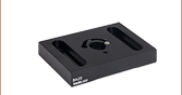
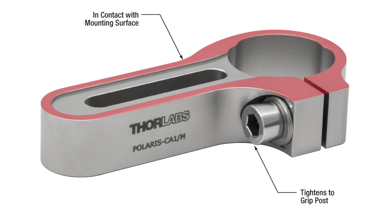
Figure 6: The POLARIS-CA1/M clamping arm has a slot that accepts a mounting screw, a separate screw that applies a clamping force to an installed post, and identical top and bottom surfaces. Since a nearly continuous track around the surface of the clamping arm is in contact with the mounting surface, clamping arms cause negligible bridging effects.
Click to Enlarge
Figure 5: Torqueing the screw creates a force that pulls up on the table's top skin. The lifted skin tilts the mounting surface and can induce angular deviation of the object. This effect is exaggerated in the above image for illustrative purposes.
Click to Enlarge
Figure 4: A standard clamping fork, such as the CL5A, contacts the table along only one edge. The opposite edge is in contact with the object to be secured. A bridge forms between the two. The screw that applies the clamping force is not shown.
Clamping Arms
Clamping arms, such as the POLARIS-CA1/M, shown in Figure 6, are designed to secure a post while minimally deforming the mounting surface.
The clamping arm in Figure 6 differs from clamping forks in two significant ways. One is the surface area that makes contact with the optical table, which is highlighted in red, and the other is the method used to secure the post.
The area in contact with the optical table makes a nearly continuous loop around the base of the clamp. The contact area is flat and flush with the table when the clamp is installed. The only break in the loop is a narrow slot in the vise used to grip the post.
This design uses two screws, instead of the clamping fork's single screw. One screw (not shown) secures the clamp to the table, and the other (indicated) is tightened to grip the post. Since one screw is not required to perform both tasks, it is not necessary for this clamping arm to form a bridge between the clamped object and the optical table.
Although the contact area is a loop, and not a solid surface, this clamp causes negligible distortion of the mounting surface. This is due to the open area inside the contact surface being narrow and surrounded by the sides of the clamp, which resist the force pulling up on the table.
Date of Last Edit: Dec. 4, 2019
| Posted Comments: | |
Fabian Meylahn
(posted 2022-11-09 09:25:01.58) Dir Sir or Madam,
can you offer the L clamps CL5 or CL5A in a vacuum compatible version? Like BA1V.
If yes, what would be the approximated price and delivery time for 40 clamps?
Thank you for your efforts.
Best regards,
Fabian Meylahn cdolbashian
(posted 2022-11-10 12:56:43.0) Thank you for reaching out to us Fabian. I have contacted you directly to work out the details regarding your inquiry. user
(posted 2022-02-08 11:13:37.677) The best table clamp ever made. Bring it back!!! jdelia
(posted 2022-02-08 04:32:42.0) Thank you for contacting Thorlabs. It is great to hear such great feedback from an old part. I am happy to pass this along to our internal product development team to inquire on the possibility of a re-release. jhigbie
(posted 2015-07-24 21:03:50.95) I think it would be very useful to have some smaller versions of these clamps. For example, to attach odd-shaped mounts/objects to translation stages, when the hole pattern doesn't allow directly screwing them in. For some purposes, the length of the CL4 or CL6 is just too great, and a shorter clamp (perhaps with a 8-32 clamping screw) would be very handy. ( I just machined a couple such clamps today to clamp a piezo stage on a Thorlabs mechanical stage, but would rather buy them from Thorlabs...) besembeson
(posted 2015-09-23 06:22:52.0) Response from Bweh at Thorlabs USA: We have the mini series general purpose clamps, the MSCL3 for example that uses a #4-40 cap screw if the CL4 and CL6 are too large. I will contact you to find out what stage this was used for and the general dimensions of the clamp you machined so that we can look into filling the #8-32 cap screw gap to serve more users. jlow
(posted 2012-10-09 11:05:00.0) Response from Jeremy at Thorlabs: The drawing for the CL2 can be found at http://www.thorlabs.com/Thorcat/0100/CL2-AutoCADPDF.pdf, which have all the dimensions that you are looking for. The SolidWorks model can be found at http://www.thorlabs.com/Thorcat/0100/CL2-Solidworks.sldprt. gregori.monoenko
(posted 2012-10-09 10:20:58.0) what is the width of cl2?
what is the location of the 1/4-20 tap?
what is the location and dimension of the slot?
I have to model this part and add it to the assembly .
thanks,
greg monoenko |

 Zoom
Zoom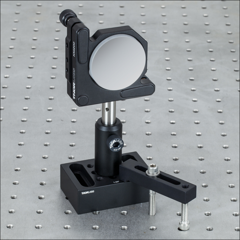
Click for Details CL2 Clamp Holding BA2S7 Spacer on Table
Click for Details
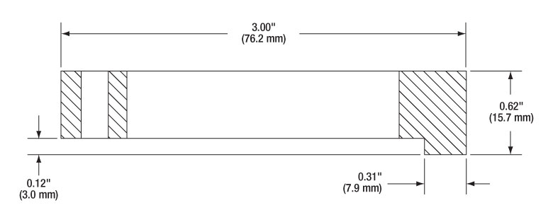
CL2(/M) Cross-Sectional View
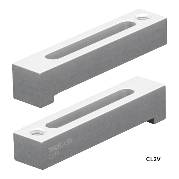
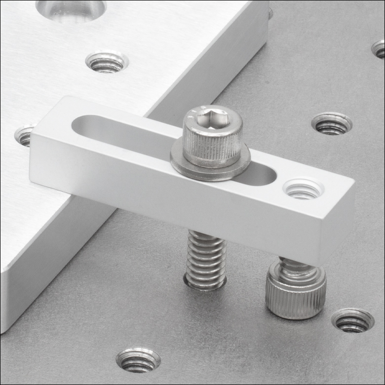
The CL2(/M) heavy-duty table clamp uses two cap screws: one in the 1/4"-20 (M6) tapped hole to adapt the clamp to virtually any height and another in the slotted hole to secure the clamp to the table. The extra-long design increases the force exerted on the optomechanic being held.
The thickness of optomechanical components that can be used with the CL2(/M) clamp depends on the length of the screws used to secure the clamp.
For added convenience, the CL2(/M) is also sold in packs of 5.

 Zoom
Zoom| Vacuum Specifications | |
|---|---|
| Vacuum Compatibility as Packageda |
>10-6 Torr |
| Materials | 6061-T6 Aluminum |
| Preparation and Packaging |
Wiped with Alcohol and Double Vacuum Bagged |
| Aluminum Outgassing Rate at 20 °C |
7.6 x 10⁻⁹ Torr-Liters/s/cm2 |
Click for Details
CL2V(/M) Cross-Sectional View
The CL2V(/M) heavy-duty table clamp is a vacuum-compatible version of our CL2(/M) clamp. It uses two cap screws: one in the 1/4"-20 (M6) tapped hole to adapt the clamp to virtually any height and another in the slotted hole to secure the clamp to the table. The extra-long design increases the force exerted on the optomechanic being held.
The thickness of optomechanical components that can be used with the CL2V(/M) clamp depends on the length of the screws used to secure the clamp.
The CL2V(/M) is prepared for vacuum applications before packaging in a cleanroom environment. It is compatible directly out of the packaging with vacuum environments down to 10-6 Torr. With additional cleaning and processing, it can be used at even lower pressures, only limited by the outgassing rate of the aluminum (see the table to the right). The material properties of the aluminum and the cleaning methods completed by the end user should be used to determine the appropriateness of these products and materials in a specific vacuum system.
The CL2V(/M) is sold in packs of 5.

 Zoom
Zoom

Click Details
CL3(/M) Cross-Sectional View
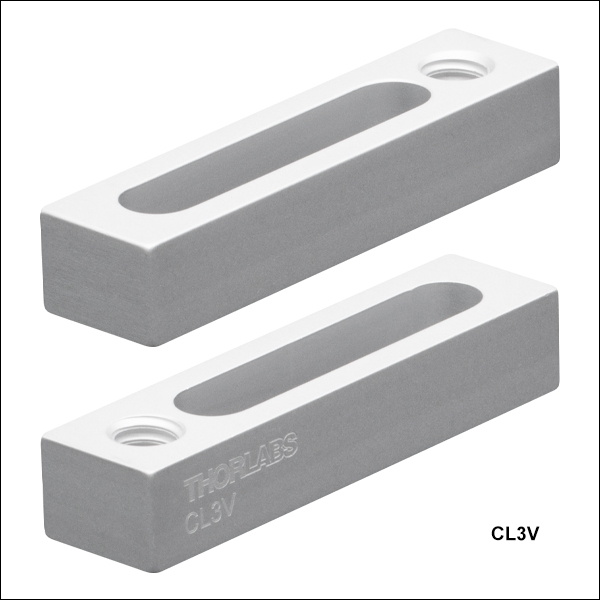
The CL3(/M) table clamp uses two cap screws: one in the 1/4"-20 (M6) tapped hole to adapt the clamp to virtually any height and another in the slotted hole to secure the clamp to the table. Its compact design reduces the footprint of the clamp relative to the CL2(/M).
The thickness of optomechanical components that can be used with the CL3(/M) clamp depends on the length of the screws used to secure the clamp.
For added convenience, the CL3(/M) is also sold in packs of 5.

 Zoom
Zoom| Vacuum Specifications | |
|---|---|
| Vacuum Compatibility as Packageda |
>10-6 Torr |
| Materials | 6061-T6 Aluminum |
| Preparation and Packaging |
Wiped with Alcohol and Double Vacuum Bagged |
| Aluminum Outgassing Rate at 20 °C |
7.6 x 10⁻⁹ Torr-Liters/s/cm2 |
Click Details
CL3V(/M) Cross-Sectional View
The CL3V(/M) table clamp is a vacuum-compatible version of our CL3(/M) clamp. It uses two cap screws: one in the 1/4"-20 (M6) tapped hole to adapt the clamp to virtually any height and another in the slotted hole to secure the clamp to the table. Its compact design reduces the footprint of the clamp relative to the CL2V(/M).
The thickness of optomechanical components that can be used with the CL3V(/M) clamp depends on the length of the screws used to secure the clamp.
The CL3V(/M) is wiped with alcohol and prepared for vacuum applications before packaging in a cleanroom environment. It is compatible directly out of the packaging with vacuum environments down to 10-6 Torr. With additional cleaning and processing, it can be used at even lower pressures, only limited by the outgassing rate of the aluminum (see the table to the right). The material properties of the aluminum and the cleaning methods completed by the end user should be used to determine the appropriateness of these products and materials in a specific vacuum system.
The CL3V(/M) is sold in packs of 5.

 Zoom
Zoom
Click for Details
CL4 Cross-Sectional View
At just 1.38" long and 0.63" wide, the CL4 table clamp is our most compact table clamp option, designed for situations where table space is at a premium. It requires one cap screw and washer to secure.
This clamp can be used with optomechanical components with a thickness up to 0.25".

 Zoom
Zoom| Vacuum Specifications | |
|---|---|
| Vacuum Compatibility as Packageda |
>10-6 Torr |
| Materials | 6061-T6 Aluminum |
| Preparation and Packaging |
Wiped with Alcohol and Double Vacuum Bagged |
| Aluminum Outgassing Rate at 20 °C |
7.6 x 10⁻⁹ Torr-Liters/s/cm2 |
Click for Details
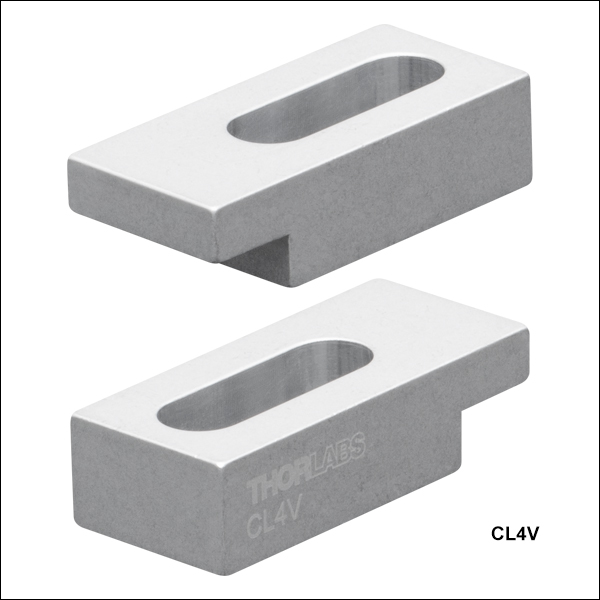
CL4V Cross-Sectional View
The CL4V table clamp is a vacuum-compatible version of the CL4 clamp. At 1.38" long and 0.63" wide, it is designed for situations where table space is at a premium. It requires one cap screw and washer to secure.
This clamp can be used with optomechanical components with a thickness up to 0.25".
The CL4V is wiped with alcohol and prepared for vacuum applications before packaging in a cleanroom environment. It is compatible directly out of the packaging with vacuum environments down to 10-6 Torr. With additional cleaning and processing, it can be used at even lower pressures, only limited by the outgassing rate of the aluminum (see the table to the right). The material properties of the aluminum and the cleaning methods completed by the end user should be used to determine the appropriateness of these products and materials in a specific vacuum system.
The CL4V is sold in packs of 5.

 Zoom
Zoom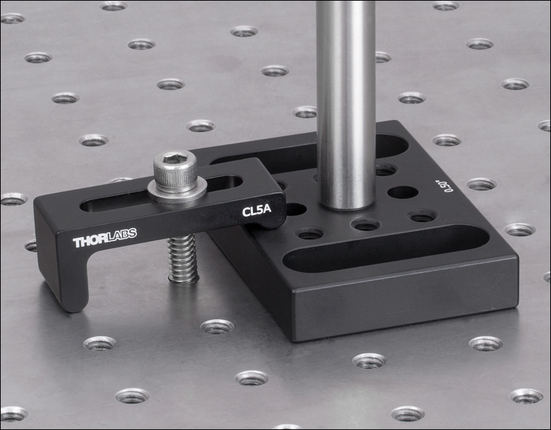
Click for Details CL5A Clamp Holding Down a BA2S6 0.5" Thick Base
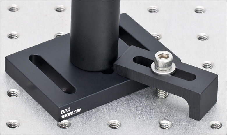
Click for Details CL5 Clamp Holding Down a BA2 Base
Click for Details
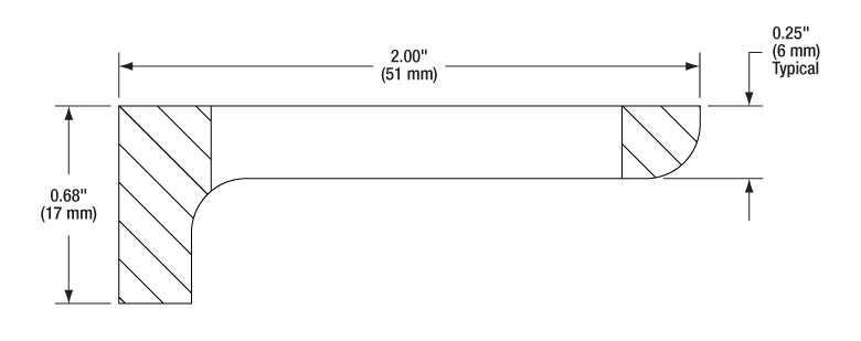
CL5 Cross-Sectional View
Click for Details
CL5A Cross-Sectional View
The CL5 table clamp has a simple design that is compatible with most common optomechanics. It only requires one cap screw and washer to secure. This clamp can be used with optomechanical components with a thickness up to 0.50".
The CL5A table clamp is similar in design to the CL5, but a curved lip allows the clamp to be used with thicker optomechanical components. The CL5A can be used with components up to 0.80" thick. At higher clamping angles, the rounded edge remains in contact with the top of the component, rather than pushing against the corner. This maintains a downward force and prevents unwanted horizontal movement on the table. In addition, the bottom of the clamp has a rounded edge with a relief cut to allow for sturdier contact between the clamp and optical table, especially when the clamp is used at a high angle.
For added convenience, the CL5 and CL5A are also sold in packs of 5.

 Zoom
Zoom| Vacuum Specifications | |
|---|---|
| Vacuum Compatibility as Packageda |
>10-6 Torr |
| Materials | 6061-T6 Aluminum |
| Preparation and Packaging |
Wiped with Alcohol and Double Vacuum Bagged |
| Aluminum Outgassing Rate at 20 °C |
7.6 x 10⁻⁹ Torr-Liters/s/cm2 |
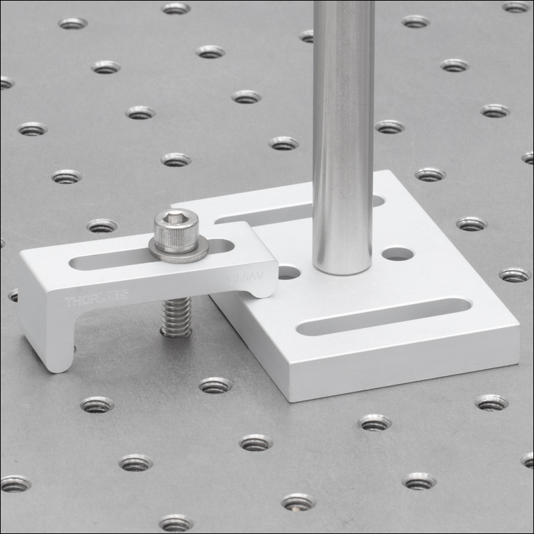
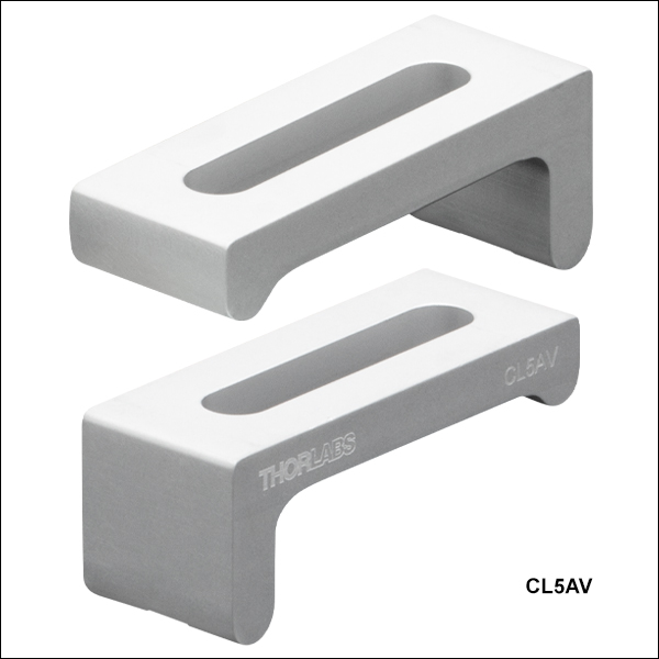
Click for Details CL5AV Clamp Holding Down a BA2V 3/8" Thick Base
Click for Details
CL5AV Cross-Sectional View
The CL5AV table clamp is a vacuum-compatible version of our CL5A clamp. It has a curved lip that allows the clamp to be used with components up to 0.80" thick. At higher clamping angles, the rounded edge remains in contact with the top of the component, rather than pushing against the corner. This maintains a downward force and prevents unwanted horizontal movement on the table. In addition, the bottom of the clamp has a rounded edge with a relief cut to allow for sturdier contact between the clamp and optical table, especially when the clamp is used at a high angle.
The CL5AV is wiped with alcohol and prepared for vacuum applications before packaging in a cleanroom environment. It is compatible directly out of the packaging with vacuum environments down to 10-6 Torr. With additional cleaning and processing, it can be used at even lower pressures, only limited by the outgassing rate of the aluminum (see the table to the right). The material properties of the aluminum and the cleaning methods completed by the end user should be used to determine the appropriateness of these products and materials in a specific vacuum system.
The CL5AV is sold in packs of 5.

 Zoom
Zoom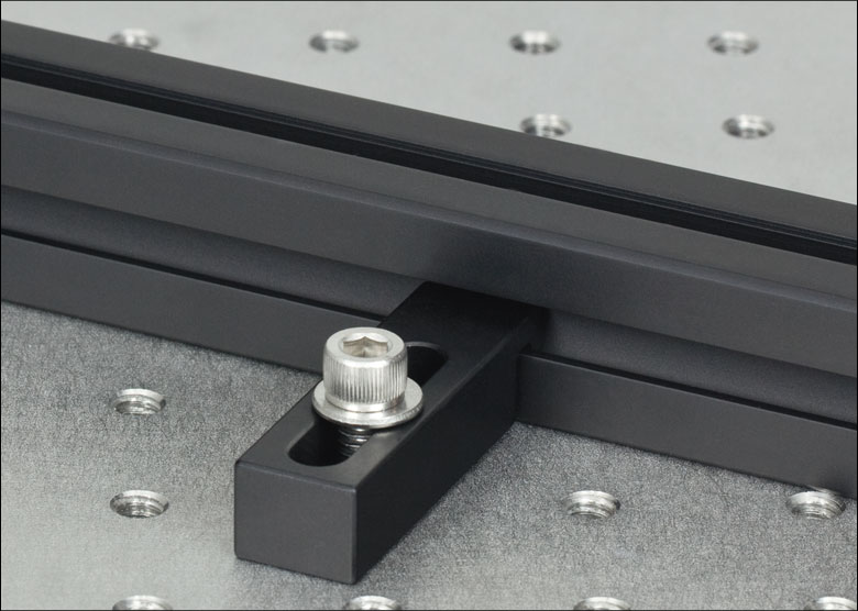
Click for Details
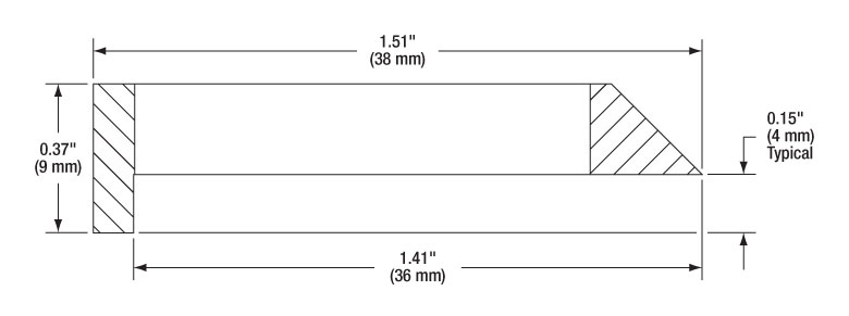
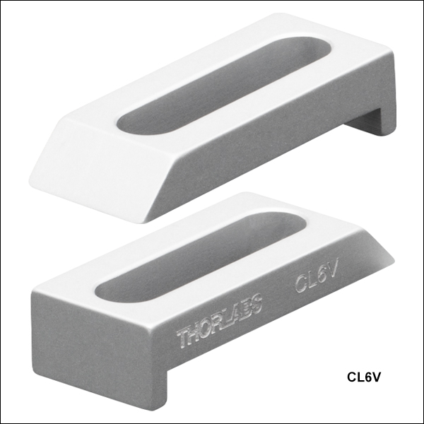
CL6 Cross-Sectional View
Click for Details
XE25CL2 Cross-Sectional View
The CL6 clamp features a wedged tip that is specifically designed to fit our dovetail optical rails, allowing a rail to be secured along any direction on a breadboard or optical table. The low-profile clamp has the same height as a dovetail rail, although its presence can restrict the placement of rail carriers. The CL6 clamp can be used with optomechanical components up to 0.25" thick.
The XE25CL2 Table Clamp mounts a 25 mm rail horizontally to a 1/4"-20 or M6 tapped surface by using a rail channel. It holds the rail in place using a side-located rail channel, while leaving the top rail channel free to accept enclosure panels or T-Nuts. The clamp features a 1" (25.4 mm) long clearance slot compatible with 1/4"-20 and M6 screws, providing mounting for imperial and metric tables.

 Zoom
Zoom| Vacuum Specifications | |
|---|---|
| Vacuum Compatibility as Packageda |
>10-6 Torr |
| Materials | 6061-T6 Aluminum |
| Preparation and Packaging |
Wiped with Alcohol and Double Vacuum Bagged |
| Aluminum Outgassing Rate at 20 °C |
7.6 x 10⁻⁹ Torr-Liters/s/cm2 |
Click for Details
CL6V Cross-Sectional View
The CL6V clamp is a vacuum-compatible version of our CL6 clamp. It features a wedged tip that is specifically designed to fit our dovetail optical rails, allowing a rail to be secured along any direction on a breadboard or optical table. The low-profile clamp has the same height as a dovetail rail, although its presence can restrict the placement of rail carriers. Please note that while the CL6V clamp is designed for use with the dovetail optical rails, that the rails themselves are not vacuum compatible. The CL6 clamp can be used with optomechanical components up to 0.25" thick.
The CL6V is wiped with alcohol and prepared for vacuum applications before packaging in a cleanroom environment. It is compatible directly out of the packaging with vacuum environments down to 10-6 Torr. With additional cleaning and processing, it can be used at even lower pressures, only limited by the outgassing rate of the aluminum (see the table to the right). The material properties of the aluminum and the cleaning methods completed by the end user should be used to determine the appropriateness of these products and materials in a specific vacuum system.
The CL6V is sold in packs of 5.

 Zoom
Zoom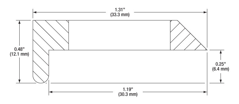
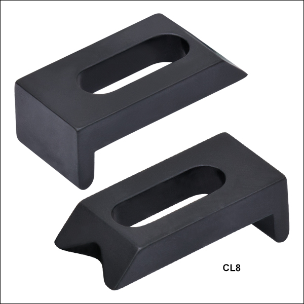
Click to Enlarge
CL8 Cross-Sectional View

The CL8 pedestal post table clamp is designed for use with our Ø1" and Ø1.5" pedestal posts. Its V-shaped tip provides two-point contact with the perimeter of the post and its rounded edge increases the contact area along the optical table or breadboard. It requires one cap screw and washer to secure.
The CL8 clamp can be used with optomechanical components up to 0.30" thick.

 Zoom
Zoom| Vacuum Specifications | |
|---|---|
| Vacuum Compatibility as Packageda |
>10-6 Torr |
| Materials | 6061-T6 Aluminum |
| Preparation and Packaging |
Wiped with Alcohol and Double Vacuum Bagged |
| Aluminum Outgassing Rate at 20 °C |
7.6 x 10⁻⁹ Torr-Liters/s/cm2 |
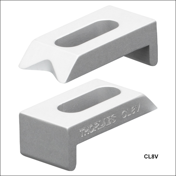
Click to Enlarge
CL8V Cross-Sectional View
The CL8V pedestal post table clamp is a vacuum-compatible veresion of the CL8. It is designed for use with our Ø1" and Ø1.5" pedestal posts. Its V-shaped tip provides two-point contact with the perimeter of the post and its rounded edge increases the contact area along the optical table or breadboard. It requires one cap screw and washer to secure. Please note that while the CL8V clamp is designed for use with the Ø1" and Ø1.5" pedestal posts, that the posts themselves are not vacuum compatible.
The CL8V clamp can be used with optomechanical components up to 0.30" thick.
The CL8V is wiped with alcohol and prepared for vacuum applications before packaging in a cleanroom environment. It is compatible directly out of the packaging with vacuum environments down to 10-6 Torr. With additional cleaning and processing, it can be used at even lower pressures, only limited by the outgassing rate of the aluminum (see the table to the right). The material properties of the aluminum and the cleaning methods completed by the end user should be used to determine the appropriateness of these products and materials in a specific vacuum system.
The CL8V is sold in packs of 5.