Cage Assembly Platforms
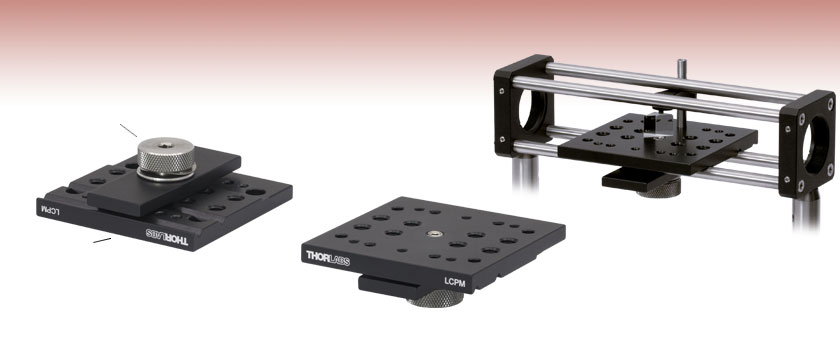
- Prism Mount for 16 mm Cubes
- One Model Compatible with 30 mm and 60 mm Cage Systems
- LCPM Accepts PM3 and PM4 Clamping Arms
Spring-Loaded
Locking Knob
V-Slots for 30 mm and 60 mm Cage Assembly
LCPM
Bottom View
LCPM
Top View
Application Idea
The LCPM Horizontal Platform and the PM3 Clamping Arm Mounted in a 30 mm Cage System

Please Wait
The LCPM(/M) serves as an excellent general-purpose cage system mounting platform. The platform features a generous array of 1/4"-20 (M6), 8-32 (M4), and 6-32 (M4) tapped mounting holes. Clamping arms with 6-32 (M4) and 8-32 (M4) threads are available separately below. The underside of the mounting plate is equipped with two V-slots, providing compatibility for the 30 mm and 60 mm cage system standards. A locking plate actuated by a spring-loaded thumbscrew provides clamping force to the mating cage rods for secure positioning.
Cage System Overview
The Cage Assembly System provides a convenient way to construct large optomechanical systems with an established line of precision-machined building blocks designed for high flexibility and accurate alignment.
16 mm, 30 mm, and 60 mm Cage System Standards
Thorlabs offers three standards defined by the center-to-center spacing of the cage assembly rods (see Figure 14A). The 16 mm cage, 30 mm cage, and 60 mm cage standards are designed to accommodate Ø1/2", Ø1", and Ø2" optics, respectively. Specialized cage plates that allow smaller optics to be directly inserted into our larger cage systems are also available.
Standard Threads
The flexibility of our Cage Assembly System stems from well-defined mounting and thread standards designed to directly interface with a wide range of specialized products. The three most prevalent thread standards are our SM05 Series (0.535"-40 thread), SM1 Series (1.035"-40 thread), and SM2 Series (2.035"-40 thread), all of which were defined to house the industry's most common optic sizes. Essential building blocks, such as our popular lens tubes, directly interface to these standards.

Figure 14A An example of the standard cage plate measurements determining cage system compatibility.
| Standard Cage System Measurements | |||
|---|---|---|---|
| Cage System | 16 mm | 30 mm | 60 mm |
| Thread Series | SM05 | SM1 | SM2 |
| Rod to Rod Spacing | 16 mm (0.63") | 30 mm (1.18") | 60 mm (2.36") |
| Total Length | 25 mm (0.98") | 41 mm (1.60") | 71.1 mm (2.80") |
| Cage Components | ||
|---|---|---|
| Cage Rods | 16 mm | These rods are used to connect cage plates, optic mounts, and other components in the cage system. The SR Series Cage Rods are compatible with our 16 mm cage systems, while the 30 mm and 60 mm cage systems use ER Series Cage Rods. |
| 30 mm | ||
| 60 mm | ||
| Cage Plates | 16 mm | These serve as the basic building blocks for a cage system. They may have SM-threaded central bores, smooth bores sized for industry standard optics or to accommodate the outer profile of our SM Series Lens Tubes, or specialized bores for other components such as our FiberPorts. |
| 30 mm | ||
| 60 mm | ||
| Optic Mounts | 16 mm | Thorlabs offers fixed, kinematic, rotation, and translation mounts specifically designed for our Cage Systems. |
| 30 mm | ||
| 60 mm | ||
| Cage Cubes | 16 mm | These cubes are useful for housing larger optical components, such as prisms or mirrors, or optics that need to sit at an angle to the beam path, such as beamsplitters. Our cage cubes are available empty or with pre-mounted optics. |
| 30 mm | ||
| 60 mm | ||
| Replacement Setscrews | Replacement setscrews are offered for our 16 mm (SS4B013, SS4B025, and SS4B038) and 30 mm (SS4MS5 and SS4MS4) cage systems products. | |
| Post and Breadboard Mounts and Adapters | Mounting options for cage systems can be found on our Cage System Construction pages. Cage Systems can be mounted either parallel or perpendicular to the table surface. | |
| Size Adapters | Cage System Size Adapters can be used to integrate components from different cage system and threading standards. | |
| Specialized Components | Thorlabs also produces specialized cage components, such as Filter Wheels, a HeNe Laser Mount, and a FiberPort Cage Plate Adapter, allowing a wide range of our products to be integrated into cage-mounted optical systems. Explore our Cage Systems Visual Navigation Guide to see the full range of Thorlabs' cage components. | |
| Posted Comments: | |
Ben Garber
(posted 2020-06-26 13:19:33.77) There's a critical dimension missing in the mechanical drawing for the LPCM--what's the height of the surface above the center of the rods? YLohia
(posted 2020-06-26 01:52:50.0) Thank you for contacting Thorlabs. The distance between the center of the cage rods and the top surface of the plate is 8.588 mm. acable
(posted 2007-08-02 12:00:56.0) Main photo is upside down, top view is more important, could have both but a clear image of the top is the one i would want first. |

- Large Mounting Surface
- 1/4"-20 (M6), 8-32 (M4), and 6-32 (M4) Tapped Holes
- Bottom Located Knob for Position Locking
- One Model Fits 30 mm and 60 mm Cage System Standards
- 3/16" (5 mm) Hex for Locking Down

Click for Details
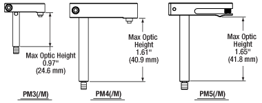
Figure 756A Mechanical Drawings
- Provide Clamping Force for Our Platform Mounts
- Threaded Hole on Top and Threaded Stud on Bottom of Post
- 6-32 Threads on PM3 and PM4
- 8-32 Threads on PM5
- M4 x 0.7 Threads on All Metric Versions
- Maximum Optic Heights from 0.97" to 1.65" (24.6 mm to 41.8 mm)
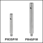
- Extension Posts Available to Increase Max Optic Height
- PM3SP(/M) with PM3(/M): Hold Optics up to 2.21" (56.1 mm) Tall
- PM4SP(/M) with PM4(/M): Hold Optics up to 3.61" (91.7 mm) Tall
Click to Enlarge
Figure 756B Clamping Arm Extension Posts with Metric Indicator Groove
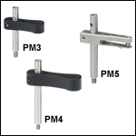
Thorlabs' Clamping Arms provide clamping force to secure optics to our kinematic platform mounts, stages, and V-clamps. The PM3(/M) accommodates optics up to 0.97" tall and features a 0.69" center-to-center distance between the post and the nylon-tipped setscrew that holds the optic. The PM4(/M) accommodates optics up to 1.61" and features a 1.16" center-to-center distance between the post and the nylon-tipped setscrew. The maximum optic height of the PM3(/M) or PM4(/M) Clamping Arms can be extended using our PM3SP(/M) or PM4SP(/M) Extension Posts, respectively. These extension posts are identical to the posts included in each complete clamping arm. Each clamping arm features 6-32 (M4 x 0.7) threads. The PM3 and PM4 can be mounted in 8-32 tapped holes by using the AS6E8E thread adapter, which features internal 6-32 threads and external 8-32 threads. This thread adapter has an outer diameter of 0.24", which is the same as the PM4SP extension post and the post included with the PM4 clamping arm. This allows the clamping arm to be adjusted across the seam between either post and the adapter. The smaller diameters of the included post for the PM3 clamping arm and the PM3SP extension post cause the thread adapter to act as a stop for the clamping arm.
The PM5(/M) clamping arm is made entirely from heat-treated stainless steel, which helps maintain stability in fluctuating temperatures and provides vacuum compatibility. This clamping arm is recommended for use with the POLARIS-K1M4(/M), but it can be used with any platform mount or stage that has one or more 8-32 (M4 x 0.7) tapped holes. The PM5(/M) can hold optics up to 1.65" tall, and the distance from the post center to the contact point that holds the optic is 0.90".
Each clamping arm is attached to its post using a flexure mechanism that locks with a 5/64" (2.0 mm) balldriver or hex key. The setscrew on top of the clamping arm also accepts a 5/64" (2.0 mm) balldriver or hex key in order to clamp down on the optic. The post includes a through hole which can be leveraged for added torque when tightening down the post. Please see Figure 756A for additional information.
 Products Home


 Zoom
Zoom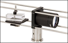
 Platforms