 Products Home / Optomechanical Components / Optomechanical Mounts / Optical Mirror Mounts / Polaris® Mirror Mounts / Side Optic Retention Polaris Mirror Mounts / Polaris®KA Side Retention Mounts for Ø1" Optics
Polaris®KA Side Retention Mounts for Ø1" Optics
- Designed for Long-Term Stability and Minimal Temperature-Dependent Hysteresis
- Matched Actuator and Back Plate Threading Minimize Drift and Backlash
- Lightweight Aluminum Front and Back Plates
- Sapphire Adjuster Seats Prevent Wear Over Time
Application Idea
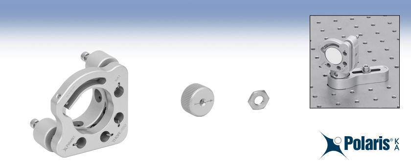
KA1 Ø1" Mirror Mount with Mirror on a Ø1" Post for Polaris Mounts
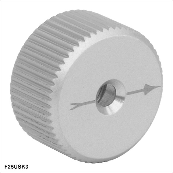
F25USK3
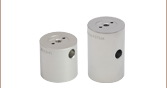
Aluminum Removable Knob for 1/4"-100 Adjusters
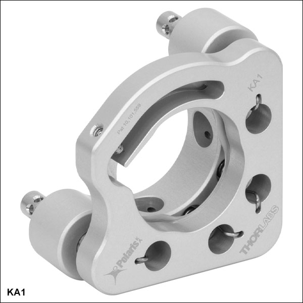
KA1
2 Adjusters with Side Holes
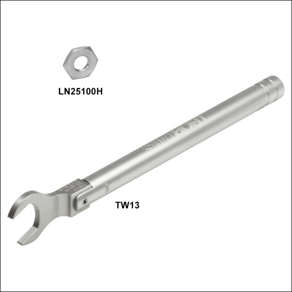
LN25100H
Aluminum 1/4"-100 Lock Nut


Please Wait
Click to Enlarge
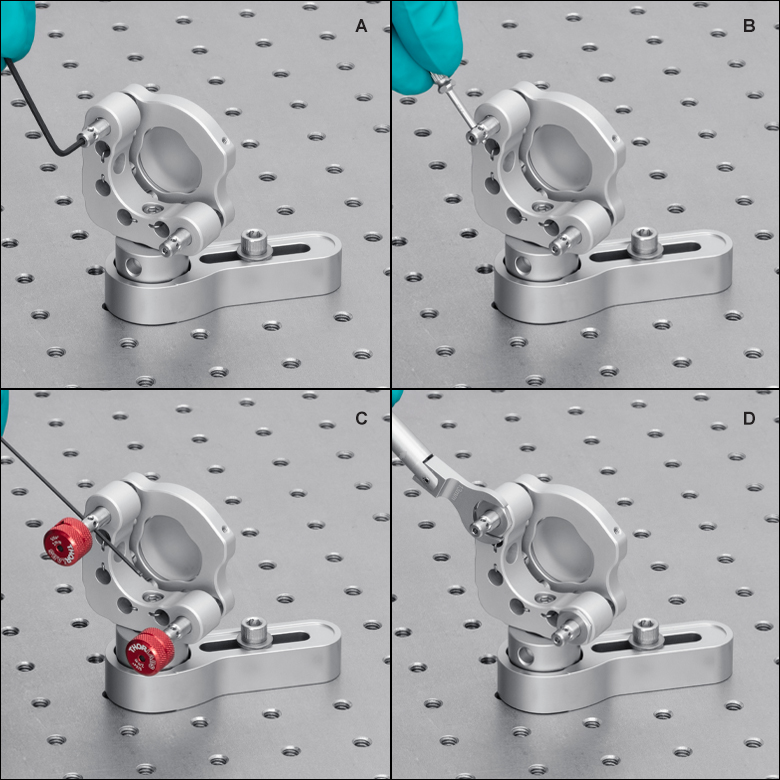
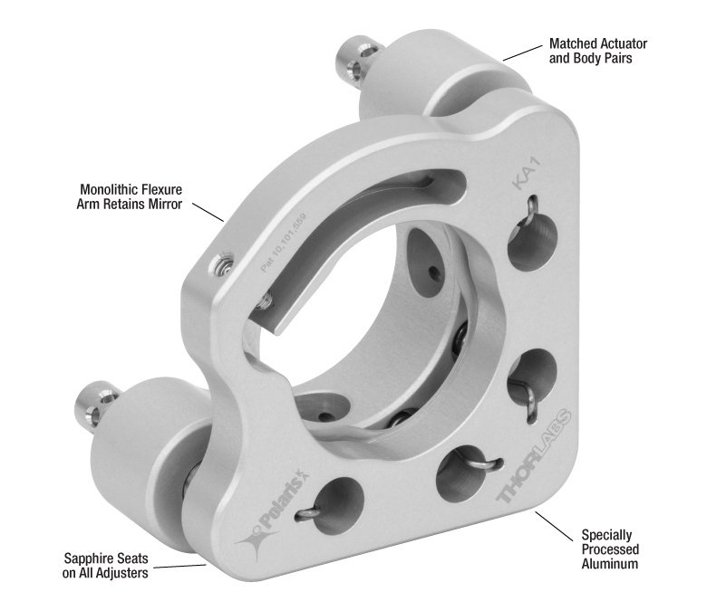
Figure 1.1 Methods of Adjusting the KA1 Ø1" Mount:
A: 5/64" (2.0 mm) Hex Key in the End of the Adjuster
B: SA1 Tool Through Adjuster Side Holes
C: HKTS-5/64 Hex Knobs with 1/16" (1.5 mm) Balldriver Through Side Holes for Fine Adjustment
D: TW13 Torque Wrench Used to Secure LN25100H Lock Nut
| Quick Links |
|---|
| Ø1" Mounts with 2 Adjusters |
| Locking Collar & Spanner Wrench |
| Removable Adjuster Knob |
| Hex Adjusters |
| Side Hole Adjustment Tool |
| Lock Nut & Torque Wrench |
Click to Enlarge
Figure 1.2 Each PolarisKA mount undergoes extensive thermal testing to ensure high-quality performance. Please see the Test Data tab for additional test results.
Features
- Machined from Aged 7075 Aluminum Alloy for Exceptional Tensile Strength, Stiffness, Surface Toughness, and Dimensional Stability
- Hardened Stainless Steel Ball Contacts with Sapphire Seats for Durability and Smooth Movement
- Matched Actuator and Back Plate Provide Stability and Smooth Kinematic Adjustment
- Extensive Testing Guarantees Less than 4 μrad Deviation after 15 °C Temperature Cycling (See Test Data Tab for Details)
- Specialty Anodized Frames and Passivated Stainless Steel Adjusters Designed for Vacuum and High-Power Laser Cavity Applications
- Patented Optic Bore Design with Monolithic Flexure Arm (US Patent 10,101,559)
- Patent Pending Spring Design Reduces Contamination
- Mounting Holes Enable Left-Handed or Right-Handed Operation
- Custom Mount Configurations are Available by Contacting Tech Sales
The Polaris® KA1 Low-Drift Kinematic Mirror Mount features low-drift design considerations and clear-anodized 7075 aluminum construction, making it ideal for industrial applications requiring stringent long-term alignment stability.
Optic Retention
This Ø1" mirror mount features a patented optic bore design with a monolithic flexure arm to secure the optic. This design provides high holding force and pointing stability with minimal optic distortion. For more details, please see the Test Data tab.
Polaris optic bores are precision machined to achieve a fit that will provide optimal beam pointing stability over changing environmental conditions such as temperature changes, transportation shock, and vibration. Performance will be diminished if a Ø1" mount is used with a Ø25 mm optic or an optic with an outer diameter tolerance greater than zero.
Design
Machined from aged, lightweight 7075 aluminum alloy, this PolarisKA mount utilizes precision-matched adjusters with ball contacts and sapphire seats to provide smooth kinematic adjustment. As shown on the Test Data tab, this mount has undergone extensive testing to ensure high-quality performance. The Polaris design addresses all of the common causes of beam misalignment; please refer to the Design Features tab for detailed information.
Post Mounting
The KA1 side retention mount is equipped with #8 (M4) counterbores for post mounting. See the Usage Tips tab for more recommendations about mounting configurations.
Cleanroom and Vacuum Compatibility
All of our Polaris KA mounts are designed to be compatible with cleanroom and vacuum applications and have maximum bake-out and operating temperatures of 80°C. See the Specs tab and the Design Features tab for details.
The aluminum front and back plates of the KA1 mount is acid etched, specialty anodized with a thin 5 µm oxide layer, and duplex sealed with nickel, followed by boiling in reverse osmosis deionized (RODI) water. This process creates an all-metal surface that is clean, smooth, thin, hard, non-porous, and has a sealed oxide layer that supports use in low outgassing laser systems and cleanroom assembled systems. This same surface treatment is also used by some vacuum chamber manufacturers to prevent a native oxide layer from forming on the surface of bare aluminum. This surface finish provides an improvement over standard anodizing. For PolarisKA mounts, we recommend a maximum bake-out temperature of no more than 80 °C. Aluminum has a higher emissivity compared to stainless steel, allowing it to dissipate heat more quickly. For additional details, refer to the Specs tab.
To further reduce outgassing rates in ultra-high vacuum (UHV) systems, we can provide mounts upon request with bare aluminum parts that are only acid etched; please contact Tech Sales with inquiries. Due to the reduction in surface hardness, these mounts will not have the same surface toughness, resulting in faster wear on the lens cells and adjuster screw threads. Such mounts would also need to be carefully handled and stored to prevent surface contamination and the formation of a native oxide layer. These custom mounts would support a maximum bake-out temperature of no more than 200°C.
For the lowest outgassing rates in UHV systems, please consider the stainless steel Polaris line, which support a maximum bake-out temperature of no more than 200°C.
| Item # | KA1 |
|---|---|
| Optic Sizea | Ø1" |
| Optic Thickness (Min) | 0.14" (3.5 mm) |
| Number of Adjusters | Two |
| Adjuster Drive | 5/64" (2.0 mm) Hex, Ø0.07" (1.8 mm) Side Adjustment Holes |
| Adjuster Thread | 1/4"-100 |
| Actuator Matching | Matched Actuator/Body Pairs |
| Measured Point-to-Point Mechanical Resolution per Adjuster |
5 µrad (Typical); 2 µrad (Achievable) |
| Adjustment Resolutionb | ~7.7 mrad/rev |
| Mechanical Angular Range (Nominal) | ±4° |
| Front Plate Separation at Pivot Adjuster (Nominal) | 3.175 mm |
| Front Plate Translation (Max) | N/A |
| Beam Deviationc After Thermal Cycling | <4 μrad |
| Recommended Optic Mounting Torqued | 5 - 7 oz-in for 6 mm Thick UVFS Optics |
| Mounting | Two #8 (M4) Counterbores at 90° |
| Cleaninge | Adjuster screws are passivated per ASTM-967; Frames are acid etched, anodized to MIL-A-8625, Type 2, Class 1, with a thin dense oxide layer and duplex sealed using nickel followed by boiling in reverse osmosis deionized (RODI) water. |
| Vacuum Compatibilityf | 10-9 Torr at 25 °C with Proper Bake Out 10-5 Torr at 25 °C without Bake Out Grease Vapor Pressure: 10-13 Torr at 20 °C; 10-5 Torr at 200 °C Epoxy Meets Low Outgassing Standards NASA ASTM E595, Telcordia GR-1221 |
| Mass (Weight) | 64 g (2.27 oz) |
| Operating Temperature Range | -30 to 80 °C |
Polaris®KA Mirror Mount Test Data
All Polaris Low-Drift Kinematic Mirror Mounts undergo extensive testing to ensure high-quality performance. Thermal shock testing confirms the exceptional stability of the mounts and demonstrates that they reliably return to their initial position after a transient temperature shift. Interferometric wavefront distortion testing demonstrates the ability of Polaris mounts to secure an optic without significantly distorting the optical surface.
Video 3.1 Vibration Testing for Polaris Mounts (Ø19 mm Polaris Mount Shown)
Vibration Testing
Purpose: This testing was done to determine how reliably PolarisKA mirror mounts behave when subjected to intense physical vibrations.
Procedure: A pair of identical KA1 mirror mounts were mounted on Ø1" Posts for Polaris Mirror Mounts and secured to a stainless steel breadboard with POLARIS-CA1 clamping arms. Laser beams were reflected from the mirrors onto two position sensing detectors, located on the same breadboard. The entire platform was vibrated with a variable frequency and amplitude, and the displacement of the beam on the detector was recorded. The two beam paths were oriented at right angles so that the vibrational motion was in a direction parallel to the face of one mount and perpendicular to the face of the other. Please see Video 3.1 for a demonstration of our Polaris vibration test (the mount shown in the video is the POLARIS-K19S4 Ø19 mm mount).
Results: When subjected to vibrational frequencies from 5 to 500 Hz and accelerations as high as 6 g, the KA1 mounts remained mechanically sound. The angular position of the mounts remained stable within about 10 µrad for both parallel and perpendicular vibrations.
Conclusions: Our PolarisKA mirror mounts provide exceptional performance, even under rugged operating conditions. As a result, these mounts are ideal for use in systems that require the greatest degree of stability when vibrational noise is expected.
Positional Repeatability After Thermal Shock
Purpose: This testing was done to determine how reliably the mount returns the mirror, without hysteresis, to its initial position. These measurements show that the alignment of the optical system is unaffected by the temperature shock.
Procedure: After attaching the PolarisKA mount to a Ø1" Post, the mirror and post assembly was secured to a stainless steel optical table in a temperature-controlled environment. The mirror was held using the flexure mechanism; see the Usage Tips tab for additional mounting considerations. A beam from an independently temperature-stabilized laser diode was reflected by the mirror onto a position sensing detector. The temperature of each mirror mount tested was raised to at least 37 °C. The elevated temperature was maintained in order to soak the mount at a constant temperature. Then the temperature of the mirror mount was returned to the starting temperature. The results of these tests are shown in Table 3.2.
Results: As can be seen in these plots, when the mount was returned to its initial temperature, the angular position (both pitch and yaw) of the mirrors returned to within 4 µrad of its initial position. The performance of the mount was tested further by subjecting the mount to repeated temperature change cycles. After each cycle, the mirror's position reliably returned to within 4 µrad of its initial position.
For Comparison: To get a 4 µrad change in the mount’s position, the 1/4"-100 threaded adjuster on the PolarisKA mount needs to be rotated by only 0.2° (1/1800 of a turn). A skilled operator might be able to make an adjustment as small as 0.3° (1/1200 of a turn), which corresponds to a 6 µrad change in the mount's position.
Conclusions: PolarisKA Mirror Mounts are high-quality, ultra-stable mounts that will reliably return a mirror to its original position after cycling through a temperature change. As a result, PolarisKA mounts are ideal for use in applications that require long-term alignment stability.
| Table 3.2 KA1 2-Adjuster Mount with Adjuster Side Holes, Monolithic Optic Retentiond |
|---|
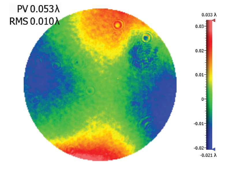
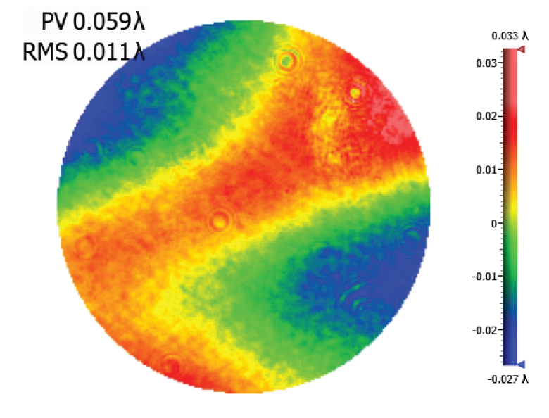
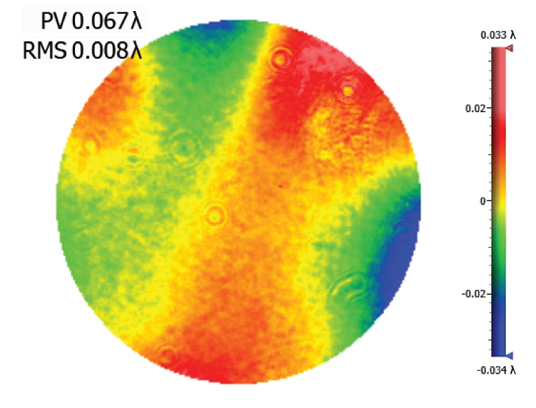
Optical Distortion Testing Using a ZYGO Phase-Shifting Interferometer
Mounting stresses are responsible for the strain that results in optical surface distortion. Minimizing distortion effects is crucial; any distortion to the optic affects the reflected wavefront. The PolarisKA mount sold below features a monolithic flexure arm that is designed to provide maximum stability while minimizing optic distortion.
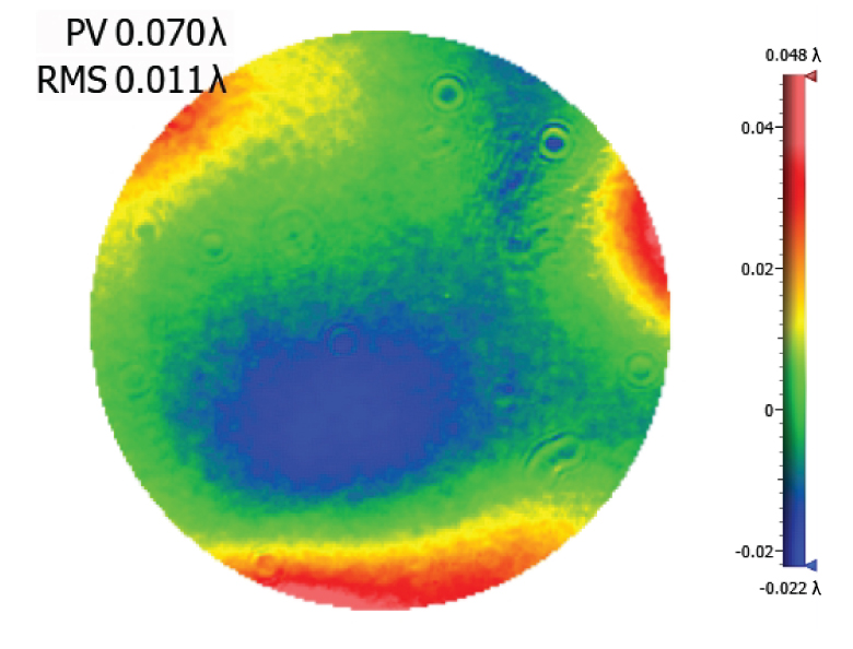
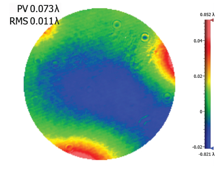
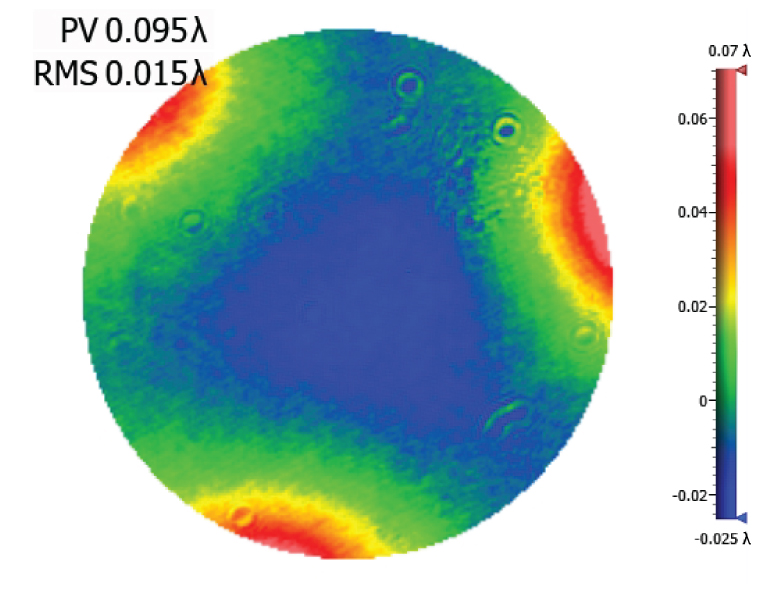
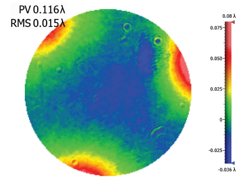
To determine the amount of optic distortion exerted on the mirror by the flexure arm, a ZYGO Phase-Shifting Interferometer with a 633 nm beam was used to measure the wavefront distortion at different torque angles (see screenshots of the Zygo testing runs by clicking on the links in Table 3.6). Based on results of the tests, we recommend turning the setscrew 20 to 40° clockwise after initial contact, at which point the optic wavefront distortion is ≤0.1λ.
Please note that the optimal optic mounting torque can vary due to variations in optic diameter and tolerance buildup.
Procedure:
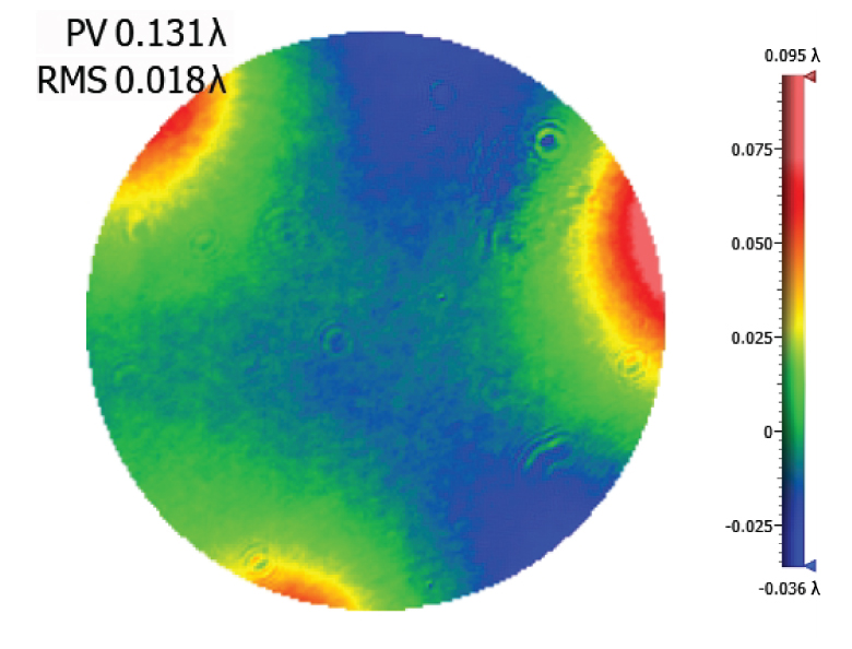
A broadband dielectric mirror was installed into a Polaris mount using the setscrew to clamp down the flexure arm. The setscrew was engaged until the flexure arm initially made contact, then was turned clockwise by a number of degrees. Measurements of the optic distortion were then recorded using the ZYGO interferometer. Once each measurement was complete, the amount of force needed to push the optic out of the mount was measured to check optic retention. The wavefront distortion values shown in the upper left of the screenshots give peak-to-valley distortion across the entire optic, representing the worst-case scenario; the center of the optic exhibits significantly less distortion than the edge.
Results:
As seen in Table 3.6, the peak-to-valley wavefront distortion was found to be ≤0.1λ when the setscrew was turned 20 to 40° clockwise after initial contact. This provides a safety margin to ensure the mount maintains good contact with temperature changes and thermal expansion of the mount.
| Table 3.6 Wavefront Distortion for a Ø1" Mirror in a KA1 Polaris Mount | ||
|---|---|---|
| Torque Anglea |
Wavefront Distortion (Peak-to-Valley)b (Click for Example Zygo Screenshot) |
Push-Out Forcec |
| 10° | 0.047λ | >5 lbf |
| 20° | 0.048λ | |
| 30° | 0.055λ | |
| 40° | 0.057λ | |
| 50° | 0.062λ | |
| 60° | 0.074λ | |
| 70° | 0.086λ | |
| 80° | 0.096λ | |
| 90° | 0.115λ | |
| 100° | 0.132λ | |
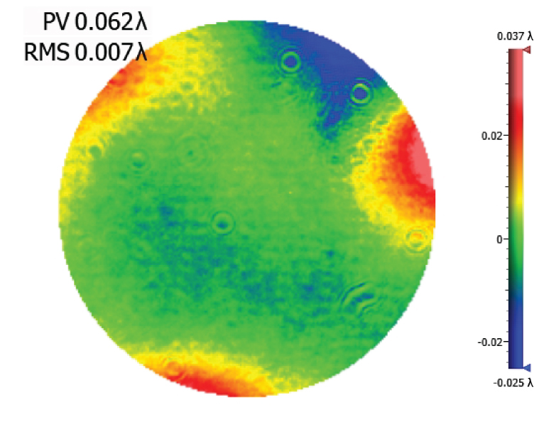
Click to Enlarge
Figure 3.5 KA1 Wavefront Distortion with Setscrew Turned 50° Clockwise After Initial Contact
(See Table 3.6 for Other Setscrew Torques)
Click to Enlarge
Figure 4.1 Design Features of KA1 Side Optic Retention Mount
Several common factors typically lead to beam misalignment in an optical setup. These include temperature-induced hysteresis of the mirror's position, crosstalk, drift, and backlash. Polaris® mirror mounts are designed specifically to minimize these misalignment factors and thus provide extremely stable performance. Hours of extensive research, multiple design efforts using sophisticated design tools, and months of rigorous testing went into choosing the best components to provide an ideal solution for experiments requiring ultra-stable performance from a kinematic mirror mount.
Thermal Hysteresis
The temperature in most labs is not constant due to factors such as air conditioning, the number of people in the room, and the operating states of equipment. Thus, it is necessary that all mounts used in an alignment-sensitive optical setup be designed to minimize any thermally induced alignment effects. All the critical components of the PolarisKA series mirror mounts are made from specially selected dimensionally stable materials, such as low stress aged round 7075 aluminum bar stock to reduce internal stresses that can cause temperature-dependent hysteresis and optimal material tempers to improve the material stiffness and strength. As a result, the alignment of the optical system will be restored when the temperature of the mirror mount is returned to the initial temperature.
The method by which the mirror is secured in the mount is another important design factor for PolarisKA series mounts; these mounts offer excellent performance without the use of adhesives. Instead, the mounts offered on this page use a monolithic flexure arm that is pressed onto the edge of the mirror using a setscrew. Setscrews, when used by themselves to hold an optic, tend to move as the temperature changes. In contrast, the holding force provided by the aluminum flexure arm is sufficient to keep the mirror locked into place regardless of the ambient temperature.
Crosstalk
Crosstalk is minimized by carefully controlling the dimensional tolerances of the front and back plates of the mount so that the pitch and yaw actuators are orthogonal. In addition, sapphire seats are used at all three contact points. Standard metal-to-metal actuator contact points will wear down over time. The polished sapphire seats of PolarisKA series mounts, in conjunction with the hardened stainless steel actuator tips, maintain the integrity of the contact surfaces over time.
Drift and Backlash
In order to minimize the positional drift of the mirror mount and backlash, it is necessary to limit the amount of play in the adjuster as well as the amount of lubricant used. When an adjustment is made to the actuator, the lubricant will be squeezed out of some spaces and built up in others. This non-equilibrium distribution of lubricant will slowly relax back into an equilibrium state. However, in doing so, this may cause the position of the front plate of the mount to move. PolarisKA series mounts use adjusters matched to the body or bushings that exceed all industry standards so very little adjuster lubricant is needed. As a result, alignment of these mounts is extremely stable even after being adjusted (see the Test Data tab for more information). In addition, these adjusters have a smooth feel that allows the user to make small, repeatable adjustments.
Cleanroom and Vacuum Compatibility
The front and back plates of PolarisKA mounts are machined from aged 7075 aluminum alloy for exceptional tensile strength, stiffness, surface toughness, and dimensional stability. They are then acid etched, specialty anodized with a thin 5 µm oxide layer, and duplex sealed with nickel, followed by boiling in reverse osmosis deionized (RODI) water. This process creates an all-metal surface that is clean, smooth, thin, hard, non-porous, and has a sealed oxide layer that supports use in low outgassing laser systems and cleanroom assembled systems. This same surface treatment is also used by some vacuum chamber manufacturers to prevent a native oxide layer from forming on the surface of bare aluminum. This surface finish provides an improvement over standard anodizing. For PolarisKA series mounts, we recommend a maximum bake-out temperature of no more than 80 °C.
To further reduce outgassing rates in ultra-high vacuum (UHV) systems, we can provide mounts upon request with bare aluminum parts that are only acid etched; please contact Tech Sales with inquiries. Due to the reduction in surface hardness, these mounts will not have the same surface toughness as the fully processed mounts, resulting in faster wear on the lens cells and adjuster screw threads. Such mounts would also need to be carefully handled and stored to prevent surface contamination and the formation of a native oxide layer. These custom mounts would support a maximum bake-out temperature of no more than 200 °C.
For the lowest outgassing rates in UHV systems, please consider the stainless steel Polaris products which support a maximum bake-out temperature of no more than 200 °C.
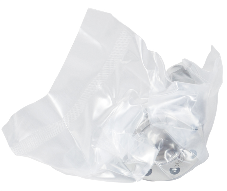
Click to Enlarge
Figure 4.2 All Polaris KA mounts are shipped inside two vacuum bag layers.
The sapphire contacts are bonded into place using a NASA-approved low outgassing procedure. In addition, DuPont LVP High-Vacuum (Krytox) Grease, an ultra-high vacuum compatible, low outgassing PTFE grease, is applied to the adjusters. These features provide high vacuum compatibility and low outgassing performance. When operating at pressures below 10-5 Torr, we highly recommend using an appropriate bake out procedure prior to installing the mount in order to minimize contamination caused by outgassing. Please note that the 8-32 and M4 cap screws included with the Polaris mounts are not rated for pressures below 10-5 Torr.
Cleanroom-Compatible Packaging
Each vacuum-compatible Polaris mount is packaged within two vacuum bag layers after assembly in a clean environment, as seen in Figure 4.2. The vacuum-tight fit of the bags stabilizes the mount, limiting translation of the front plate due to shocks during transportation. The tight fit also minimizes rubbing against the bag, preventing the introduction of bag material shavings that would contaminate the clean mount.
In the vacuum-sealing process, moisture-containing air is drawn out of the packaging. This eliminates unwanted reactions on the surface of the mount without the need for desiccant materials. The vacuum bags protect the mount from contamination by air or dust during transport and storage, and the double-vacuum bag configuration allows for a straightforward and effective cleanroom entry procedure. The outer bag can be removed outside of the cleanroom, allowing the contaminant-free inner bag to be placed into a clean container and transferred into the cleanroom while retaining the benefits of vacuum-bag packaging. Inside the cleanroom, the mount can be removed from the inner bag when ready for use.
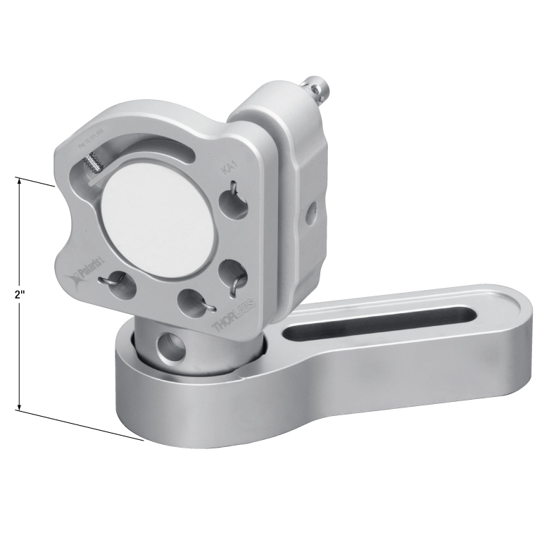
Click to Enlarge
Figure 5.1 These mounts can be mounted to a surface using a Ø1" Post and a clamping arm designed for Polaris mounts. Using a 1" long post, the optical axis is 2" above the table surface.
Through thermal changes and vibrations, Polaris®KA kinematic mirror mounts are designed to provide years of use. Below are some usage tips to ensure that the mount provides optimal performance.
Mounting Guidelines
When installing PolarisKA mounts, we recommend using Ø1" posts and a clamping arm designed for Polaris mounts. If not available, we recommend mounting to aluminum components.
Use a Wide Post
The performance of these mounts is optimized for use with our posts and clamping arms designed for Polaris mounts. These posts are made of stainless steel and provide two lines of contact with the mount, which help confine the bottom of the mount during variations in the surrounding temperature, thereby minimizing potential alignment issues.
Optic Mounting
Since an optic is prone to movement within its mounting bore, all optics should be mounted with the mount out of the setup to ensure accurate mounting that will minimize misalignment effects. We recommend tightening the setscrew past initial contact with the optic to a torque angle of 20° to 40°, as recommended in the Test Data tab. Over torquing the monolithic flexure arm optic retainer past this range can result in a significant increase in the surface distortion of mounted optics (see Figure 5.2).
Click to Enlarge
Figure 5.2 The shaded region in this plot denotes the recommended torque angle for a 6 mm thick optic in a KA1 mount. Over torquing the monolithic flexure arm past the recommended range can result in a significant increase in the surface distortion of mounted optics.
Front Plate’s Position
The mounts sold on this page are designed to allow adjustments of up to 8°. To achieve the best performance, it is recommended that the front plate be kept as parallel as possible to the back plate. This ensures the highest stability of the adjustments.
Mount as Close to the Table’s Surface as Possible
To minimize the impact of vibrations and temperature changes, it is recommended that your setup has as low of a profile as possible. Using short posts will reduce the Y-axis translation caused by temperature variations and will minimize any movements caused by vibrations. The mount can also be secured directly to an optical table or breadboard using a 1/4"-20 to 8-32 thread adapter (Item # AE8E25E) or M6 x 1.0 to M4 x 0.7 thread adapter (Item # AE4M6M). By doing so, the instability introduced by a post will be eliminated. These mounts would perform best when mounted directly to an aluminum base plate.
Polish and Clean the Points of Contact
We highly recommend that the points of contact between the mount and the post, as well as the post and the table, are clean and free of scratches or defects. For best results, we recommend using a polishing stone to clean the table’s surface and an LF1P polishing pad for the top and bottom of the post as well as the bottom of the mount.
Use Polaris-Specific Adjustment Tools
The SA1 Adjustment Tool features a precision fit tip that is designed for the 0.07" side-hole adjusters used in the KA1 mount. Additionally, its handle includes a 5/64" (2.0 mm) hex that is compatible with the hex on the end of each adjuster screw. For the KA1 mount that is exposed to shock and vibration, Thorlabs offers the LN25100H 1/4"-100 Lock Nut. In situations where frequent adjustment is required, the LN25100H lock nut can be hand-tightened with a torque of 4 to 8 oz-in (0.03 to 0.06 N•m). If long-term stability is required, the TW13 Torque Wrench can be used to tighten the lock nuts with 32 oz-in of torque.
Not Recommended
We do not recommend taking the adjusters out of the back plate, as it can contaminate the threading. This can reduce the fine adjustment performance significantly. Also, do not pull the front plate away as it might stretch the springs beyond their operating range or crack the sapphire seats. Finally, do not over tighten the retaining screws that secure the flat spring that holds the optic in place; only slight force is required to secure the optic in place.
| Posted Comments: | |
| No Comments Posted |

 Zoom
Zoom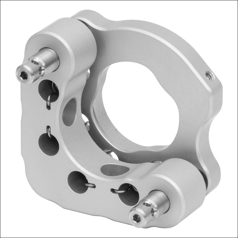
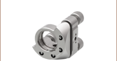
Click to Enlarge
Figure G1.1 KA1 Mount Features 2 Adjusters with Side Holes
- 2 Side-Hole Hex Adjusters
- Designed for use with Ø1" Optics
- 1/4"-100 Threaded Matched Actuator/Body Pairs
- ±4° Mechanical Angular Range (Nominal)
- ~7.7 mrad/rev Resolution
- Less than 4 µrad Deviation after Temperature Cycling (See the Test Data Tab for Details)
- Patented Monolithic Flexure Arm Design for Minimal Optic Distortion and Improved Optic Holding Stability (US Patent 10,101,559, See the Test Data Tab for Detail)
- Patent Pending Spring Design Reduces Contamination
The KA1 2-adjuster Ø1" Polaris Kinematic Mirror Mount is designed to provide easy, high-resolution adjustment and long-term alignment stability. The 2-adjuster design improves mount stability by limiting the available degrees of freedom for movement, making this mount ideal solutions for OEM applications that require reliable operation in rugged environments. A monolithic flexure arm that can be tightened using a 0.05" (1.3 mm) hex key is used to secure an optic in the mount. This optic retention mechanism keeps the wavefront distortion on the mounted optic to a minimum while providing a strong optic retention force (see the Test Data tab for more information).
The KA1 mount has standard-profile hex adjusters with Ø0.07" (Ø1.8 mm) through holes that allow for actuation from the side using our precision-fit SA1 Side Hole Adjustment Tool (sold below) or a 1/16" (1.5 mm) balldriver or hex key. Each adjuster also has a 5/64" (2.0 mm) hex and may be adjusted with the hex on the end of the SA1, our HKTS-5/64 Hex Key Thumbscrews (sold below), or any other 5/64" (2.0 mm) hex wrench. The adjusters on this mount can also be adjusted using the F25USK3 adjuster knob (sold below), or locked using LN25100H lock nuts (sold below). For applications that require frequent tuning of the adjusters, the lock nuts only need to be lightly tightened to a torque of approximately 4 to 8 oz-in (0.03 to 0.06 N·m). For long term stability, we recommend tightening to a torque of 32 oz-in, which can be achieved by using our TW13 preset torque wrench (sold below).
Post mounting is provided by two #8 (M4) counterbores at 90°. We recommend using these mounts with stainless steel Ø1" Posts for Polaris mounts.

 Zoom
Zoom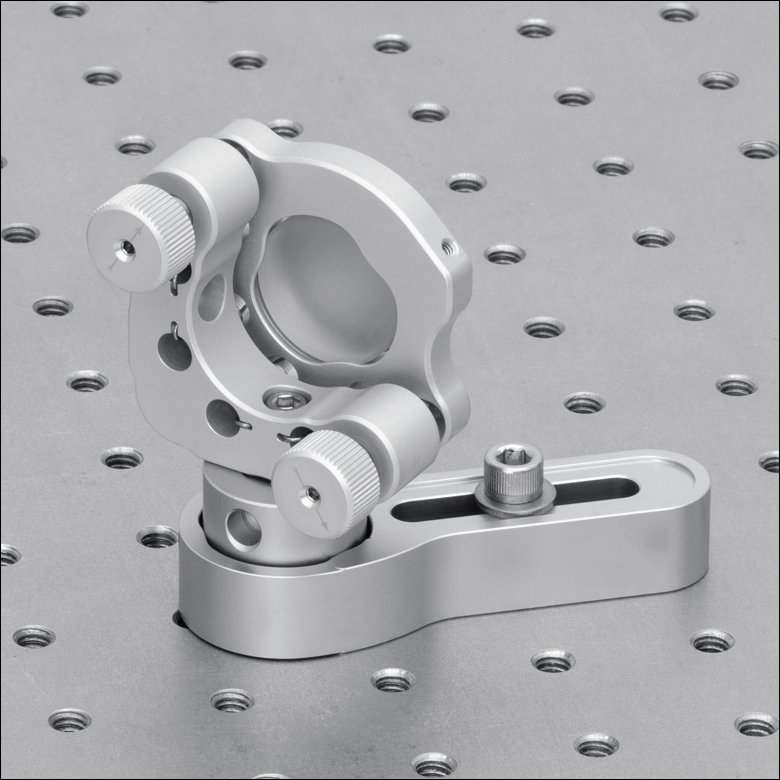
Click to Enlarge
Figure G3.1 KA1 Side Retention Mount with F25USK3 Aluminum Adjusters
- For Convenient Adjustment of 1/4"-100 Adjusters
- Attaches Directly to Adjuster Threading
- Sold Individually
The F25USK3 aluminum removable knob allows the user to turn the 1/4"-100 adjusters by hand. This knob is made out of the same aluminum alloy with the same preparation methods as the KA1 mount (refer to the Specs tab for details). The knob threads directly onto an adjuster and maintains access to the adjuster screw's 5/64" (2 mm) hex socket via a Ø0.10" (2.5 mm) through hole. Note that when the knobs are used with the KA1 mount, they will block the side through holes on the adjuster. The adjuster screw's 5/64" (2 mm) hex socket is still usable when the knobs are attached.

 Zoom
Zoom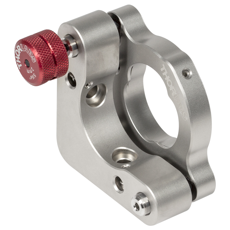
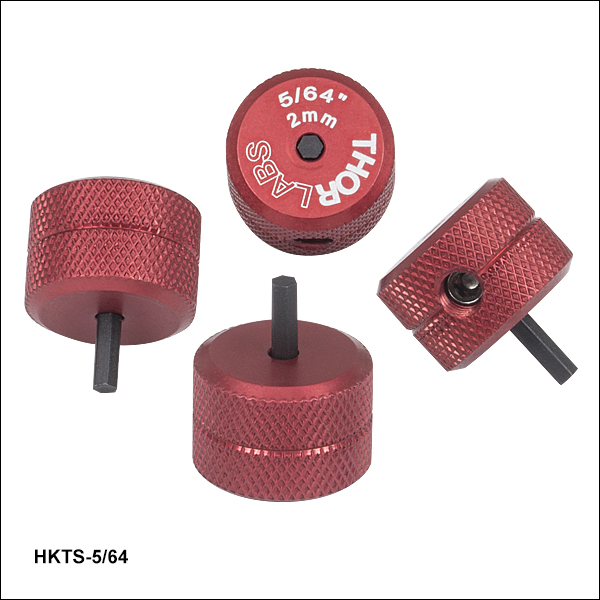
- For Convenient Adjustment of 5/64" and 2 mm Hex-Driven Actuators
- Red Anodized Adjustment Knob with Engraved Hex Size
- Replaceable Hex Tip
- Sold in Packages of 4
These 5/64" Hex Key Adjuster Thumbscrews allow for quick adjustment of many 5/64" and 2 mm hex-driven actuators (or standard actuators with the knobs removed). These temporary knobs can be left in the screw's hex socket between adjustments for convenience (see Figure 206A). An 8-32 setscrew (5/64" hex) secures the replaceable hex bit, which can be reversed if the tip is stripped. Contact Tech Support to order replacement hex key bits.
We offer hex key thumbscrews in sizes from 0.050" to 3/16" and 2 mm to 5 mm.

 Zoom
Zoom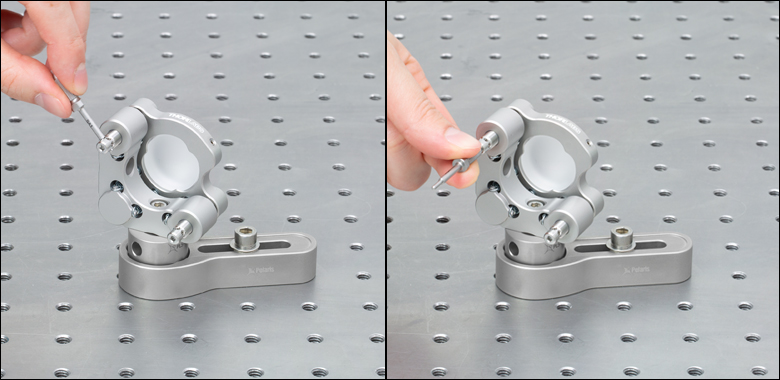
Click to Enlarge
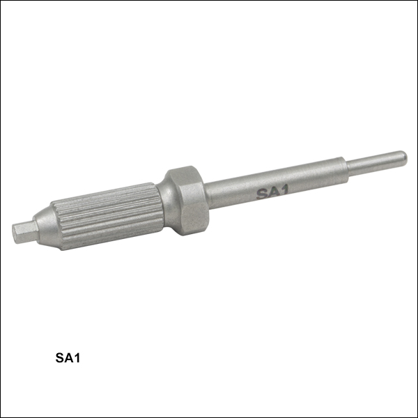
Figure 658A The SA1 tool can be used to adjust a POLARIS-K1S4 mount using the side holes (left) or rear hex (right).
- Ø0.07" Precision-Fit Tip for Side Holes on Polaris Adjusters
- 5/64" (2.0 mm) Hex on Handle
- Magnetic, Chemically Cleaned Stainless Steel
The Side Hole Adjustment Tool features a Ø0.07" precision-fit tip designed for Polaris mounts with side hole adjusters. The handle features a 5/64" (2.0 mm) hex allowing the SA1 to act as a small knob, and the central nut is compatible with a 6.0 mm wrench allowing for a longer lever arm. The precision-fit tip minimizes backlash during adjustments and the depth stop allows the tool to rest securely in a side hole between adjustments. On Ø25 mm mirror mounts and larger, the 1.62" length allows the tool to adjust the actuator 360° without interfering with the other adjuster on the back of the mount.
The SA1 is made of chemically cleaned, hardened, super alloy stainless steel for durability and compatibility with clean environments. The tool is also magnetic allowing it to be easily retrieved from tight or sensitive setups using a magnet.

 Zoom
Zoom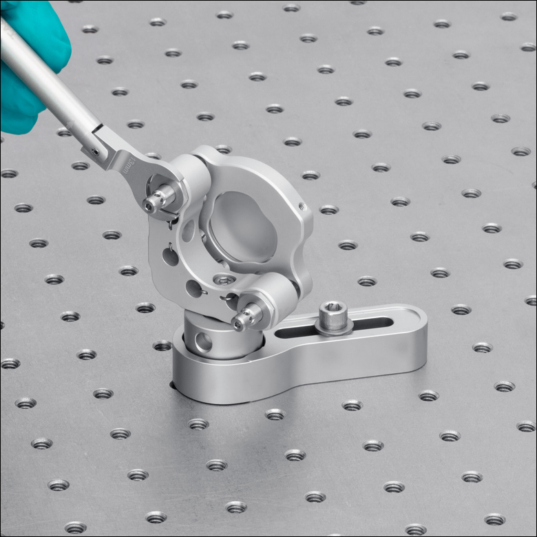
Click to Enlarge
Figure G6.2 TW13 Torque Wrench Used to Secure LN25100H Lock Nut on KA1 Side Retention Mirror Mount
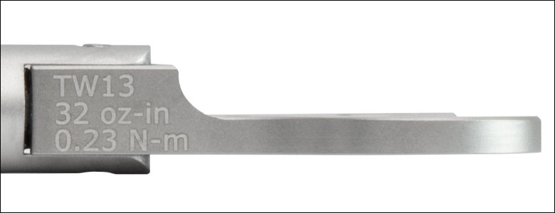
Click to Enlarge
Figure G6.1 The TW13 wrench is engraved with its preset torque value and item #.
- LN25100H 1/4"-100 Aluminum Lock Nut Provides Long Term Adjuster Stability
- TW13 Torque Wrench Ideal for Applications Requiring Long-Term Locking
- Preset Torque Value of 32 oz-in (0.23 N•m)
- Break-Over Design Ensures Proper Torque is Applied
The LN25100H Lock Nut is designed for use with PolarisKA series mounts that have 1/4"-100 adjusters in applications that require long-term adjuster stability or setups that are exposed to shock and vibration; note that the lock nut should not be used with low-profile adjuster mounts. It is made of the same aluminum alloy with the same preparation methods as the KA1 mount (refer to the Specs tab for details).
For applications that require frequent tuning of the adjusters, this lock nut only needs to be lightly tightened by hand to a torque of approximately 4 to 8 oz-in (0.03 to 0.06 N·m). If long term stability is required, the TW13 torque wrench below can be used to apply 32 oz-in (0.17 N·m) of torque to each lock nut. To avoid cross threading the lock nut, place it against the adjuster and "unscrew" the lock nut until you feel a slight drop; then thread the lock nut onto the adjuster.
Preset Torque Wrench
This torque wrench has a preset torque value to secure 13 mm lock nuts on Polaris mounts for long-term locking. When the preset torque value has been achieved, the break-over design will cause the pivoting joint to "break," as shown in Figure G6.2. The wrench's hex head will move back into place once the force is removed. This design prevents further force from being applied to the lock nut. Engraved guidelines indicate the angle the wrench should pivot in order to apply the specified torque; pivoting the handle past these guidelines will over-torque the lock nut. The wrench is also engraved with its preset torque value, torque direction, wrench size, and Item # for easy identification in the field.
This wrench is designed to be compatible with cleanroom and vacuum chamber applications. It is chemically cleaned using the Carpenter AAA passivation method to remove sulfur, iron, and contaminants from the surface. After passivation, it is assembled in a clean environment and double vacuum bagged to eliminate contamination when transported into a cleanroom. Finally, it is bead blasted to minimize reflections when working with setups that include lasers.
Please note that this wrench is not intended for use in applications where adjusters are frequently tuned, as these applications typically require torque values of 4 to 8 oz-in (0.03 to 0.06 N·m).

 Zoom
Zoom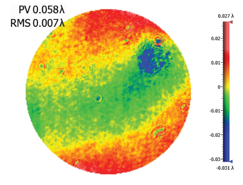
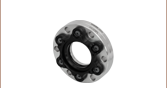
- Provides Long-Term Adjuster Stability
- Compatible with Select Polaris Mounts
- Low Profile: Ø0.33" (Ø8.4 mm) x 0.08" (1.9 mm) Thick
- Tighten Along Rotational Axis Using the POLARIS-T2 Spanner Wrench
This locking collar is compatible with Polaris mounts that have 1/4"-100 adjusters, excluding the piezo-driven mounts and mounts with low-profile adjusters (Item #s POLARIS-K1E3 and POLARIS-K1E2). Designed for long-term adjuster stability or applications that are exposed to shock and vibration, these locking collars are pre-greased with the same ultra-high-vacuum-compatible, low-outgassing PTFE grease as the Polaris mounts and have been tested for adjuster fit.
The POLARIS-T2 spanner wrench has been specifically designed for use in securing the POLARIS-LNS1 locking collar. The double spanner head enables complete engagement while the design allows locking collar adjustments to be along the same line as the adjuster itself. A center through hole allows a 2 mm ball driver to pass through the spanner wrench, so that the adjuster can be held in position while the locking collar is engaged.
For applications that require frequent tuning of the adjusters, the locking collar only needs to be lightly tightened to a torque of approximately 4 to 8 oz-in (0.03 to 0.06 N·m). For long-term stability, we recommend tightening to a torque of 32 oz-in, which can be achieved by using our TW13 preset torque wrench (sold below) in combination with the POLARIS-T2 spanner wrench. To avoid cross threading the locking collar, place it against the adjuster and "unscrew" the collar until you feel a slight drop; then thread the collar onto the adjuster.