 Products Home / Optomechanical Components / Optical Post Assemblies / Ø1" Optical Post Assemblies / Ø1" (Ø25 mm) Posts for Polaris® Mirror Mounts
Ø1" (Ø25 mm) Posts for Polaris® Mirror Mounts

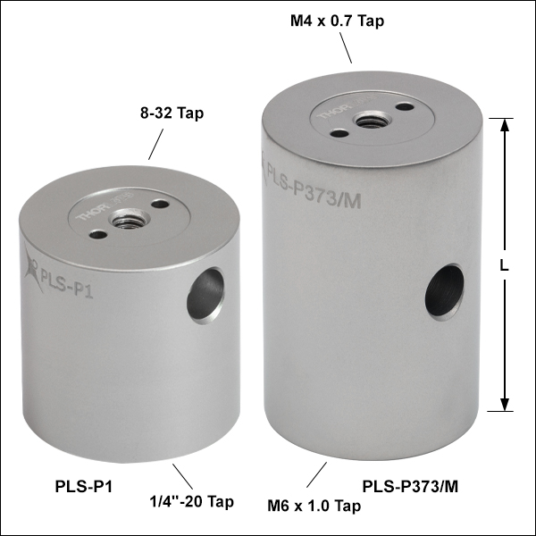
- Top-Located 8-32 (M4 x 0.7) and Bottom-Located 1/4"-20 (M6 x 1.0) Mounting Holes
- Heat-Treated, Stainless Steel Construction
- Precision Ø6 mm Bore for Angle Tuning and Alignment
PLS-P1
One 8-32 Mounting Hole, L = 1.0"
PLS-T2
Three 8-32 Mounting
Holes, L = 2.0"
PLS-P373/M
One M4 Mounting Hole, L = 37.3 mm
L
2.0"
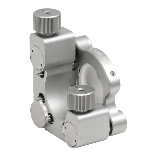
Ø1/2" Polaris Mirror Mount Mounted on a PLS-P150 Post that is Held with a POLARIS-CA1 Clamping Arm
2 mm Alignment Pin Holes on Either Side of Central Mounting Holes


Please Wait
| Vacuum Compatibility Specifications | |
|---|---|
| Vacuum Compatibility as Packageda | >10-9 Torr |
| Materials | 303 Stainless Steel |
| Preparation and Packaging | Chemically Cleaned and Double Vacuum Bagged |
| Stainless Steel Outgassing Rate at 20 °C | 1.8 x 10⁻⁸ Torr-Liters/s/cm2 |

Click to Enlarge
A PLS-P150 Post was mounted at various heights above the work surface using a POLARIS-CA1 Clamping Arm. A force, perpendicular to the post axis, was applied to the post and the overall deflection was measured directly after the force was removed. We recommend mounting posts no more than 6.3 mm (0.25") above the mounting surface when using the POLARIS-CA1 clamping arm. See the Clamping Arms tab for more details on our post deflection test.
Features
- Ø1" or Ø25.0 mm Posts
- Nonmagnetic, Stainless Steel Construction
- One or Three Top-Located 8-32 (M4 x 0.7) Mounting Holes
- One Bottom-Located 1/4"-20 (M6 x 1.0) Mounting Hole
- Two Ø2 mm Alignment Pin Holes on Each End for Precision Mounting (Dowel Pins Not Included)
- Vacuum Compatible to 10-9 Torr at 25 °C as Packaged
- 303 Stainless Steel Heat-Treated to Remove Internal Stresses for Increased System Stability
- Large-Diameter Relief Cut on Top and Bottom for Additional Mounting Stability
- Configurator Available for Custom Lengths and Usage Features
Our Posts for Polaris® Mirror Mounts are machined from heat-treated stainless steel to provide stable support for our Polaris Mirror Mounts. Heat treating the materials removes the internal stresses that can cause temperature-dependent hysteresis. All of our Polaris mirror mounts, clamping arms, and 45° adapters are constructed from this same material, which has a relatively low coefficient of thermal expansion (CTE). Matching the CTE of materials within an optical setup is essential to achieve optimal thermal repeatability.
Each post contains one or three top-located 8-32 (M4 x 0.7) mounting holes and a bottom-located 1/4”-20 (M6 x 1.0) mounting hole. The 8-32 (M4 x 0.7) threads allow a mirror mount to be attached directly to the post, eliminating the need for thread adapters and thereby reducing the instability created when stacking multiple optomechanical components. Please see the Mounting Stability tab for details.
Versions of these posts with a single 8-32 (M4 x 0.7) mounting hole can be used with our smaller Polaris mounts, while the posts with three 8-32 (M4 x 0.7) mounting holes are ideal for securing larger Ø2" and Ø3 Polaris mounts with more than one screw. Popular post lengths are available from stock; custom lengths can be requested using the configurator below (single-mounting-hole versions only) or by contacting Tech Support.
Created with OEM and custom systems in mind, each post features holes for DIN-7m6 ground dowel pins (not included) on either side of the central threaded hole at each end to aid with alignment. Securing posts and accessories within a system using dowel pins prevents them coming loose due to vibrations, shipping, or incidental contact.
Alignment Bore
A Ø6 mm alignment bore is located 20 mm from the base and is drilled towards the vertical center line of the post. Strategically located so that it will not be covered when these posts are secured with a Polaris clamping arm, this bore can be used in combination with our cage rods for the alignment of multiple mounts along a common optical axis or for fine angle tuning.

OEM Solutions and Volume Orders
Thorlabs manufactures custom and high-volume Polaris® products for use in custom and OEM systems. See our custom configurator below for our custom post options. High-volume discounts are built into the configurator, with a minimum order size of 26 posts required to recieve the discount.
For pricing information on high-volume orders of our standard posts, please contact our OEM Sales Team.
Mounting Options
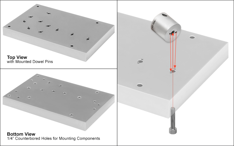
We recommend two methods for securely mounting these posts. The first option, primarily for OEM or custom systems, is to attach the post directly to a custom mounting platform via a counterbored hole for a 1/4"-20 (M6 x 1.0) cap screw and two holes for dowel pins. For details, please see the Custom/OEM Systems tab.
The second recommended option is to use our Polaris clamping arms. Extensive testing has been conducted to show the performance of these posts when they are mounted with a Polaris clamping arm, an example of which is shown in the plot above. For complete details on all of the testing done, please see the Mounting Arm tab.
Cleanroom and Vacuum Compatibility
Our Posts for Polaris mounts are designed to be compatible with cleanroom and vacuum applications. They are chemically cleaned using the Carpenter AAA passivation method to remove sulfur, iron, and contaminants from the surface before being double vacuum bagged. They are compatible directly out of the packaging with vacuum environments down to 10-9 Torr. With additional cleaning and processing, they can be used at even lower pressures, only limited by the outgassing rate of the stainless steel (see the table at the top right). The material properties of the stainless steel and the cleaning methods completed by the end user should be used to determine the appropriateness of these products and materials in a specific vacuum system.
Cleanroom-Compatible Packaging
Each post for Polaris mounts is packaged within two vacuum bag layers after assembly in a clean environment. The vacuum-tight fit minimizes rubbing against the bag, preventing the introduction of bag material shavings that would contaminate the clean post. In the vacuum-sealing process, moisture-containing air is drawn out of the packaging. This eliminates unwanted surface reactions without the need for desiccant materials.
The vacuum bags protect the post from contamination by air or dust during transport and storage, and the double-vacuum bag configuration allows for a straightforward and effective cleanroom entry procedure. The outer bag can be removed outside of the cleanroom, allowing the contaminant-free inner bag to be placed into a clean container and transferred into the cleanroom while retaining the benefits of vacuum-bag packaging. Inside the cleanroom, the inner bag can be removed when the post is ready for use.
Click for Details
Figure 3: With the Polaris® posts, a thread adapter is not needed. An 8-32 (M4 x 0.7) cap screw can be threaded directly into the post. This removes the risk of creating a false mounting surface (see Figure 1) or having partial thread engagement (see Figure 2). Two holes accept dowel pins for additional stability.
Mounting Stability
These posts incorporate one or three top-located 8-32 (M4) mounting holes and a bottom-located 1/4"-20 (M6) mounting hole. Posts with one 8-32 (M4) tap are ideal for use with mounts up to Ø2", while posts with three 8-32 (M4) taps are designed for Ø2" and Ø3" mounts, which have multiple counterbores at each mounting face. These threading choices eliminate the need for a thread adapter, as the mirror mount can be directly attached to the post. Since the addition of a thread adapter can create a false mounting surface (see Figure 1) or a partial thread engagement (see Figure 2), removing the need for one is crucial when stability is of utmost importance.
The addition of alignment pin holes around each mounting hole allows for mounts to be pre-aligned before attachment to the post, as shown in the photo to the right. They also prevent unwanted rotation or movement when securing a mount to the post, during shipping, or when the post is accidentally contacted.
Click to Enlarge
Figure 1: A thread adapter, highlighted in blue above, is shown creating a false mounting surface, which can cause the mounted component to lean to the side and be more vibrationally sensitive.
Click to Enlarge
Figure 2: A thread adapter, highlighted in blue above, is shown reducing the amount of thread engagement between the mounting screw and post mounting hole.
Click for Details
A custom base plate is used to align various Polaris mounts and posts. Click to view the top and bottom of the base plate and how the items were pre-aligned.
Mounting Within a Custom or OEM System
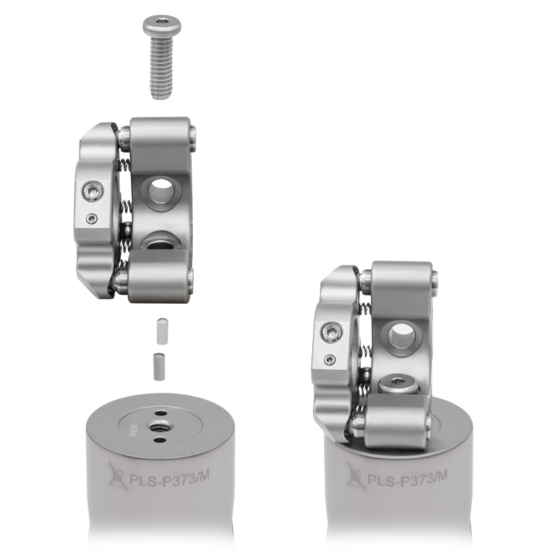
Every standard post designed for a Polaris® mirror mount includes two Ø2 mm alignment pin holes around each mounting hole. When used with dowel pins (not included), these pin holes allow for precision mounting in custom or OEM systems while also preventing mounted components from coming loose due to vibrations, shipping, or incidental contact.
When constructing a custom base plate, the holes for the dowel pins need to be deep enough so that the dowel pin sits at 0.05" ± 0.005" (1.27 mm ± 0.13 mm) above the surface of the base plate. The center-to-center distance between the two dowel pin holes should be 0.394" (10.0 mm), while the center of the 1/4" through hole should be 0.197" (5.0 mm) from the center of each dowel pin hole. The recommended tolerance for the location of the dowel pin holes relative to the mounting hole is ±0.003". Please see the mechanical drawing below for more details.
Click to Enlarge
We recommend that any custom base plate created for our Polaris posts use the above specifications. The drawing provides all center-to-center distances needed with the necessary tolerances. It also shows the ideal distance that the dowel pin (not included) should extrude from the mounting surface.
Polaris® Clamping Arm Testing
Various tests were conducted to show the performance of our Polaris Clamping Arms, the recommended choice to hold posts for Polaris mounts. Many of the results were then compared to other industry-standard products that were put to the same test to show the high-quality performance of the Polaris clamping arms when used with our Ø1" Posts for Polaris Mounts. Click the links below for more information about a specific test.
- Laser Platform Deformation
- Determine the extent to which an industry-standard clamping fork deforms or permanently damages a stainless steel rigid platform, and whether or not the Polaris clamping arm improves upon or prevents this damage.
- Post and Platform Mounting Torque
- Determine the ideal amount of clamping torque necessary to (1) securely mount a Ø1" post within the flexure clamp bore of a Polaris clamping arm and (2) to secure the clamping arm into a laser system. This data was then compared to the closest competitor's industry-standard clamping fork design.
- Post Breaking Torque
- Determine the amount of torque needed to break a Ø1" PLS-P150 post loose from a Polaris clamping arm that was holding it.
- Post Deflection
- Determine how much a Polaris post will temporarily and permanently deflect when it is mounted within a Polaris clamping arm and a force is applied.
Click to Enlarge
Figure 1: Industry-Standard Clamping Fork Beam Drift
Laser Platform Deformation
Purpose: This testing was performed to determine the extent to which an industry-standard clamping fork deforms or permanently damages a stainless steel rigid platform and whether or not the Polaris clamping arm improves upon or prevents this damage. The POLARIS-CA1 clamping arm was used for this test; similar results can be expected for all other Polaris clamping arms. These measurements show that the Polaris clamping arm significantly reduces temporary deformation to the surface and that no permanent damage was measured during our extensive tests.
Procedure: An industry-standard clamping fork was mounted in close proximity to another optical element that was used for aligning a beam onto a position detector. As the clamping fork was mounted to the platform at various torque values (blue data sets in Figure 1 and Figure 2), the yaw and pitch deviation of the beam was measured at the detector. At 75 in-lbs of torque, the fork was left attached to the platform for 16 hours. After the 16 hour period, the fork was released from the table and the final beam deviation was recorded (red data sets in Figure 1 and Figure 2). This procedure was repeated for the POLARIS-CA1 clamping arm. Each test was performed at different regions of the platform. A final deviation of anything but zero indicated that the surface had been permanently deformed.
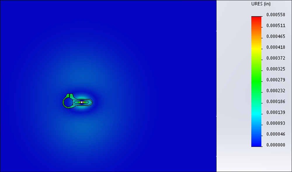
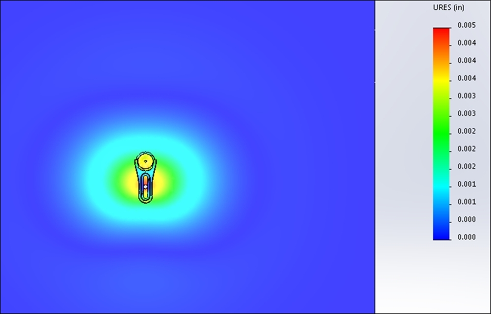
Results: As can be seen in the plots below and to the right, the industry-standard clamping fork created a yaw and pitch deviation of 131 µrad and 702 µrad, respectively, at 75 in-lbs, while the POLARIS-CA1 clamping arm created a yaw and pitch deviation of 12.2 µrad and 61 µrad, respectively, at 75 in-lbs. The POLARIS-CA1 also returned the beam to its initial position when released after a 16 hour hold. The industry-standard clamping fork did not return the beam to its original position; the beam stayed at a yaw and pitch deviation of 176 µrad and 321 µrad, respectively. The simulaton results shown in Figures 3 and 4 show the amount of deformation created by an industry-standard clamping fork compared to the POLARIS-CA1 clamping arm.
Conclusion: The POLARIS-CA1 clamping arm caused no permanent damage to the optical mounting surface and it significantly minimized the deformation to the platform surface when it was in use (see Figures 3 and 4). The industry-standard clamping fork was shown to permanently damage the laser platform after use, and to create severe deformation to the surface while in use. As a result, the Polaris clamping arm is ideal for use in systems requiring long term stability and consistent, precision alignments.
Click for Details
Figure 2: Note that the distortion caused by the Polaris clamping arm at 75 in-lb is comparable to the distortion caused by the industry-standard clamping fork at 10 in-lb.
Click to Enlarge
Figure 4: In comparison, the POLARIS-CA1 clamping arm causes minimal deformations around the fork. Note that the scale on this second plot has been magnified by 10X in order to make these minimal deformations visible.
Click to Enlarge
Figure 3: The industry-standard clamping fork causes large deformations over a significant area surrounding the fork.
Mounting Torque
Purpose: This testing was performed to determine the ideal amount of clamping torque necessary to (1) securely mount a Ø1" post within the flexure clamp bore of a Polaris clamping arm and (2) to secure the clamping arm into a laser system. This data was then compared to the closest competitor's industry-standard clamping fork design.
Procedure: The POLARIS-CA1(/M) was used to hold a standard Ø1" post. The clamping arm was first bolted to a stainless steel rigid platform, and the 1/4"-20 (M6 x 1.0) screw that controls the flexure clamp was actuated to specific torque values. At each torque value, the post had a rotational torque applied around its axis until it moved within the clamping arm's bore. The torque value at the moment directly before this "movement point" is called the holding torque (see plots below). Using similar methods, a mounting slot test was performed to find the ideal torque needed to secure the clamping arm to the laser platform. The mounting slot test was repeated for the POLARIS-SCA1 to determine if the slot size affects the torque measurements.
Results Summary: For optimal performance, the flexure clamping screw of an imperial clamping arm should be tightened with 15 to 25 in-lb of torque and the flexure clamping screw of a metric clamping arm with 1.75 to 3 N•m of torque. When mounting to a table or platform, we recommend using 40 to 65 in-lb of torque for an imperial clamping arm and 4.75 to 7 N•m of torque for a metric clamping arm. Please see below for the detailed results.
Conclusion: The Polaris clamping arm was shown to be the ideal solution for securely mounting a component to a laser system platform. At only 20 in-lb and 40 in-lb of clamping torque for the flexure clamp and mounting slot respectively, a post mounted in an imperial clamping arm can withstand up to 110 in-lb of opposing torque (corresponding torques for a metric clamping arm is 2.4, 4.8, and 12.4 N•m, respectively). This performance is superior to the closest competitor's industry-standard clamping fork, which needs a clamping torque of 70 in-lb in the close position to reach a similar value of 100 in-lb. As demonstrated in the Laser Platform Deformation test above, minimizing the amount of torque applied to the mounting surface prevents permanent damage.
Test 1 Results: Flexure Clamp Holding Torque
As can be seen in Figure 6 below, at 20 in-lbs of clamping torque, the POLARIS-CA1 provided 110 in-lb of holding torque. For reference, 110 in-lbs of torque is enough to damage the threading on a 1/4"-20 stainless steel cap screw. The corresponding torque for the POLARIS-CA1/M is a holding torque of 12.4 N•m at a clamping torque of 2.4 N•m. The torque values for imperial and metric clamps are not a direct conversion due to an efficiency difference between 1/4"-20 and M6 x 1.0 screws. The efficiency of M6 screws is about 5% less than that of 1/4"-20 screws due to differences in diameter and pitch. All imperial Polaris clamping arms will perform similarly to the POLARIS-CA1, while all metric Polaris clamping arms will perform similarly to the POLARIS-CA1/M.
Click to Enlarge
Click for POLARIS-CA1/M Flexure Clamp Holding Torque Results
Figure 6: Results from Test 1. The blue shaded region indicates the recommended flexure clamp torque. All imperial Polaris clamping arms will perform similarly to the POLARIS-CA1, while all metric Polaris clamping arms will perform similarly to the POLARIS-CA1/M.
Click to Enlarge
Figure 5: Holding torque is measured at the moment directly before the "movement point" of the post being torqued.
Test 2 Results: Mounting Slot Holding Torque
The recommended torque for the mounting slot varies depending on the position of the 1/4"-20 (M6 x 1.0) cap screw within the slot (i.e. close to the post, midway along the slot, or far from the post). Figure 8 compares the slot holding torque of the POLARIS-SCA1 and POLARIS-CA1, and shows that the slot size does not affect the torque measurements. The recommended slot holding torque is 40 - 65 in-lb for imperial clamping arms, while for metric clamping arms the slot holding torque is 4.75 - 7 N•m. Similar to the Test 1 results, the torque values for imperial and metric clamps are not a direct conversion due to an efficiency difference between 1/4"-20 and M6 screws. The efficiency of M6 screws is about 5% less than that of 1/4"-20 screws due to differences in diameter and pitch.
The performance of the closest competitor's clamping fork also depends on the position of the 1/4"-20 (M6 x 1.0) cap screw in the slot. However, as shown in Firgure 9, the performance of the fork degrades sharply at the mid and far positions. At the far position, the best holding torque achieved is 32 in-lb with a clamping torque of 70 in-lb. As shown in Figure 10, at 40 in-lbs of clamping torque, the POLARIS-CA1 provided 110 in-lb of holding torque, while at the same clamping torque, the competitor's fork only achieved a holding torque of 38 in-lbs.
Click to Enlarge
Click for POLARIS-CA1/M Slot Holding Torque Results
Figure 8: Results from Test 2. The red shaded region indicates the recommended torque to secure the clamping arm to the optical table. This comparison between the POLARIS-SCA1 and POLARIS-CA1 shows that the slot size does not affect the slot holding torque. All imperial Polaris clamping arms will perform similarly to the POLARIS-CA1, while all metric Polaris clamping arms will perform similarly to the POLARIS-CA1/M.
Click to Enlarge
Figure 7: Holding torque is measured at the moment directly before the "movement point" of the clamping arm being torqued.
Click to Enlarge
Figure 9: Results from Test 2 on a competitor's clamping fork. See Figure 8 for results from POLARIS-CA1(/M).

Click to Enlarge
Figure 10: Comparison of Test 2 results for POLARIS-CA1 and a competitor's clamping fork, both at the middle position in the moutning slot.
Click to Enlarge
Figure 12: Breaking force recorded with the post mounted at 14 different heights above the platform. This shows that upwards of 110 in-lb of torque is required to loosen the PLS-P150 post from the clamping arm when the post is in contact with the work surface.
Click to Enlarge
Figure 11: Breaking torque is defined as the moment directly after the "movement point" of the post being torqued.
Breaking Torque
Purpose: This test was performed to determine the amount of torque needed to break a Ø1" PLS-P150 post loose from a Polaris clamping arm. The POLARIS-CA1 clamping arm was used for this test; similar results can be expected for all other Polaris clamping arms.
This test was repeated at various heights above the work surface.
Procedure: A PLS-P150 1.5" long, Ø1" post was secured with 25 in-lb of torque at various heights within a POLARIS-CA1 clamping arm, which was then secured to a custom laser platform. As shown in Figure 11, torque was then applied to the post axis until it reached its "movement point." This torque was recorded as the breaking torque.
Results: As can be seen in Figure 12, upwards of 110 N•m of torque is required to loosen the PLS-P150 post from the clamping arm. When the post was raised off of the platform by 13 mm, a torque of about 40 N•m was still required to loosen the post. It is important to note here that the clamping arm is only 15.2 mm (0.60") thick.
Conclusion: The PLS-P150 post and clamping arm create an extremely stable system that is resistant to large forces acting upon it, even when the post is raised off of the platform by 13 mm. This is ideal for any custom or OEM system that requires components to stay aligned when faced with vibrations caused by shipping and installation.
Post Deflection
Click to Enlarge
Figure 13: A force was applied to the PLS-P150 post 0.90" (22.9 mm) above the edge of the clamping arm with the post mounted at nine different heights off of the mounting surface. At each mounting height, the post deflection was measured during and after the application of the force.
Purpose: This test was performed to determine the amount of temporary and permanent deflection of a Ø1" post for Polaris mirror mounts secured in a Polaris clamping arm when a force is applied. The POLARIS-CA1 clamping arm was used for this test; similar results can be expected for all other Polaris clamping arms.
Procedure: A PLS-P150 1.5" long, Ø1" post was secured with 25 in-lb of torque at various heights within a POLARIS-CA1 clamping arm, which was then secured to a custom laser platform. A force was then applied to the center of the post, 0.90" (22.9 mm) above the top edge of the clamping arm (see Figure 13 for details). This test was conducted with the post mounted at nine different heights off of the platform, ranging from 0 mm to 8 mm. The amount of deflection was measured while the force was being applied (Figure 14) and after the force was removed (Figure 15).
Results: Figure 14 shows that the PLS-P150 post will deflect by <0.01 mm as a force of ≤40 N is applied for any post height ≤8 mm, and by <0.17 mm as a force of ≤133 N is applied for any post height ≤8 mm. These values show the temporary deflection of the post while the force is being applied. For all of the post mounting heights tested (0 to 8 mm), an applied force ≤35 N caused a permanent deflection of the post smaller than 0.005 mm, measured after the force was removed. For the two lowest mounting heights, 0 and 2 mm, no permanent deflection was measured for applied forces of 45 N or less. At 133 N, the maximum force applied, permanent deflection for all tested mounting heights remained below 0.07 mm.
Conclusion: Our Ø1" posts and POLARIS-CA1 clamping arm create an extremly stable system that is able to resist large forces acting upon it. This is ideal for any custom or OEM system that requires components to stay aligned when faced with vibrations caused by shipping and installation.
Click to Enlarge
Figure 15: Post deflection measured after the applied force was removed. The measurement was repeated with the bottom of the post positioned 0 to 8 mm above of the mounting surface (see the Procedure section for details). For post-to-mounting-surface distances of 2 mm or less, no permanent deflection was measured if the force was ≤45 N.
Click to Enlarge
Figure 14: Post deflection measured while a force was applied to the post. The measurement was repeated with the bottom of the post positioned 0 to 8 mm above of the mounting surface (see the Procedure section for details).
| Posted Comments: | |
Emily Qin
(posted 2019-06-11 11:23:56.273) please add compatible location pins for this family.
thanks llamb
(posted 2019-06-14 12:30:22.0) Thank you for your feedback. We will look into adding compatible dowel pins further. cbrideau
(posted 2017-03-08 17:37:47.157) What are the specifications for the dowel pins for using them with Polaris mirror mounts? I see they are 2mm dia, but what length is best? jlow
(posted 2017-03-09 09:04:02.0) Response from Jeremy at Thorlabs: The recommended length is 5mm. |
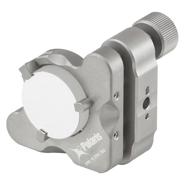
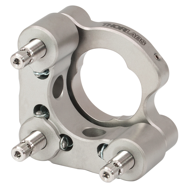
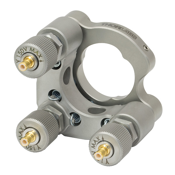
Thorlabs offers several different general varieties of Polaris mounts, including kinematic side optic retention, SM-threaded, low optic distortion, piezo-actuated, vertical drive, and glue-in optic mounts, a fixed monolithic mirror mount and fixed optic mounts, XY translation mounts, 5-axis kinematic mount, and a kinematic platform mount. Refer to the tables below for our complete line of Polaris mounts, grouped by mount type, optic bore size, and then arranged by optic retention method and adjuster type (or intended application in the case of fixed mounts). We also offer a line of accessories that have been specifically designed for use with our Polaris mounts; these are listed in the table to the lower right. Note that the tables below list Item # suffixes that omit the "POLARIS" prefix for brevity. Click the photos below for details.
| Polaris Mount Optic Retention Methods | |||
|---|---|---|---|
| Side Lock | SM Threaded | Low Distortion | Glue-In |
 |
 |
 |
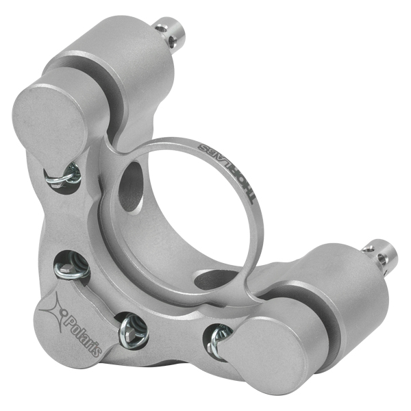 |
| Polaris Mount Adjuster Types | |||||
|---|---|---|---|---|---|
| Side Hole | Hex | Adjuster Knobs | Adjuster Lock Nuts |
Piezo Adjusters | Vertical-Drive Adjusters |
 |
 |
 |
 |
 |
 |
| Polaris Kinematic Mounts for Round Optics | ||||
|---|---|---|---|---|
| Optic Retention Method | Side Lock | SM Threaded | Low Distortion | Glue-In |
| Ø1/2" Optics | ||||
| 2 Side Hole Adjusters | - | - | - | -K05C4 -K05G4 |
| 2 Hex Adjusters | -K05S1 | -K05T1 | -K05F1 | - |
| 2 Adjusters with Lock Nuts | -K05S2 | -K05T2 | -K05F2 | - |
| 2 Piezoelectric Adjusters | -K05P2 | - | - | - |
| 2 Vertical Adjusters | -K05VS2 -K05VS2L |
- | - | - |
| 3 Hex Adjusters | -K05 | - | - | - |
| 3 Adjusters with Lock Nuts | - | -K05T6 | -K05F6 | - |
| 3 Adjuster Knobs (Tip/Tilt/Z) & 2 Hex Adjusters (X/Y) |
- | -K05XY | - | - |
| Ø19 mm (3/4") Optics | ||||
| 2 Side Hole Adjusters | -K19S4 | - | -K19F4/M | -K19G4 |
| Ø25 mm Optics | ||||
| 2 Side Hole Adjusters | -K25S4/M | - | -K25F4/M | - |
| Ø1" Optics | ||||
| 2 Side Hole Adjusters | -K1S4 | - | - | -K1C4 -K1G4 |
| 2 Hex Adjusters | -K1E2 -K1-2AH |
-K1T2 | -K1F2 | - |
| 2 Adjuster Knobs | - | -K1T1 | -K1F1 | - |
| 2 Piezoelectric Adjusters | -K1S2P | - | - | - |
| 2 Vertical Adjusters | -K1VS2 -K1VS2L |
- | - | - |
| 3 Side Hole Adjuster | -K1S5 | - | - | - |
| 3 Hex Adjusters | -K1E3 -K1-H |
-K1T3 | - | - |
| 3 Adjuster Knobs | -K1E -K1 |
-K1T | -K1F | - |
| 3 Piezoelectric Adjusters | -K1S3P | - | - | - |
| 3 Adjuster Knobs (Tip/Tilt/Z) & 2 Hex Adjusters (X/Y) |
- | -K1XY | - | - |
| Optic Retention Method | Side Lock | SM Threaded | Low Distortion | Glue-In |
| Ø1.5" Optics | ||||
| 2 Side Hole Adjusters | -K15S4 | - | -K15F4 | - |
| 2 Vertical Adjusters | -K15VS2 -K15VS2L |
- | - | - |
| 3 Adjuster Knobs (Tip/Tilt/Z) & 2 Hex Adjusters (X/Y) |
- | -K15XY | - | - |
| Ø50 mm Optics | ||||
| 2 Side Hole Adjusters | -K50S4/M | - | -K50F4/M | - |
| Ø2" Optics | ||||
| 2 Hex Adjusters | -K2S2 | -K2T2 | -K2F2 | - |
| 2 Adjuster Knobs | -K2S1 | -K2T1 | -K2F1 | - |
| 2 Piezoelectric Adjusters | -K2S2P | - | - | - |
| 2 Vertical Adjusters | -K2VS2 -K2VS2L |
- | - | - |
| 3 Hex Adjusters | -K2S3 | -K2T3 | -K2F3 | - |
| 3 Adjuster Knobs | -K2 | -K2T | -K2F | - |
| Ø3" Optics | ||||
| 2 Side Hole Adjusters | -K3S4 | - | - | - |
| 3 Side Hole Adjusters | -K3S5 | - | - | - |
| Ø4" Optics | ||||
| 2 Side Hole Adjusters | - | - | -K4F4 | - |
| Ø6" Optics | ||||
| 2 Side Hole Adjusters | - | - | -K6F4 | - |
| Polaris XY Translation Mounts for Round Optics | ||
|---|---|---|
| Optic Retention Method | SM Threaded | Representative Photos |
| Ø1/2" Optics |   |
|
| 2 Hex Adjusters (X/Y) | -05XY | |
| 3 Adjuster Knobs (Tip/Tilt/Z) & 2 Hex Adjusters (X/Y) |
-K05XY | |
| Ø1" Optics | ||
| 2 Hex Adjusters (X/Y) | -1XY | |
| 3 Adjuster Knobs (Tip/Tilt/Z) & 2 Hex Adjusters (X/Y) |
-K1XY | |
| Ø1.5" Optics | ||
| 2 Hex Adjusters (X/Y) & 3 Adjuster Knobs (Tip/Tilt/Z) |
-K15XY | |
| Polaris Fixed Mounts for Round Optics | ||||||
|---|---|---|---|---|---|---|
| Optic Retention Method | Side Lock | Low Distortion |
Glue-In | Representative Photos |
||
| Ø1/2" Optics |   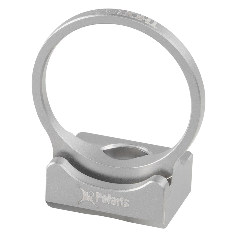  |
|||||
| Optimized for Mirrors | - | -B05F | -C05G | |||
| Optimized for Beamsplitters | -B05S | - | -B05G | |||
| Optimized for Lenses | - | - | -L05G | |||
| Ø19 mm (Ø3/4") Optics | ||||||
| Optimized for Mirrors | -19S50/M | - | - | |||
| Ø1" Optics | ||||||
| Optimized for Mirrors | - | -B1F | -C1G | |||
| Optimized for Beamsplitters | -B1S | - | -B1G | |||
| Optimized for Lenses | - | - | -L1G | |||
| Ø2" Optics | ||||||
| Optimized for Mirrors | - | -B2F | -C2G | |||
| Optimized for Beamsplitters | -B2S | - | - | |||
| Polaris Kinematic 1.8" x 1.8" Platform Mount | ||
|---|---|---|
| Optomech Retention Method | Tapped Holes & Counterbores |
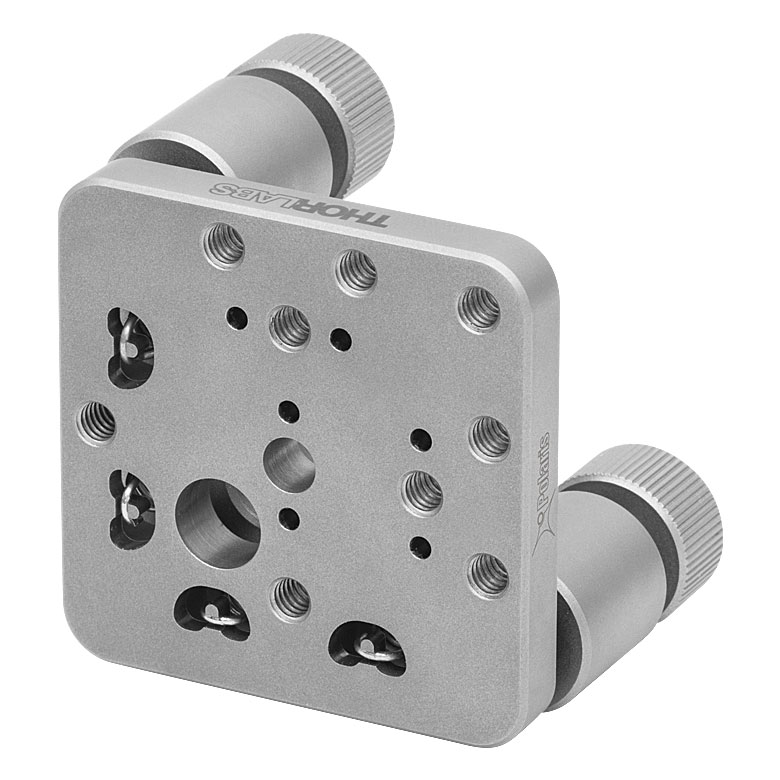 |
| 2 Adjuster Knobs | -K1M4(/M) | |
| Accessories for Polaris Mounts | |
|---|---|
| Description | Representative Photos |
| Ø1" Posts for Polaris Mounts | 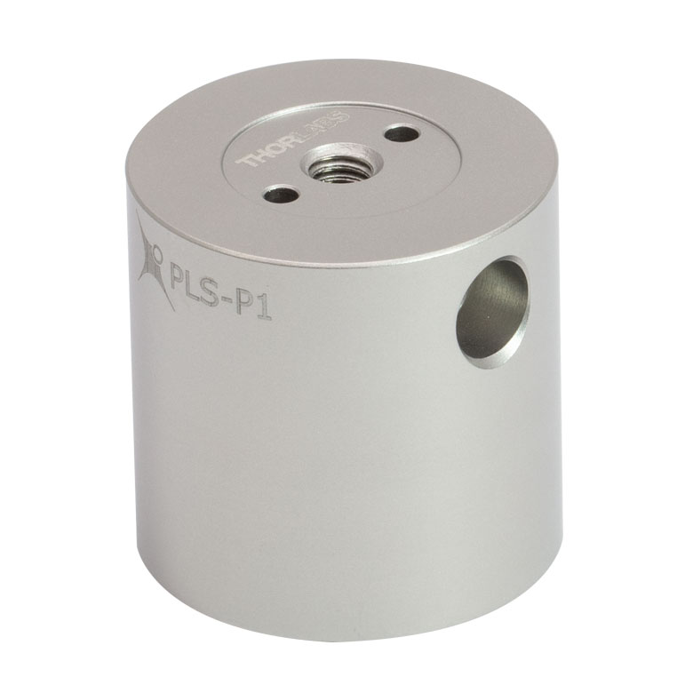 |
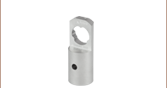
| Polaris Non-Bridging Clamping Arms | 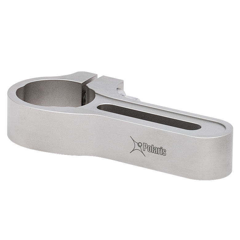 |
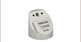
| Polaris 45° Mounting Adapter |  |
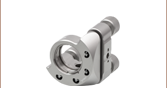
 Posts for Polaris<sup>®</sup> Mirror Mounts, One Mounting Hole")
 Zoom
ZoomClick for Details
Directly attach a Polaris mount via a top-located 8-32 (M4) mounting hole without the need for a thread adapter. Dowel pins (not included) provide precision mounting.
- Designed to Mount Polaris Mounts Up to Ø2"
- One Top-Located 8-32 (M4 x 0.7) Mounting Hole
- One Bottom-Located 1/4"-20 (M6 x 1.0) Mounting Hole
- Two Ø2 mm Alignment Pin Holes Around Each Mounting Hole for Precision Mounting (Dowel Pins Not Included)
These posts feature one top-located 8-32 (M4 x 0.7) mounting hole and one bottom-located 1/4"-20 (M6 x 1.0) mounting hole. They are designed to mount Polaris mirror mounts up to Ø2"; see the table below for the resulting optic axis heights when used with each mount size. Each end of the post has two Ø2 mm alignment pin holes, which are located on either side of the mounting hole. Dowel pins are not included.
A Ø6 mm alignment bore is located 20 mm from the base and can be used in combination with our cage rods for the alignment of multiple mounts along a common optical axis or for fine angle tuning. Note that the alignment bore does not go completely through the PLS-P1 and PLS-P246/M posts. Instead, these posts contain two bores on opposite sides, within ±0.3°, that are 0.20" (5.1 mm) deep. Given their shorter length, a through bore would interfere with the mounting threads and prevent components from being securely attached to the post. In the custom post configurator below, any post with a length of 1.49" (37.6 mm for metric posts) or less will have a similar alignment bore configuration.
| Polaris® Mount and Post Interoperabilitya | |||||||
|---|---|---|---|---|---|---|---|
| Item # | Post Length (L) |
Resulting Optical Axis Height (Optic Center) | |||||
| Ø1/2" Mountsb |
POLARIS-K05P2 Ø1/2" Mount |
Kinematic |
Ø1.5 mm Mount & Ø2" Fixed Mount |
Ø2" Kinematic Mounts |
|||
| 1.00" | 1.50" | 1.62" | 1.75" | 2.00" | 2.25" | 2.40" | |
| 1.50" | 2.00" | 2.12" | 2.25" | 2.50" | 2.75" | 2.90" | |
| PLS-P2 | 2.00" | 2.50" | 2.62" | 2.75" | 3.00" | 3.25" | 3.40" |
| PLS-P238 | 2.38" | 2.88" | 3.00" | 3.13" | 3.38" | 3.63" | 3.78" |
| PLS-P3 | 3.00" | 3.50" | 3.62" | 3.75" | 4.00" | 4.25" | 4.40" |
| PLS-P4 | 4.00" | 4.50" | 4.62" | 4.75" | 5.00" | 5.25" | 5.40" |
| 24.6 mm | 37.3 mm | 40.3 mm | 43.7 mm | 50.0 mm | 56.4 mm | 60.2 mm | |
| 37.3 mm | 50.0 mm | 53.0 mm | 56.4 mm | 62.7 mm | 69.1 mm | 72.9 mm | |
| PLS-P496/M | 49.6 mm | 62.3 mm | 65.3 mm | 68.7 mm | 75.0 mm | 81.4 mm | 85.2 mm |
| PLS-P605/M | 60.5 mm | 73.2 mm | 76.2 mm (3.00") | 79.6 mm | 85.9 mm | 92.3 mm | 96.1 mm |
| PLS-P746/M | 74.6 mm | 87.3 mm | 90.3 mm | 93.7 mm | 100.0 mm | 106.4 mm | 110.2 mm |
| PLS-P996/M | 99.6 mm | 112.3 mm | 115.3 mm | 118.7 mm | 125.0 mm | 131.4 mm | 135.2 mm |
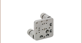
 Posts for Polaris<sup>®</sup> Mirror Mounts, Three Mounting Holes")
 Zoom
Zoom

Click to Enlarge
View Imperial Product List
View Metric Product List
The three tapped holes on these posts line up with the counterbores on Ø2" and Ø3" Polaris mirror mounts.
- Designed to Mount Ø2" and Ø3" Polaris Mounts
- Three Top-Located 8-32 (M4 x 0.7) Mounting Holes
- One Bottom-Located 1/4"-20 (M6 x 1.0) Mounting Hole
- Two Ø2 mm Alignment Pin Holes on Each End for Precision Mounting (Dowel Pins Not Included)
These posts feature three top-located 8-32 (M4 x 0.7) mounting holes and one bottom located 1/4"-20 (M6 x 1.0) mounting hole. They are designed to mount Ø2" and Ø3" Polaris mirror mounts, which have two and three #8 (M4) counterbores at each mounting face, respectively. This allows these large mirror mounts to be used on a post without sacrificing stability. The 8-32 (M4) mounting holes are arranged in a line with a center-to-center spacing of 0.37" (9.5 mm). Each end of the post has two Ø2 mm alignment pin holes located on either side of the central mounting hole.
A Ø6 mm alignment bore is located 20 mm from the bottom of the post and can be used in combination with our cage rods for the alignment of multiple mounts along a common optical axis or for fine angle tuning. Note that the alignment bore does not go completely through the PLS-T1 and PLS-T242/M posts. Instead, these posts contain two bores on opposite sides, within ±0.3°, that are 0.20" (5.1 mm) deep. Given their shorter length, a through bore would interfere with the mounting threads and prevent components from being securely attached to the post. Any post with a length of 1.49" (37.6 mm for metric posts) or less will have a similar alignment bore configuration.
Posts with three 8-32 (M4) mounting holes cannot currently be requested using the custom post configurator below. For custom post lengths and usage features, please contact Tech Support.
| Polaris® Mount and Post Interoperabilitya | ||||
|---|---|---|---|---|
| Item # | Post Length (L) | Resulting Optical Axis Height (Optic Center) | ||
| Ø2" Fixed Mount | Ø2" Kinematic Mounts | Ø3" Mounts | ||
| 1.00" | 2.25" | 2.40" | 3.00" | |
| 2.00" | 3.25" | 3.40" | 4.00" | |
| PLS-T238 | 2.38" | 3.63" | 3.78" | 4.38" |
| PLS-T3 | 3.00" | 4.25" | 4.40" | 5.00" |
| PLS-T4 | 4.00" | 5.25" | 5.40" | 6.00" |
| 56.0 mm | 59.8 mm | 75.0 mm | ||
| 81.0 mm | 84.8 mm | 100.0 mm | ||
| PLS-T605/M | 60.5 mm | 92.3 mm | 96.1 mm | 111.3 mm |
| PLS-T746/M | 74.6 mm | 106.4 mm | 110.2 mm | 125.4 mm |
| PLS-T996/M | 99.6 mm | 131.4 mm | 135.2 mm | 150.4 mm |