 Products Home
VantagePro® Resonant Scanner System
- ±13° Scan Angle and Beam Diameters Up to 5 mm
- 8 kHz Resonant Frequency for High-Speed Scans
- Easy to Integrate with OEM Systems
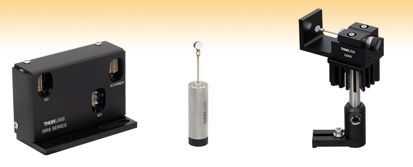
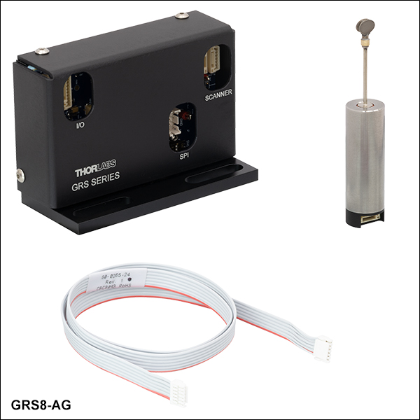
GRS8-AG
Resonant Scanner
Scanner with Mounted Protected Silver Mirror
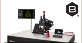
Application Idea
Post-Mounted GRS8-AG Resonant Scanner in a QSM5 Mount with GHS003 Heatsink
GRS8-AG
Resonant Scanner
Scanner Driver Board


Please Wait
| Table 1.1 Key Specifications | |
|---|---|
| Item # | GRS8-AG |
| Maximum Beam Diameter | 5 mm |
| Resonant Frequency (Nominal) | 7910 ± 15 Hz |
| Maximum Scan Angle (Opticala) | ±13° |
| Mirror Coating | Custom Protected Silver, 450 nm - 10.6 µm |
Applications
- Raster Imaging
- Laser Projection
- Video Microscopy
- Bio-Scientific Analysis
- Confocal Imaging
- Fluorescence Imaging
Features
- 8 kHz Resonant Scanner Frequency
- Accepts Beams Up to Ø5 mm
- Optical Scan Range of ±13°
- Power Supply, Command and Power Cables, and Scanner Mount Available Separately
Thorlabs' VantagePro® Resonant Scanner System is designed to rotate an optical scanning mirror at a high frequency to deflect a laser beam and continuously scan it over a user-controlled scan angle. This scanner drives a permanently installed mirror with a custom protected silver coating. The resonant frequency of the scanner is fixed at 8 kHz, enabling much higher-speed scans than a galvanometer system. Resonant scanners are often used as the fast axis of a 2-dimensional raster scanning engine, with common applications including video microscopy, bio-scientific analysis, and fluorescence imaging.
Resonant scanners are comprised of a multi-body spring-mass system, with scanning occurring at the fixed resonant frequency of the system. This resonant motion causes both the velocity and position of the scanner oscillate sinusoidally. The included driver board is designed to maintain the natural oscillation frequency and provide users the ability to control the scan angle. The driver monitors the scanner velocity and provides a sync pulse that can be used to synchronize other system components to the scanning motion.
The GRS8-AG resonant scanner utilizes a permanently attached mirror with a custom protected silver coating, which provides high reflectance in the visible and NIR. The mirror is elliptical, with axis diameters of 7.8 mm and 5.5 mm and a clear aperture of ≥90%, yielding a maximum beam diameter of 5 mm. The resonant scanner achieves an optical scan range of ±13°, representing the angular deflection of the reflected beam about the system's rotational axis. This corresponds to a ±6.5° mechanical scan range which is the angular rotation of the mirror itself. The fixed resonant frequency of the scanner is 8 kHz. Full specifications can be found in the Specs tab.
Each system includes a resonant scanner with a mounted mirror, a scanner driver board, and a ribbon cable for communication between the scanner and the driver board. Compatible power supplies, power and command cables, and an optional scanner mount are sold separately below.
| Resonant Scanner Specs | |
|---|---|
| Item # Prefix | GRS8 |
| Max Beam Diametera | 5 mm |
| Mirror Substrate | Beryllium |
| Resonant Frequency (Nominal) | 7910 ± 15 Hz |
| Mechanical and Electrical Specifiations | |
| Max Scan Angleb (Opticalc) | ±13° |
| General Specifiations | |
| Operating Temperature (Non-Condensing) | 0 °C to 40 °C |
| Storage Temperature | -10 °C to 50 °C |
| Stator Body Size | Ø0.63" x 1.97" (Ø15.9 mm x 50.0 mm) |
| Scanner Length | 3.36" (85.4 mm) |
| Scanner Mass | 45 g |
| Driver Board Dimensions (L x W x H) | 3.49" x 1.50" x 2.36" (88.7 mm x 38.1 mm x 60.2 mm) |
| Driver Board Mass | 226 g |
| Mirror Coating Specs | |
|---|---|
| Item # Suffix | -AG |
| Coating Type | Custom Protected Silver |
| Absolute Reflectance | ≥92% (450 - 500 nm) ≥94.5% (500 - 2000 nm) ≥98% (2 - 10.6 µm) |
| Surface Quality (Scratch-Dig) | 40-20 |
Figure 3.1 respresents how the resonant frequency of the GRS8-AG resonant scanner will vary with temperature. Figure 3.2 displays how the typical scan angle for the resonant scanner changes with voltage.

Click to Enlarge
Click Here for Data
Figure 3.2 Typical data for how the half scan angle of the GRS8-AG resonant scanner changes with voltage. This half angle gives the deviation from the center position of the mirror, so the total scanning angle is twice what is shown. Establishing a series of at least 5 reference points to generate a calibration curve is recommended.
Click to Enlarge
Click Here for Data
Figure 3.1 The typical resonant frequency shift of the GRS8-AG resonant scanner with respect to temperature.
Figures 3.3 and 3.4 represent the response of the resonant scanner driver board to an abrupt step change in scan angle from ±12° down to ±7°. This step change occurs when time is at 10 seconds.
Click to Enlarge
Click Here for Data
Figure 3.3 The typical rising edge frequency of the GRS8-AG resonant scanner for an abrupt step change in scan angle, showing the time it takes the resonant frequency to stabilize. At a time of 10 s, the scan angle is changed from ±12° down to ±7°.
Click to Enlarge
Click Here for Data
Figure 3.4 The typical rising delay of the GRS8-AG resonant scanner is shown. This shows the change in the delay between the sync trigger pulse and the motion of the scanner mirror for an abrupt step change in scan angle. At a time of 10 s, the scan angle is changed from ±12° down to ±7°.
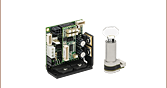
Components Included with Resonant Scanner System
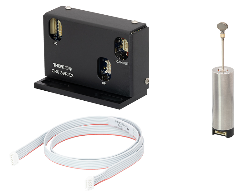
Click to Enlarge
Figure 4.1 Components shipped with GRS8 series Resonant Scanners
GRS8 Series VantagePro® Resonant Scanner System
- Resonant Scanner Body with Mounted Mirror
- Scanner Driver Board
- 24" Scanner to Driver Ribbon Cable
Required Items Not Included with Resonant Scanner System
| Scanning Methodology Differences | |
|---|---|
| Galvanometer-Based Scanning |
Flexible Scan Positioning Slower Scan Speeds Up to 1.2 kHz |
| Resonant Scanning |
Faster Fixed Scan Speed of 8 kHz Mechanically Fixed Center of Scan Sinusoidal Velocity Profile |
Galvo Versus Resonant Scanning
Galvo and resonant scanning systems provide complementary advantages due to their different scanning mechanisms. As a result, it is important to choose the scanning methodology best suited to the intended application. For instance, galvo scanning is optimal for user-defined scanning paths and shapes, while resonant scanning is optimal for high-speed scanning.
Galvanometer-based scanning systems use a galvanometric mirror steered by a servo-controlled motor and a positioning actuator. The angle of the mirror can be controlled via an external signal for accurate positioning and scanning, providing the flexibility for user-defined scan lines and areas. Due to the inertia of the system, the velocity of a galvo scanner has a lower upper limit.
While resonant scanning also utilizes a galvanometric mirror, the mechanism that drives the mirror differs significantly. In a manner similar to that of a tuning fork, the mirror assembly is driven at its resonant frequency in order to reach over 6X faster scan speeds than that of galvo scanning. The only user-variable parameter of the resonant scan mirror motion profile is the scan angle. The scanner mirror motion is always sinusoidal, which requires different signal processing and optimization techniques compared to the arbitrary location pointing capability of a galvanometer. The driver contains a phase locked loop (PLL) to provide a sync signal precisely timed with the motion of the scanner.
| Posted Comments: | |
| No Comments Posted |

 Zoom
Zoom- 8 kHz Resonant Scanner Frequency for High-Speed Scans
- Max Scan Range of ±13° Optical
- Custom Protected Silver Mirror for High Reflectance in Visible and NIR (450 nm to 10.6 µm)
- Includes Scanner, Driver Board, and Ribbon Cable for Communication
Thorlabs' GRS8-AG VantagePro® Resonant Scanner System is ideal for high-speed imaging. The resonant scanner is comprised of a mirror with a custom protected silver coating, which provides high reflectance in the visible and NIR, mounted to a scanner body. This mirror allows for a maximum beam diameter of 5 mm. The scanner offers a large scan field, with an optical scan range of ±13° (±6.5° mechanical scan range), and operates at a resonant frequency of 8 kHz.
Each GRS8-AG resonant scanner system includes the resonant scanner with mounted mirror, a scanner driver board, and a 24" ribbon cable for communication between the scanner body and the driver board. Control of the resonant scanner can be achieved using either the 9-pin I/O connector or the 8-pin SPI connector, both located on the driver board. More information on controlling the resonant scanner system can be found in the manual, by clicking on the Docs (![]() ) icon below.
) icon below.
A compatible GPS011 series Linear Power Supply and CBLA2P Command and Power Cable, or GPWR15 Power Supply and CBLA2F Command and Power Cable can be purchased separately below. For safe and easy integration into optical setups, a compatible QSM5(/M) mount for the resonant scanner body is also sold separately below.

 Zoom
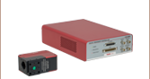
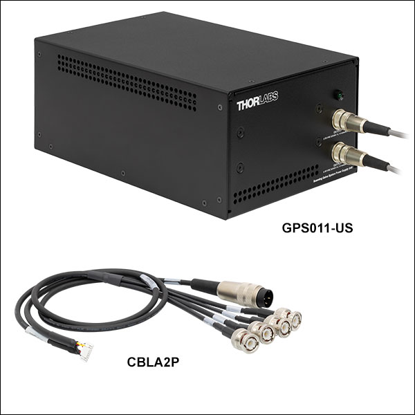
Zoom- GPS011 Series: ±15 V Power Supply for Single- and Dual-Axis Systems; One Supply Can Power up to Two Galvos
- QG4, QG5, QS7, QS10, QS15, and QS20 Series VantagePro® Galvanometer Scanners
- GRS8-AG Resonant Scanner
- BLINK Focusers
- 2-Axis XG Series Scan Heads
- GPS011 Series Specs:
- Enclosed Unit Allows Cables to Directly Connect to the System
- Switchable Input: 100 VAC / 50 or 60 Hz, 115 VAC / 60 Hz, 230 VAC / 50 Hz
- Output: ±15 VDC @ 3 A
- Operating Temperature: 5 to 40 °C
- Dimensions: 7.05" x 10.79" x 4.8" (179 mm x 274 mm (Max) x 122 mm)
- CBLA2P: Interface and Power Cable for GRS8 Series Resonant Scanners
The GPS011 Series Power Supplies are low noise, linear supplies designed to minimize electrical interference for maximum system resolution for 1D and 2D galvanometer systems. The compatible systems include the QG4, QG5, QS7, QS10, QS15, and QS20 Series Galvanometers Scanners, the GRS8-AG Resonant Scanner, the BLINK Focusers, and the 2-Axis XG Series Scan Heads. These power supplies deliver ±15 VDC at 3 A and are configured to accept a mains voltage of 115 VAC (Item # GPS011-US), 230 VAC (Item # GPS011-EC), or 100 VAC (Item # GPS011-JP). The GPS011 units are enclosed, allowing for direct connection with the compatible power cable without soldering.
Please note that the GPS011 series power supplies are insufficient for driving the QS30/45 Scanning Galvanometer Systems. Additionally, for the compatible galvos, Thorlabs recommends keeping the RMS current at 1 A or below.
The CBLA2P Power and Interface Cable can be used to connect the GPS011 series galvo system linear power supplies to the GRS8-AG resonant scanner. The cable consists of a nine pin connector on one end for compatibility with the GRS8 series resonant scanner and five connectors on the other end for compatibility with the GPS011 series power supply as well as a user-supplied controller. The three-pin circular connector provides compatibility with the GPS011 series, while the four BNC connectors provide compatibility with a user-supplied controller.

 Zoom
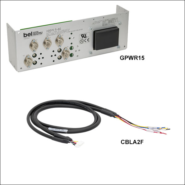
Zoom- GPWR15 Power Supply: ±15 V Power Supply for Single- and Dual-Axis Systems; One Supply Can Power up to Two Galvos
- QG, QS, SS, and SP Series VantagePro® Galvanometer Scanners
- GRS8-AG Resonant Scanner
- BLINK Focusers
- XG Series Scan Heads
- GPWR15 Power Supply Specs
- Open Frame Requires Cables to be Soldered In
- Input: 100-120 or 220-240 VAC
- Output: ±15 V @ 5 A (150 W Max Power)
- Operating Temperature: 0 to 50 °C
- Dimensions: 14.0" x 4.9" x 3.5" (356 mm x 124 mm x 90 mm)
- CBLA2F: Command and Power Cable for GRS8 Series Resonant Scanners
The GPWR15 Power Supply is a low noise, linear supply designed to minimize electrical interference for maximum system resolution. The compatible systems include the QG, QS, SS, and SP series Galvanometers Scanners, the GRS8 series Resonant Scanners, the BLINK Focusers, and the XG Series Scan Heads. This power supply delivers ±15 VDC at 5 A and is configured to accept a mains voltage of 100 - 120 or 220 - 240 VAC. It has an open frame, allowing the user to solder the compatible power cable into the system.
The CBLA2F Command and Power Cable can be used to connect the GPWR15 power supply to the GRS8-AG resonant scanner. The power cable has a four pin connector on one end for compatibility with the QS7/10 galvos and BLINK focusers and three bare wires for soldering to the GPWR15 power supply on the other end. The command cable has a two pin connector on one end for compatibility with the QS7/10 galvos and BLINK focusers and three bare wires for soldering to a user-supplied controller on the other end.

 Zoom
Zoom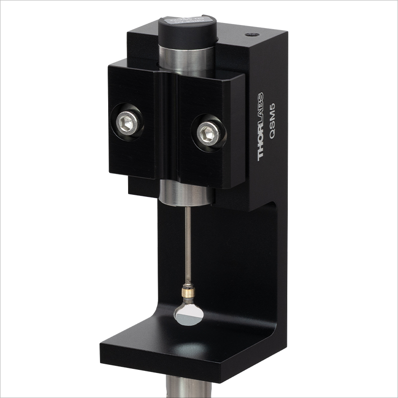
Click to Enlarge
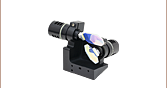
Figure G4.3 A GRS8-AG scanner is post-mounted in the QSM5 mount in a vertical orientation.
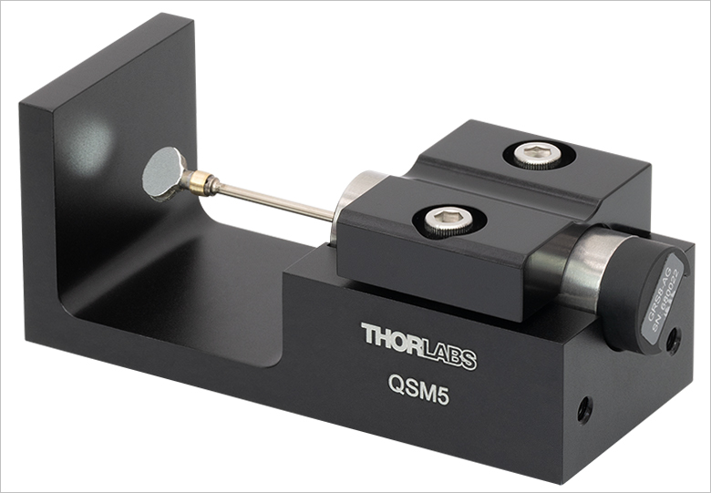
Click to Enlarge
Figure G4.2 A GRS8-AG resonant scanner is mounted in the QSM5 mount.
| Table G4.1 Specifications | ||
|---|---|---|
| QSMx Mount | Drawingsa | Compatible Scanner |
| QSM5(/M) |  |
GRS8-AG |
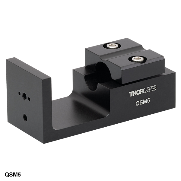
- Mounts for Resonant Scanner (Sold Separately Above)
- Two-Piece Clamp Mechanism Avoids Contact With Mirror Surfaces
- Vertical or Horizontal Mounting on Posts or Translation Stages
- Dowel Hole/Slot Design for Repeatable Precision Mounting on MT Translation Stages
- Compatible with GHS003(/M) Heatsinks
Thorlabs' QSM5(/M) mount provides a convenient solution for mounting the resonant scanner sold above. The holes available for mounting on our posts or translation stages in either vertical or horizontal orientations are shown in the drawings in Table G4.1. The scanner is secured using a two-piece clamp, allowing it to be installed without passing the sensitive mirror through the mount. For applications that require additional heat dissipation, all mounts are compatible with the GHS003(/M) heatsinks.