 Products Home / Fiber Fusion Splicers and Processing Equipment / Portable Connector End Face Geometry Interferometer
Portable Connector End Face Geometry Interferometer

- Automated, Compact Interferometer Controlled through USB Port
- Precise, Fast Measurements of Radius of Curvature, Apex Offset, and Fiber Height
- User-Friendly Software Compatible with Windows® 7, 8, or 10
CC6000
Pass/Fail Limit Regions Streamline Production Line Integration
3D View Provides Intuitive Understanding of Geometry


Please Wait
Click to Enlarge
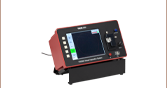
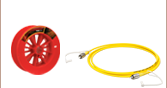
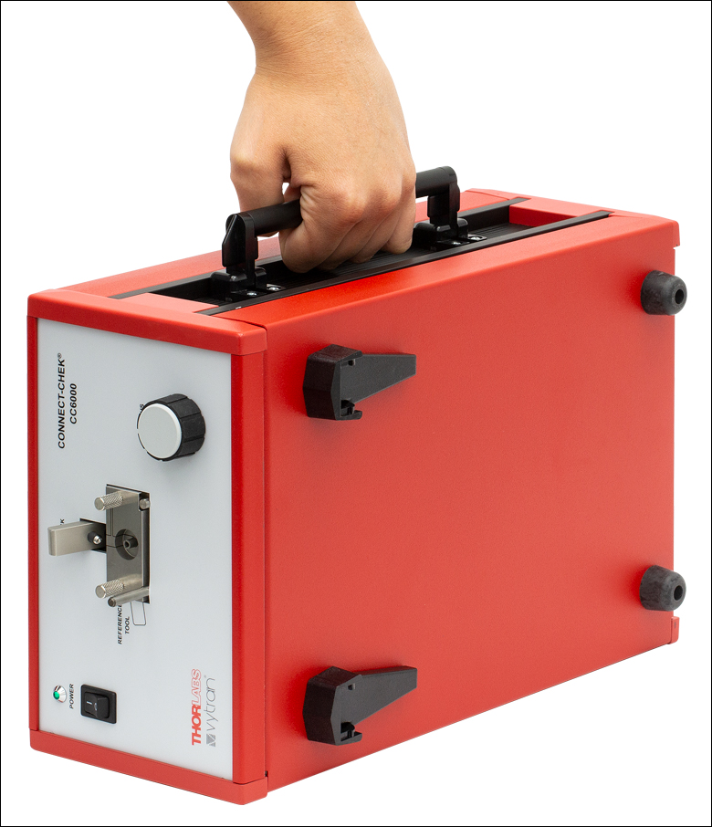
This portable interferometer, with integrated carrying handle, is designed for use in production as well as the field.
Click to Enlarge
The included software's Live View allows a user to adjust focus in real time for maximum contrast, ensuring high accuracy and quick measurement time.
| Item # | CC6000 | ||
|---|---|---|---|
| Measurement Specifications | Range | Repeatabilitya | Reproducibilityb |
| Radius of Curvature | 3 - 50 mm | 1% | 2% |
| Apex Offset | 0 µm - 100 µm | 2 µm | 4 µm |
| Spherical Fiber Height | ±160 nm | 5 nm | 10 nm |
| Interferometer Specifications | |||
| Dimensions (L x W x H) | 13.9" x 8.8" x 5.9" | ||
| Light Source | LED (660 nm) | ||
| Camera Sensor | CCD, 5.79 mm x 4.89 mm Sensing Area | ||
| Measurement Lateral Resolution | 1 µm | ||
| Magnification | 10X Objective | ||
| Field of View (H x V) | 358 µm x 336 µm | ||
| Computer Minimum Requirements | |||
| Speed | Pentium IV 1.5 GHz | ||
| USB | 3.0 | ||
| Operating System | Microsoft® Windows® 7, 8, or 10 | ||
| RAM | 2 GB | ||
Features
- Automated, Non-Contact Analysis of Single-Fiber Connector End Faces
- Quickly Measure Radius of Curvature, Apex Offset of Polish, and Fiber Undercut or Protrusion
- Minimal Need for Refocusing Coupled with No Regularly Moving Components
- Software can be Installed on PC (Not Included) with Windows® 7 or Higher
- Interchangeable Mounts for Ø1.25 mm to Ø2.50 mm Ferrule, PC or APC, Single-Fiber Connectors
Thorlabs’ Vytran® Connect-Chek® Interferometer automatically and precisely measures radius of curvature, apex offset of polish, and fiber undercut or protrusion on any PC or APC, single-fiber connector. The CC6000 interferometer uses a non-contact tilted-phase-analysis technique for fast, reliable measurements of connector end faces. This compact interferometer has a carrying handle and must be attached to a desktop or laptop computer (not included) with a standard USB 3.0 port for operation. The included CC6000 software, which is used to control the interferometer, can be installed on a computer with the minimum requirements in the table below. Designed for use in both the factory and the field, this interferometer provides crucial quality information needed to assure long-term performance of fiber optic connectors. One CC250P Mount for Ø2.50 mm PC Connectors and one RT250P Reference Tool for calibrating the CC250P mount are included with the CC6000 interferometer; mounts and reference tools that enable measurement of other PC or APC, single-fiber connectors are available separately below. When used with an appropriate mount for APC connectors, the CC6000 interferometer is also capable of measuring the APC angle and key error.
Software Interface
The user-friendly software allows anyone with minimal experience to accurately measure the end face geometry of a fiber optic connector. After performing a non-contact interferometric measurement of the fiber optic connector end face, the CC6000 interferometer will automatically generate a 3D image showing the measured radius of curvature, apex offset, and fiber height. This immediate visual feedback on the end face geometry of the connector aids users in understanding quality control and quality assurance issues, allowing them to get the most from their high performance fiber optic connectors. The software's user interface is simple and easy to learn, with every option visible under intuitive Menu Tabs. Measure, Setup, Calibration, or History windows can be brought up with a few clicks. Preset scan criteria can be loaded to allow pass/fail measurements of PC connectors using IEC, Telcordia, or your own custom standards. Data can be saved to an Excel file in any directory locally or on a network and is also saved on a SQL database. See the Software tab for more details.
Tilted Phase Analysis
The CC6000 Connect-Chek® interferometer uses a unique tilted phase analysis, in which the connector is held at a slight tilted angle so that interferometry produces circular fringes across the connector end face. This interferometry provides all the information needed to measure the connector without the need for costly phase-shifting devices. After a simple calibration to measure the tilt, the spherical radius of curvature, spherical fiber height, and apex offset of the connector are calculated using advanced algorithms (see the Measurement tab for more details). An added advantage of tilted phase analysis is that any small angle is suitable, so no mechanical adjustments are required. This lack of mechanical adjustment enables the measurements to be as fast as 1 second and the device to be easily maintained.
Click to Enlarge
Diagram showing apex offset of polish.
Click for Details
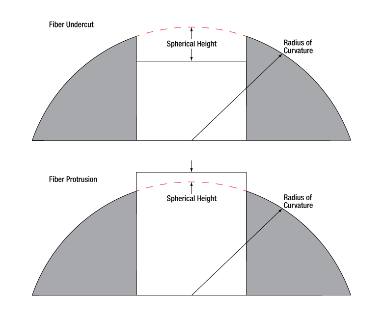
Diagram showing radius of curvature and spherical fiber height.
Single-Fiber Measurement
Interferometry creates a circular fringe pattern on the connector, which may be visualized as a topographical map of the surface. Each fringe is a half-wavelength distance above or below adjacent fringes, showing the height difference across the surface. Definitions and measurement methods for each of the measured values are described below. For more information on reading interferograms, see the Interferograms tab.
Radius of Curvature
Radius of curvature is the average curvature radius (in mm) of the connector end face. It is defined as the radius of the best-fit curvature over the specified fitting area, calculated by using a least-squares method. Although typically a sphere is the best-fit model, an ellipsoid may be used for high or low radius of curvature.
The spherical radius of curvature is directly correlated to the diameter and spacing of the circular fringe patterns generated by the interferometer.
Spherical Fiber Height
Fiber height is the amount of undercut or protrusion (in nm) of the fiber in the connector. It is defined as the difference between the height at the center of the fiber and the spherically projected height of the ferrule at the same location.
When the connector is tilted slightly off axis, any changes in the circular fringe pattern at the boundary between fiber and ferrule is an indication of fiber protrusion or undercut. These changes are proportional to a change in fiber height, allowing the unique algorithms of the CC6000 software to take advantage of this information to measure the spherical fiber height.
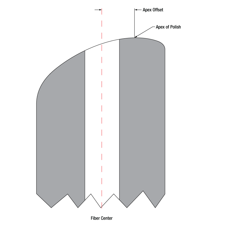
Apex Offset
The apex offset is defined as the difference between the apex of the ferrule's spherical end face and the center of the fiber. As seen in the image to the right, the apex offset can be quantified as a linear distance offset (in µm).
When the connector is perpendicular to the optical path, as in a traditional interferometer, the apex offset is the distance from the center of the fiber to the highest point of the polish. The CC6000 interferometer is able to calculate the apex offset of the polish even in the preset tilted position of the connector. Rotating the connector will not change the offset measurements because the center of the fiber is the center of rotation for the ferrule. If the connector is held in a tilted position relative to the optical path, the apex offset is the distance from the center of rotation to the highest point of the polish.
Software
Version 8.2 (Build 1.23.12.4)
Click the button below to visit the CC6000 software page.
The CC6000 Portable Interferometer includes a measurement software program that must be installed and run on computers with Windows® 7, 8, or 10 and a USB 3.0 port. The software is navigated with an intuitive structure of menus and tabs, keeping essential tools in the forefront. Measurements can be taken in as little as 1 second, displaying "Pass" or "Fail" above the measured values for efficient production line use. Alternatively, for more detailed examination, a user can switch to the 3D view and show results in Scale Mode to see indicators showing the pass/fail limits. Administrator-level users have control of almost all software functions, including calibration capabilities and program configurations. Operator-level users can load pre-set configurations by clicking on the Load Settings button. By default, the data is saved to an Excel file in any directory locally or on a network, and also saved to a SQL database. Measurements for each connector can then be selected in the software for printing in a custom report. Below are a several sample screenshots showing some of the key features of the CC6000 software.
Software Features
Click to Enlarge
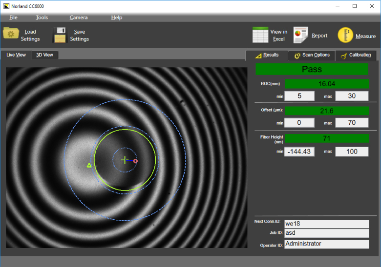
Live View
The Live View tab shows the interferogram generated by the CC6000 light source, with key measurement regions, fiber center, and apex of polish overlayed. This tab is used for focusing the interferometer prior to measurements.
Click to Enlarge
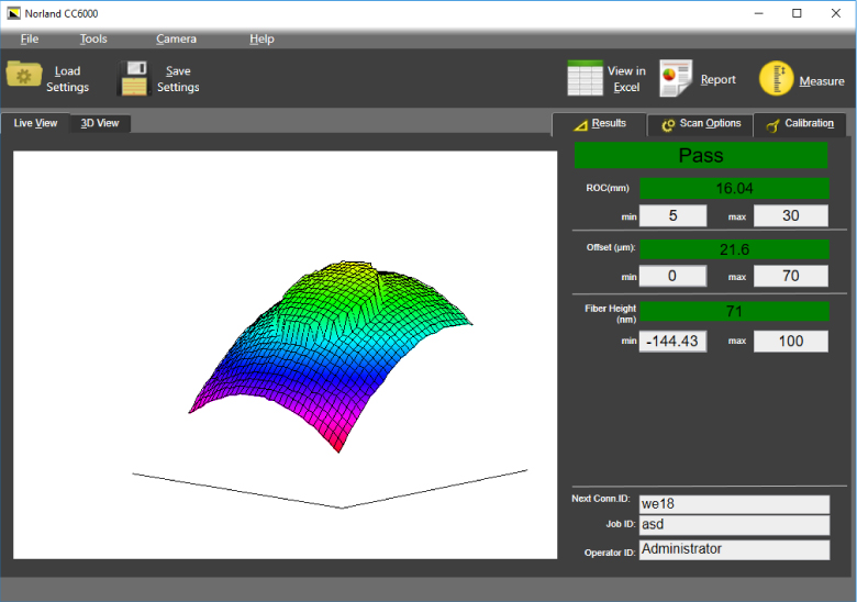
3D View
The 3D View tab displays a software-computed model of the connector end face, generated from the measured connector parameters. This 3D view can be rotated and zoomed, enabling an interactive, intuitive perception of the connector end face.
Click to Enlarge
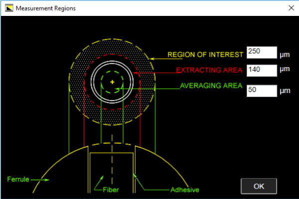
Measurement Regions Control
Users have a high level of customization regarding the measurement process, including configuration of the regions used for measurement, as shown above.
Click to Enlarge
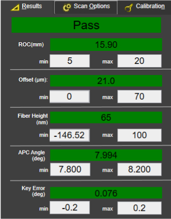
Results Tab, Value Mode (APC Connector)
This value-based display of the results allows for a quick reading; criteria that pass will be green, while those that fail will be shown in red.
Click to Enlarge
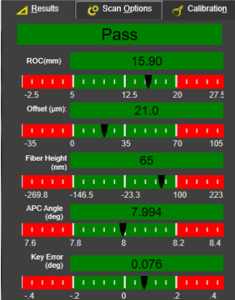
Results Tab, Scale Mode (APC Connector)
This scale-based display of the results enables quick visual assessment of the results with respect to their limits; users may see the trend of successive measurements and adjust their process to prevent failed connectors.
Click to Enlarge
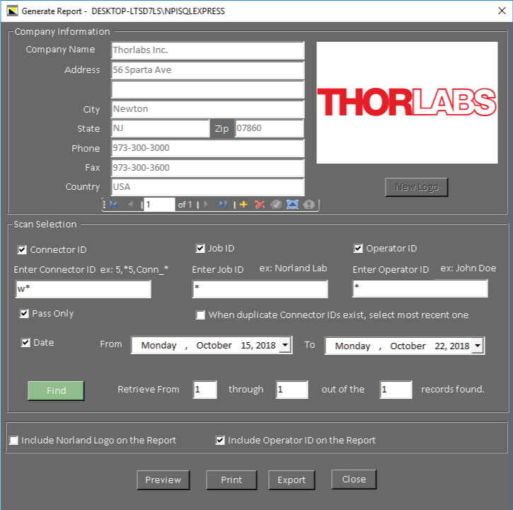
Generate Report Window
Printed reports can be customized with company information, logo, and operator ID. The range of scans to be printed can be selected using a variety of fields such as connector ID, operator ID, and date.

Click to Enlarge
Sample Report
Each printed report contains a 3D view of the connector, the key measurement parameters, and various additional information as determined by the user.
Front and Back Panels

Click to Enlarge
Front Panel
Click to Enlarge
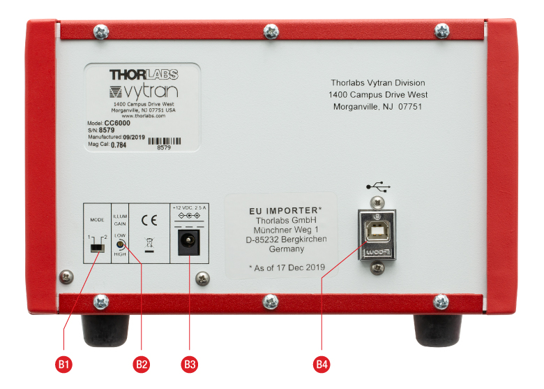
Back Panel
| Front Panel | |
|---|---|
| Callout | Description |
| F1 | Power On/Off Status Lamp |
| F2 | Power Switch |
| F3 | Connector Fixture |
| F4 | Connector FIxture Locking Lever |
| F5 | Focus Adjustment |
| Back Panel | |
|---|---|
| Callout | Description |
| B1 | Ferrules Material Switch (1 - Ceramic, 2 - Metal), Provides Coarse Brightness Adjustment |
| B2 | Illumination Gain Adjuster, Provides Fine Brightness Adjustment |
| B3 | +12 VDC Power Input |
| B4 | USB 2.0 Type B Port |
Reading Fiber Optic Interferograms
Inspection interferometers split light from a source between a reference flat and a surface under test. By recombining the beams of the reference arm and sample arm, an interference pattern is created allowing imperfections in a fiber tip to be inspected without making physical contact.
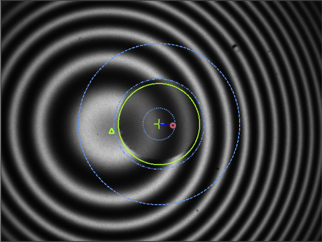
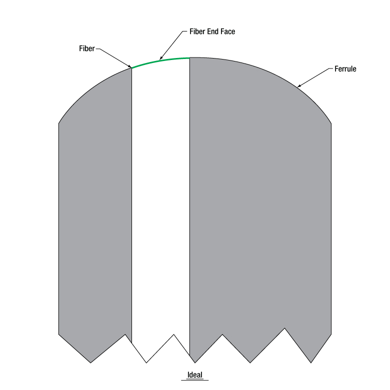
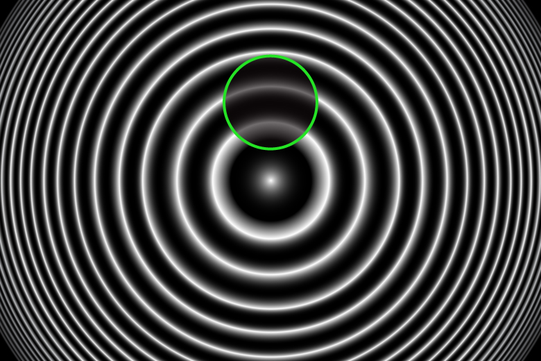
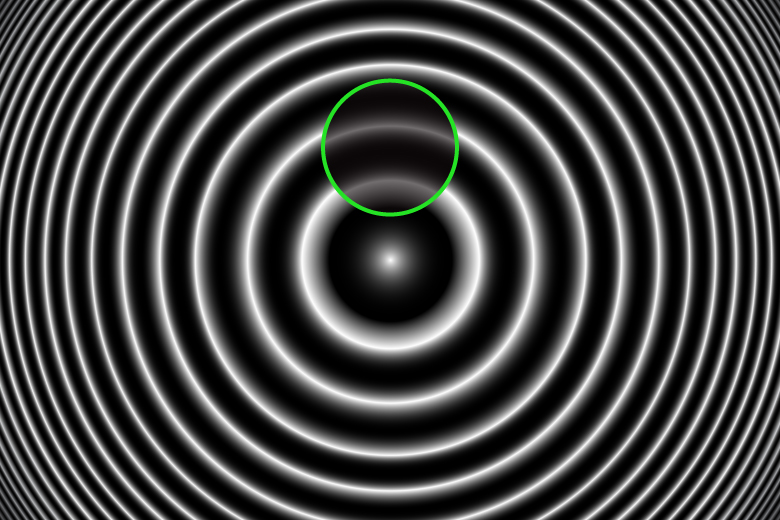
When produced perfectly, fibers are polished to match the height, curvature, and angle of their ferrule tip. With no imperfections, the fiber end face will seamlessly match the rest of the ferrule tip. This interferogram will be a bullseye of alternating constructive and destructive interference, or fringes (Figure 1). The location of the fiber end is marked in green on the fiber schematics and circled in green on the interferograms. Note that the fiber is not perfectly centered in the ferrule. There will be a small offset between the fiber center and the apex of polish; often, an off-center fiber can make disturbances in the interferogram easier to see, as the fiber interacts with more fringes.
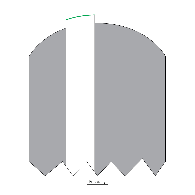
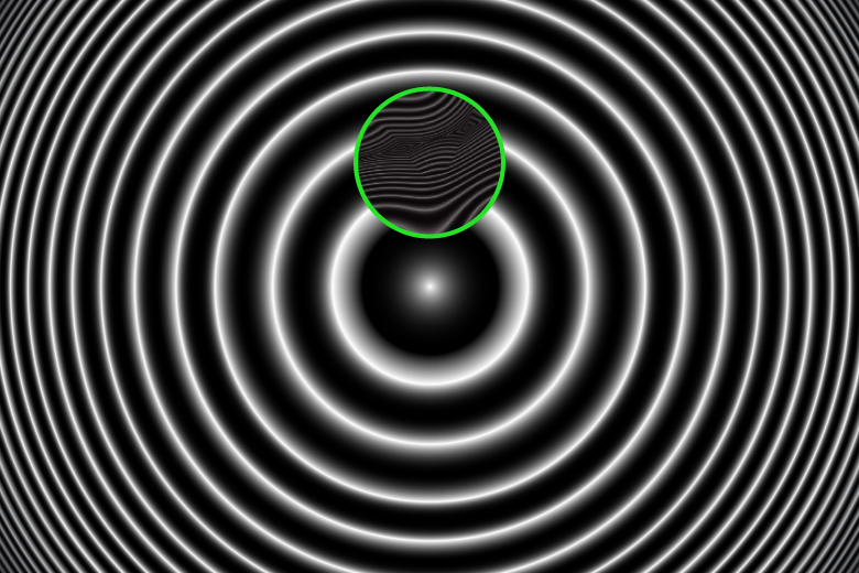
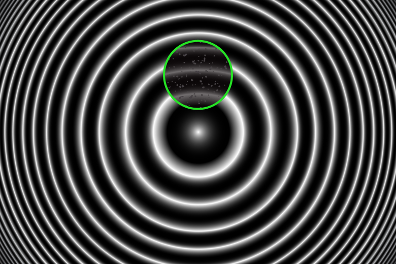
Deviations from an ideal polish will result in visible distortions within the green-circled region of the interferogram. If a fiber end protrudes past the surface of the ferrule, the interferogram will show a distortion that advances the fringe pattern away from the ferrule's apex of curvature (Figure 2). If a fiber end is undercut, the interferogram will show a distortion with retreats from the apex of curvature (Figure 3). An undercut fiber could collect dust, which will either absorb or scatter light, causing dots to appear in the interferogram (Figure 4). If a fiber end has shattered in the polishing process, the interferogram will be highly irregular (Figure 5).
 Click to Enlarge
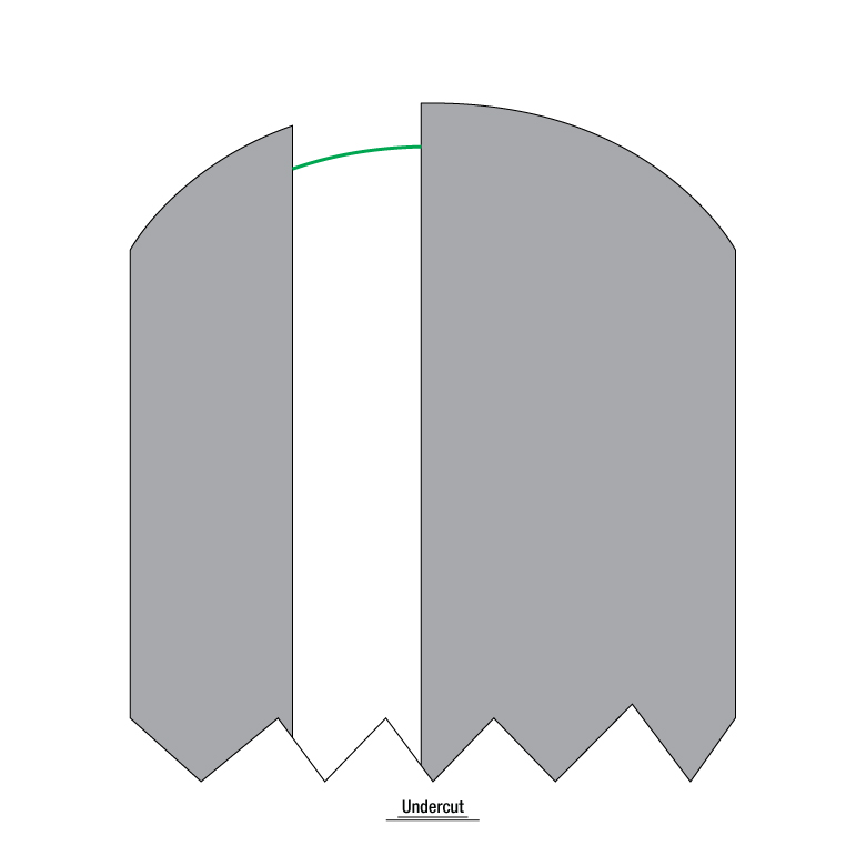
 Click to Enlarge
 Click to Enlarge
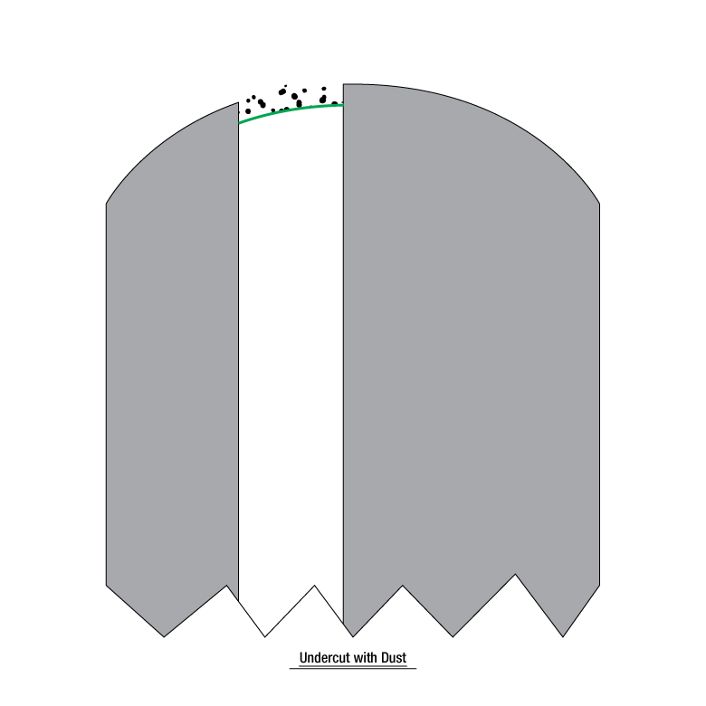
 Click to Enlarge
Calibration
The CC6000 is a non-contact interferometer for single-fiber fiber optic connector end face geometry (EFG) measurements. EFG characterization is mandated by industry standards such as Telcordia GR-326 and IEC 61755-3-1/2 for use as a complement to optical testing towards producing a high quality end product.
On a production line, EFG testing will typically be used early in the cable manufacturing process, with optical testing to follow. In this way, problems with polishing can be caught and corrected, resulting in less rejection of material and higher throughput. EFG testing can also be placed after optical testing and, as such, be useful for final confirmation and documentation of product cleanliness as well as performance with respect to industry pass/fail specifications.
Proper calibration of your EFG instrument is critical to a good production process. Small differences in attaching a mount prior to use, minute particles of dust captured between the mount and front panel surface, and general wear of the mount and its locking mechanism all play a role in the repeatability and accuracy of measurement results. Due to these variables, it is necessary to run the Offset Calibration procedure whenever a mount has been reattached after cleaning or changed for a different mount.
Methods
There are two Offset Calibration methods available with the CC6000 software: using Reference Tools, or using Leveling Connector. Both methods result in correction factors that get applied in the software to the measurement results, compensating for any difference between the CC6000’s optical axis and the measured connector axis. The Leveling Connector method can provide better calibration accuracy as compared to the Reference Tools method, but at the cost of taking longer to perform, and only being applicable to PC mount calibration (since an angled mount does not allow for the required calibration tool rotation).
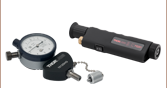
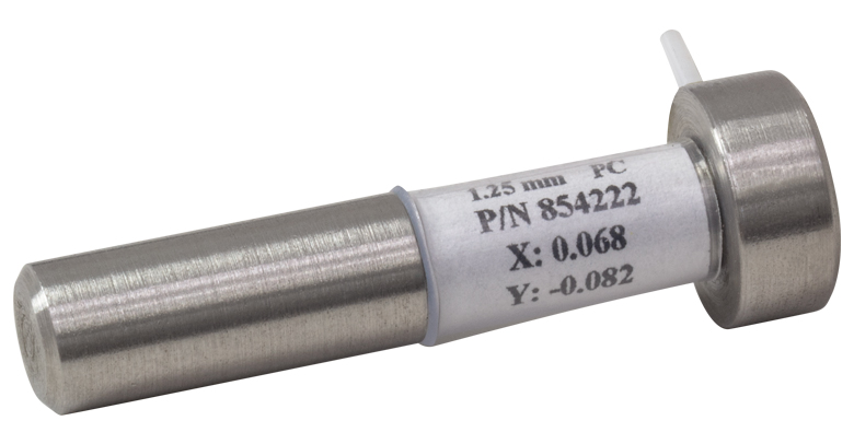
- For the Reference Tools calibration method, a connector (as shown to the right and sold below) with endface of known geometry parameters is inserted into a CC6000 mount of same ferrule diameter, positioned with its arm resting on the post to the left of the mount, and measured. The known X and Y angular offset angles are compared to the actual measurement
results from the calibration procedure and correction factors are calculated so the known values equal the measurement results. This method is applicable to both PC
and APC mount calibration.

Click to Enlarge
Leveling Tool
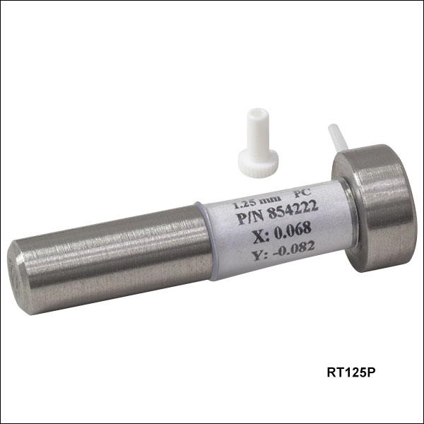
- For the Leveling Connector calibration method, a leveling tool (as shown to the right and sold here) is inserted into a CC6000 mount of same ferrule diameter and measured at eight different rotational positions (ideally approximately 45 degree difference between each position). The software calculates the correction factors by noting the difference between center of rotation and center of the fiber. This method, however, is only applicable to PC mount calibration.
Furthermore, Magnification Calibration of the CC6000 is performed at the time of construction, with its calibration factor stored internally to the instrument. This calibration should not need to be run by the end user unless there is reason to suspect damage or physical change to the CC6000. Please contact Technical Support for instructions to perform this calibration.
Considerations
In addition to calibration protocols as described above, there are a few procedures that, if unsuccessful, not performed, or not followed correctly, can lead to erroneous measurement results:

Click to Enlarge
Successful Reference Tool Calibration Procedure
- When creating new Reference Tool records in the CC6000 software, be sure to enter values with signs for the X and Y factors exactly
as marked on the tool. - Before running a measurement, make sure the correct Reference Tool has been selected.
- After completion of an Offset Calibration, check the success of the calibration by confirming that the green circle aligns with the outer
edge of the tool’s fiber hole. If it does not, use focus adjustments to make sure that the interference fringes are at maximum contrast, especially near the fiber area. Then rerun the calibration.
Though the CC6000 is a robust instrument with few moving parts, there are a number of conditions over long term use that can lead to larger variations in results upon repeated measurements, or loss of accuracy in measurements:
- Light source (Red LED) intensity reduction
- Mount wear due to repeated insertion of ferrules, especially when polish residue remains on outside of ferrule
- Excess wear of locking-lever threaded plunger.
| Posted Comments: | |
user
(posted 2024-06-29 18:57:43.367) I was wondering if it would still be possible to get the manual for an older Norland product, the Cleave-Chek. Unfortunately I have a unit that is missing the manual. jdelia
(posted 2024-07-03 08:52:44.0) Thank you for contacting Thorlabs. I have reached out to you directly via email to share this manual. Matthew Hessenthaler
(posted 2023-10-27 14:38:18.437) I just received the CC250SAF mount and I am having trouble with it. I am assuming that the mount is designed at an angle such that when measuring an SC/APC Connector it is flat with respect to the laser? What is the correct orientation because I am unable to plug in my SC/APC connector in this orientation where it is flat. When it is turned 90 degrees either way I am able to plug it in, yet I cannot view any fringes since the ferrule is not flat wrt the laser. Any feedback would be appreciated. cdolbashian
(posted 2023-11-15 04:38:13.0) Thank you for reaching out to us with this inquiry. I have contacted you directly with some troubleshooting steps. Frank Bertotti
(posted 2023-07-19 08:19:04.577) Does the cc6000 measure Panda Fiber? Multi-fiber?
Thanks jdelia
(posted 2023-07-24 09:43:10.0) Thank you for contacting Thorlabs. This should generally be fine, as long as a compatible connector type be used (according to the Overview section of the product family page). I have reached out to you directly to clarify your question and discuss your application further. Adrian Stinger
(posted 2021-03-05 09:44:50.02) I have a CC6000 running on a XP machine, and would like to upgrade that machine to windows 10 if possible. How can I check the compatibility of my current interferometer with Windows 10? I have tried installing our current version of software on a Win10 machine and cannot get an image from the interferometer when you launch the program. Thank you asundararaj
(posted 2021-03-08 01:26:45.0) Thank you for contacting Thorlabs. Our team will reached out to you directly regarding this. Bob Kinney
(posted 2020-11-24 09:46:57.907) I have 2 Norland CC6000 units and they only work with Windows XP. Can I send them in for upgraded software or other option? Thanks YLohia
(posted 2020-11-25 01:43:42.0) Hello, thank you for contacting Thorlabs. Software options depend on the specific hardware version you have. We have reached out to you directly to discuss this further. Janusz Sek
(posted 2019-10-22 08:10:29.403) Please send me your quote for CC6000 interferometer. YLohia
(posted 2019-10-22 09:17:08.0) Thank you for your interest in the CC6000 Portable Connector End Face Geometry Interferometer. Quotes for stock items can be requested from your cart or emailing us at sales@thorlabs.com. We will reach out to you directly. user
(posted 2019-04-22 12:50:53.553) Please refer to description of CC6000 namely., '' When used with an appropriate mount for APC connectors, the CC6000 interferometer is also capable of measuring the APC angle and key error.''
May we know the range, repeatability & reproducibility for APC angle and key error measurements? YLohia
(posted 2019-05-01 08:28:42.0) Hello, thank you for your feedback. Our engineering team is now working on establishing a spec for what you asked and will update the website and product literature once it has been compiled. We will update you via email as soon as we have more information to share. |

 Zoom
ZoomComponents Included
- CC6000 Connector End Face Geometry Interferometer
- External Power Supply
- Region-Specific Power Cord
- End Face Geometry Measurement Software*
- Operation Manual
- CC250P Mount for Ø2.5 mm PC Connectors
- RT250P Reference Tool for Calibration of Mount
- Fiber Connector Cleaner
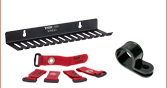
Optional Purchases
- Locking V-Groove Mounts
- Reference Tools
*Computer with USB 3.0 port required for operation (not included). See minimum requirements in the Overview tab.
- Robust, Compact Construction
- Integrated Carrying Handle for Ease of Transport
- Recalibration Only Needed after Attaching Mount
- Additional Mounts and Reference Tools Sold Below
The CC6000 Portable Interferometer is a compact unit for non-contact analysis of connector end face geometry. It is shipped with all the items described to the right, allowing for measurements of Ø2.5 mm PC connectors once connected to a computer (not included) with the minimum requirements described in the Overview tab. To measure a wide variety of other connector types, additional locking V-groove mounts must be purchased, for which a corresponding reference tool is needed for calibration (see table below). The CC6000 interferometer will measure the radius of curvature, apex offset, and fiber height of all connectors. For APC connectors, the interferometer can also measure the APC angle and the key error, when the appropriate mount and reference tool (sold separately below) are used.
The CC6000 interferometer is designed for accurate measurements in production or field environments. Precision offset measurements are facilitated by our locking v-groove mount (sold below) which holds the connector in an exact, repeatable position during calibration and measurement. The system has been optimized to provide maximum stability, eliminating the need for recalibration except when reattaching or exchanging mounts. Refocusing is also reduced with no regularly moving components and limited exposure of optical components to environmental contamination.

 Zoom
Zoom| Mount and Reference Tool Selection Guide | ||
|---|---|---|
| Locking V-Groove Mount Item # |
Compatible Connector Type | Required Reference Tool Item # |
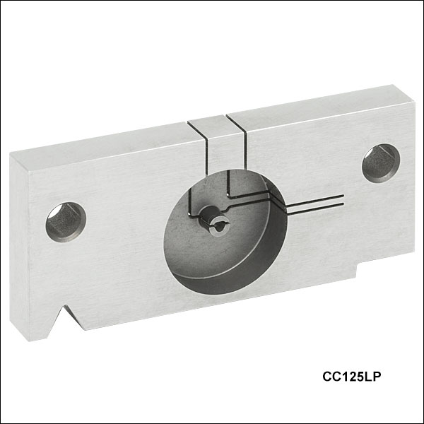
| CC125LP | Ø1.25 mm Ferrule LC/PC Connectors | RT125P |
| CCDUPLP | Ø1.25 mm Ferrule Duplex LC/PC Connectors | RT125P |
| CCLMFA | Ø1.25 mm Ferrule LC/APC, MU/APC, and F-3000/APC Connectors | RT125A |
| CC125LAF | Ø1.25 mm Ferrule LC/APC Connectors (Flex Mount) | RT125A |
| CC125LA | Ø1.25 mm Ferrule Luxcis APC Connectors | RT125LA |
| CC158P | Ø1.58 mm Ferrule PC Connectors | RT158P |
| CC200P | Ø2.00 mm Ferrule PC Connectors | RT200P |
| CC250P | Ø2.50 mm Ferrule PC Connectors | RT250P |
| CCDUPSP | Ø2.50 mm Ferrule Duplex SC/PC Connectors | RT250P |
| CC250A | Ø2.50 mm Ferrule FC/APC Connectors | RT250SA |
| CCE20A | Ø2.50 mm Ferrule E2000 APC Connectors | RT250SA |
| CC250SA | Ø2.50 mm Ferrule SC/APC Connectors | RT250SA |
| CC250SAF | Ø2.50 mm Ferrule SC/APC Connectors (Flex Mount) | RT250SA |
| CC250SA9 | Ø2.50 mm Ferrule 9° SC/APC Connectors | RT250SA9 |
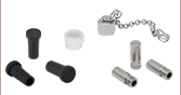
- Mounts for Connectors with Ø1.25 to Ø2.5 mm Ferrules
- Each Mount Requires Calibration with Reference Tool (Sold Separately Below)
- Locking V-Groove Design Ensures Stable, Repeatable Connection
The Locking V-Groove Mounts sold below can be swapped out for the Ø2.5 mm PC mount that comes standard with the CC6000 portable interferometer, allowing a wide variety of connectors to be tested with the CC6000 interferometer. For each insertion of a mount, a calibration must be performed using the corresponding reference tool sold below. Once this calibration is performed on a mount, the measurements can be accurately calculated for all connectors measured in that mount.
The table to the right provides a guide for choosing the right mount and reference tool for each type of connector. For more help, contact Tech Support.

 Zoom
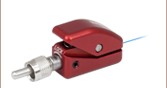
Zoom- Reference Tools for Calibrating Locking V-Groove Mounts
- Simple, Accurate Calibration Process
The Reference Tools sold below are designed to be used for calibration of the locking V-groove mounts used with the CC6000 interferometer (sold above). The RT250P reference tool is shipped with the CC6000 interferometer for use with the default CC250P mount. The table above serves as a guide for purchasing the appropriate reference tool for any additional mounts purchased. For more help, contact Tech Support.