Visual Scratch-Defect Fiber End Face Inspection System
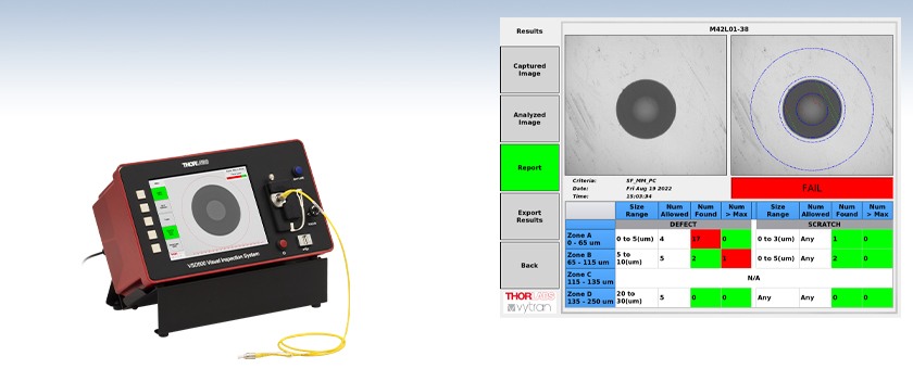
- Fiber End Face Inspection with 640X Magnification
- Adjustable Enhanced-Contrast Image Processing
- Auto Pass/Fail with IEC-Based Measurement Criteria
- 32 GB Storage with 4 USB Ports for Drive, Keyboard,
Mouse, and/or Barcode Scanner
Pass/Fail Limit Regions Streamline Production Line Integration
(Refer to the Software Tab for Details)
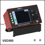
VSD500
Visual Scratch Defect
Inspection System
(Patch Cable
Not Included)

Please Wait
| VSD500 Specifications | |
|---|---|
| Optical Magnification | 640X |
| Field of View (W x H) | 208 µm x 180 µm |
| Lateral Resolution | 0.3 µm |
| Light Source | 450 nm LED |
| Integrated Display | 8", 1024 x 768 px, IPS LCD |
| Internal Storage | 32 GB Solid State Drive |
| Included Power Supply | DS12 |
| Dimensions (W x H x D) | 12.34" x 7.06" x 6.3" (313.4 mm x 179.4 mm x 153.2 mm) |
| Mass (Weight) | 2 kg (4.4 lbs) |
Features
- Critically Examine Fiber Polish Quality Prior to Using GL16 or CC6000 Interferometers
- Optimized for Fibers with Ø125 μm Cladding*
- Visual Inspection with Adjustable Contrast Enhancement
- Automatic Pass/Fail Reporting with Customizable Defect Size/Count Criteria
- Fiber Connector Mounts with Manual X/Y Adjustments and Z-Focus
- System Includes Two Fiber Mounts (Additional Mounts Sold Separately Below):
- VSD125P: Ø1.25 mm Ferrule LC Connectors
- VSD250P: Ø2.50 mm Ferrule FC/PC, SC, & ST®† Connectors
- 8" Built-In Display (4:3), External Monitor Output, and Tilt Stand
- Four USB Ports for Data Export, Keyboard, Mouse, and/or Barcode Scanner
The VSD500 Visual Scratch and Defect Detection System enables users to examine the end face of fiber connectors for permanent defects (such as scratches, cracks, and pits) and transient defects such as contaminants (dirt, oils, water, and cleaning solvent residues), complementing the interferometric inspection of the fiber end face geometry provided by our CC6000 and GL16 interferometers. For example, automatic inspections can be configured with initial criteria that are tailored to verify the removal of epoxy and chips caused by cleaving, while subsequent criteria may ensure the removal of scratches or pits from the fiber and clear delineation of epoxy and cladding.
Operation
Visual end face inspection occurs between each polishing step of a fiber optic cable manufacturing process. With a 450 nm LED to illuminate the fiber end face, the VSD500 system provides clear images of the fiber core and surrounding cladding at 640X magnification on its integrated 8" LCD. The displayed image can also be duplicated onto an external monitor using the port on rear of the device which accepts an HDMI‡ cable. The system should not be used to inspect a fiber connected to an active light source; light sources must be disconnected or turned off prior to fiber inspection.
Click to Enlarge
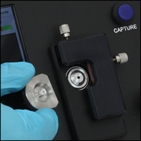
The fiber mounts are magnetically retained in the XY offset fixture.
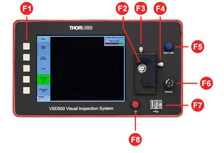
The VSD500 includes the VSD125P mount for LC connectors (Ø1.25 mm PC ferrules) and the VSD250P mount for FC/PC, SC, & ST connectors (Ø2.50 mm PC ferrules). A variety of additional mounts are available separately below. The chosen mount is magnetically retained on the front panel and two knobs adjust its offset in the X and Y axes. A knob to the lower right (when the system is oriented as shown in the image above) adjusts the image focus.
Once the fiber is centered and focused, the image can be captured, analyzed, and a pass/fail report can be generated using customizable pass/fail criteria provided by the user. The criteria include maximum scratch and defect size as well as quantity. Captured images and reports are automatically saved to the internal memory; these files can then be downloaded to a USB drive. Four USB ports on the front and rear provide compatibility with USB drives for data export or input devices such as a keyboard, mouse, and/or barcode scanner.
The system can be operated with the fiber holder on the left or the right side, simply by flipping the entire unit to the desired orientation. When changing the orientation, the power must be cycled in order for the User Inteface to display correctly.
*The VSD500 is optimized for SMF-28 type fibers, as well as other fibers with Ø125 µm claddings. Custom units that can accommodate maximum cladding diameters up to Ø200 µm are available, depending upon the published TIA or IEC test standards of the fiber; please contact Tech Support for details.
†ST® is a registered trademark of Lucent Technologies, Inc.
‡HDMI is a trademark or registered trademark of HDMI Licensing Administrator, Inc. The use of such trademark by Thorlabs does not constitute or imply any affiliation with or endorsement or sponsorship by such trademark owner.
The VSD500 Visual Scratch Defect Inspection System features a measurement software program that is fully integrated into the system. The intuitive controls and customization options ensure that it is easy to use right out of the box while also providing sufficient flexibility to accommodate many user requirements during the measurement process. The VSD500 system can be controlled via the buttons on the front of the device or using a keyboard or mouse peripheral via the USB 2.0 ports located on the front and at the rear of the system. Image captures in BMP, PNG, or JPEG formats and reports in PDF format can be exported to a USB drive connected to one of the USB ports; a text summary of all past analyses can also be exported in MySQL format.
Click to Enlarge
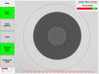
Overlay Tools
This mode provides software assisted fiber centering and end face focusing, both of which are needed prior to activating an inspection.
Click to Enlarge
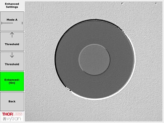
Image Enhancements (Mode A)
The user has the ability to select from and configure two types of enhancement by applying real-time post-processing to the image captured by the camera. Mode A improves visibility of end face artifacts by creating an impression of depth.
Click to Enlarge
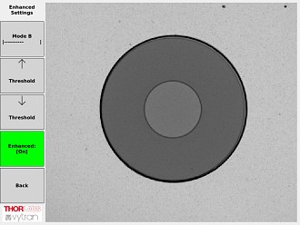
Image Enhancements (Mode B)
Mode B enhances image contrast. The processing threshold can be altered for either image enhancement mode. The enhancements have no effect on the automated inspection.
Click to Enlarge
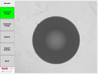
Captured Image
Pressing the Capture button on the front panel acquires a camera image, which can be used for automated artifact (scratch and defect) detection.
Click to Enlarge
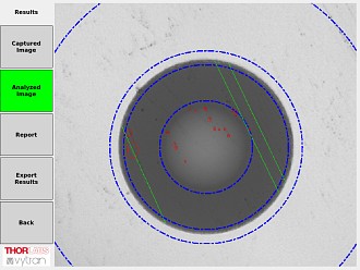
Analyzed Image
This screen shows the captured image with an overlay depicting the detected end face artifacts. The blue circles depict the chosen zone diameters to be analyzed. The green lines highlight detected scratches that are larger than the threshold and the red circles indicate defects.
Click to Enlarge
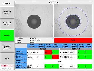
Report Screen
The report screen presents criteria details, inspection results, and Pass/Fail status. Click here for a sample report.
Click to Enlarge
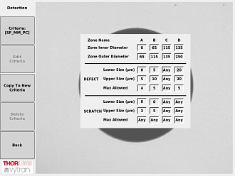
Detection Pass/Fail Criteria
Performing Pass/Fail testing requires prior selection of a set of criteria to be applied. The VSD500 system includes a standard set of criteria for common connector types, as defined by the applicable IEC61300-3-35 specification.
Click to Enlarge
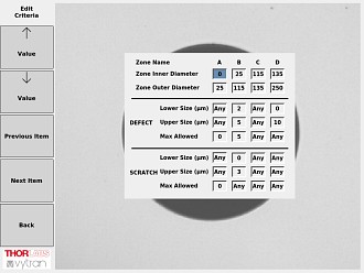
Custom Criteria
The factory-supplied criteria cannot be modified, but existing criteria can be copied and used as a starting point to create editable, custom criteria. A keyboard and mouse can be attached to speed up the editing process.
Click to Enlarge
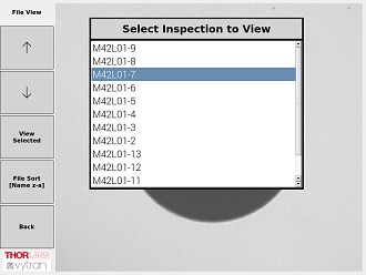
Storage Menus
Stored inspection reports can be viewed, deleted, or exported.
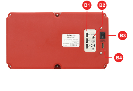
Front and Back Panels
Click to Enlarge
Front Panel
Click to Enlarge
Back Panel
| Front Panel | |
|---|---|
| Callout | Description |
| F1 | Menu Buttons |
| F2 | Slot for Connector Mount |
| F3 | Mount Y-Position Adjuster |
| F4 | Mount X-Position Adjuster |
| F5 | Capture Button |
| F6 | Image Focus Adjuster |
| F7 | USB 2.0 Type B Port |
| F8 | Power Button |
| Back Panel | |
|---|---|
| Callout | Description |
| B1 | USB 2.0 Type B Ports |
| B2 | +12 VDC Power Input |
| B3 | Power Switch |
| B4 | External Monitor Port (Accepts HDMIa Cable) |
| Posted Comments: | |
user
(posted 2023-12-27 08:13:12.86) Does this unit inspect and perform pass fail per the IEC -61300-3-35 standard? jpolaris
(posted 2023-12-27 06:52:08.0) Thank you for contacting Thorlabs. Yes, VSD500 includes a standard set of Pass/Fail criteria for common connector types, as defined by the applicable IEC61300-3-35 specification. |

Components Included
- Scratch Defect Measurement System
- Mount for LC Connectors
- Mount for FC/PC, SC, & ST Connectors
- Tilt Stand
- DS12 Power Supply
- Region-Specific Power Cord
- Operation Manual
Optional Purchases (Available Below)
- Additional or Replacement Mounts
- Manual and Automatic Inspection of Fiber End Face Scratches and Defects
- Integrated Scan and Data Management Software
- Two Fiber Mounts Included (Additional Mounts Available Separately Below)
- VSD125P: Ø1.25 mm Ferrule LC Connectors
- VSD250P: Ø2.50 mm Ferrule FC/PC, SC, & ST® Connectors
- Tilt Stand Included
The VSD500 Automatic Visual Scratch Defect Measurement system provides all the necessary components for fiber end face visual inspection integrated into a compact housing with an 8" LCD for local control. The software user interface is designed to provide a high degree of customizability over manual and automatic testing and report export options.
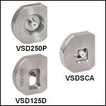
The VSD125P and VSD250P fiber connector mounts are included; other mounts can be purchased separately below. Each mount is retained magnetically in the slot on the front of the inspection system.

| Item # | Compatible Connector Type |
|---|---|
| VSD125P | Ø1.25 mm Ferrule LC Connectors |
| VSD250P | Ø2.50 mm Ferrule FC/PC, SC, & ST Connectors |
| VSDFCA | Ø2.50 mm Ferrule FC/APC Connectors |
| VSDSMA | SMA Connectors |
| VSDLCA | Ø1.25 mm Ferrule LC/APC Connectors |
| VSDSCA | Ø2.50 mm Ferrule SC/APC Connectors |
| VSDMT | MT Connectors |
| VSDMTA | MT/APC Connectors |
| VSD125D | LC/PC Duplex & Ø1.25 mm PC VSFF Duplex Connectors |
- Replacement and Additional Fiber Connector Mounts
- Magnetically Retained in VSD500 System for Easy Insertion and Removal
- VSD125P and VSD250P Mounts Included with VSD500 System
These fiber connector mounts provide compatibility with additional fiber patch cables, allowing a wide variety of connectors to be tested with the VSD500 Inspection System. The table to the right summarizes the connector compatibility for each mount. For assistance selecting a mount, contact Tech Support.
 Products Home


 Zoom
Zoom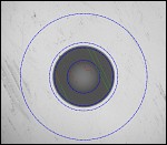
 Visual Scratch & Defect Inspection System