DC Block Electrical Filters, Coaxial

- Passive DC Block Filters
- Terminates Directly into High-Impedance Test Equipment
- DC Block Filter with 1 dB Cutoff of >1 Hz
- Mains Hum Filter for 50 - 60 Hz and 100 - 120 Hz Suppression
EF500
>1 Hz DC Block Filter
EF599
50 - 60 Hz Mains Hum Filter with DC Block
Application Idea
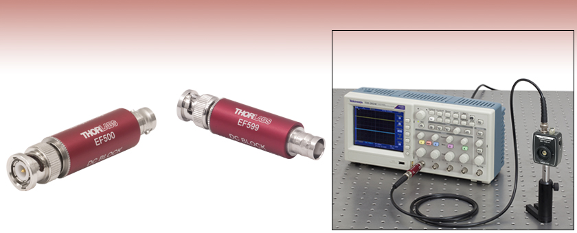
EF500 Used in Conjunction with a High-Impedance Oscilloscope and Amplified Photodetector

Please Wait

Click to Enlarge
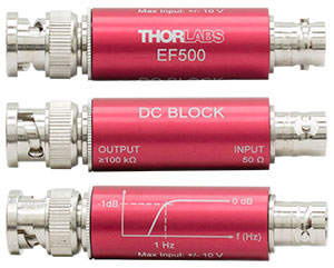
Figure 1.1 Each EF500 Series coaxial filter has a male and female BNC connector. It is engraved with the part number, the type of filter, the passband range, and the response curve (the EF599 displays the mains hum suppression values instead of the curve).
| Electrical Filters Selection Guide |
|---|
| Low-Pass Electrical Filters |
| High-Pass Electrical Filters |
| DC Block and Mains Hum Electrical Filters |
| DC Block Filter for RF |
Features
- Butterworth DC Block Filter Design
- With and Without Mains Hum Suppression
- Can be Driven by Any 50 Ω Load
- Designed to be Terminated into High-Impedance Equipment
- No External Power Supply Required
Thorlabs' Passive Electrical Filters are feedthrough BNC filters that allow the user to filter unwanted signals and noise. These DC block filters are designed to be driven by a low-impedance source and terminated directly into high-impedance equipment. Examples of typical 50 Ω (low-impedance) sources are Thorlabs' amplified photodetectors, while examples of high-impedance equipment include 1 MΩ oscilloscope terminals, DAQ boards, and 100 kΩ op-amp inputs. This page contains our DC block electrical filters. Thorlabs also offers low-pass and high-pass electrical filters, as well as a DC block filter for RF with SMA connectors.
These are passive filters; therefore, no power supply is needed to run these devices. Additionally, they will not display any of the intermodulation distortions that are often observed when using active filters. Passive filters also have lower noise floors and lower thermal emission than their active counterparts, giving these filters higher signal-to-noise capabilities. Each filter is engraved with the part number, passband range, input/output impedance values, and a frequency response curve.
DC Block Filters
These DC Block Filters are designed specifically to block out DC and very low frequency noise, allowing most of the signal through to the output. This large passband is advantageous when it is necessary to analyze or compare signals that contain a significant DC offset. The EF500 is a 1st order Butterworth filter designed to attenuate signals with sub-Hz frequencies. Perfect for removing unwanted DC biases, this device has excellent transmission at higher frequencies.
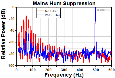
DC offsets are not the only problem to plague signal acquisition and analysis. Most often, noise from the mains electricity becomes written onto a signal. This phenomenon is known as mains hum and manifests itself with a fundamental frequency of 50 to 60 Hz. Spikes at the fundamental, second harmonic (100 Hz to 120 Hz), and third harmonic (150 Hz to 180 Hz) are the most common source of mains hum noise. The EF599, a 2nd order Butterworth filter, is a DC block filter specifically designed to filter out noise caused by mains hum. This filter provides excellent suppression through 400 Hz (3 dB, nominal) for attenuation of mains hum noise at its fundamental frequency and at higher harmonics.
Coaxial Design
The EF500 series filters are coaxial and feature a cylindrical design with a male and female BNC connector. This allows the filter to be directly attached to a device, such as an oscilloscope (see image above).
| Posted Comments: | |
Eric Oseassen
(posted 2024-02-12 21:48:28.607) QUESTION 1 - is the EF5500 DC Block polarized? In other words does it matter which direction the BNC ports are connected +/- or -/+
QUESTION 2 - i will be using this to block DC voltages in a baseband RF system which has a nominal impedance of 50 Ohms, how will this impact the performance cdolbashian
(posted 2024-03-05 02:28:07.0) Thank you for reaching out to us with this inquiry. The polarity in which you use this device matters, and to clarify I have contacted you directly. Regarding termination, these are designed to be used with Hi-Z devices, and we specify above on the product page that the performance will change when used with a 50Ohm impedence though we do not characterize it explicitly as that is not the design intent for these devices. Collin Bruce
(posted 2024-01-05 15:40:59.737) I think that a wider bandwidth version of the EF599 would be attractive to users of digital audio systems. Perhaps extending the top of the passband to 750khz or even 1mhz, like the EF507 or EF517. SPDIF digital audio, as you know, requires 1mhz to 100mhz bandwidth, but performance suffers greatly with interference outside of those frequencies.
My reading of the EF507 & EF517 is that they do *not* provide absolute/guaranteed DC blocking.
Ideally, 75r version would be preferable, but a 50r version would not be the end of the world. Thank you! ksosnowski
(posted 2024-01-08 10:34:56.0) Hello Collin, thanks for reaching out to Thorlabs. EF507, EF517, and our other highpass filters are still DC-blocking, however EF599 is one we designed to essentially only block DC and mains frequencies as common noise sources. 50 Ohm input impedance was chosen for our filter series as it matches the impedance in many common photodiode/amplifiers systems we see used. Unfortunately, it is quite a process to find different components that provide the exact passband necessary while maintaining good blocking performance and we do not plan on redesigning any of the electrical filters at this time. José de Oliva Rubio
(posted 2023-05-24 09:16:36.573) Dear Thorlabs team,
We need to block the DC part of an amplified photodiode receiver output. We need a bandpass that begins in the tenths of hertzs and reaches the few kilohertz band. Your EF500 could suit us, the problem is that in the specifications section of the web the frequency response of the EF500 is only plot up to 100 Hz or so. Could you provide us with a wider measurement of the transmission response of the component? Even though it might not be specifications strictly speaking, but typical response.
I'm looking forward to receiveing your feedback.
José cdolbashian
(posted 2023-06-01 02:19:35.0) Thank you for reaching out to us with this inquiry. You are indeed correct that this has not been tested formally on our end. I have contacted you directly in order to find a way to supply you with these extended data. xiaowei.feng
(posted 2017-08-11 14:45:14.933) Hi,
could you provide a SPICE model of your product EF500 so that we can simulate it?
Best Regards
Xiaowei tfrisch
(posted 2017-08-28 04:10:13.0) Hello, thank you for contacting Thorlabs. While we don't have SPICE models for these filters, we will reach out to you to discuss the performance. pbow027
(posted 2017-08-03 09:52:41.737) Hi, I need to block the DC component going into an RF electrical spectrum analyser. Both the DC block filter and high-pass filter seem good, but which will be better if I need to see my spectrum at GHz repetition rates? Thank you :) Patrick tfrisch
(posted 2017-08-28 02:55:37.0) Hello, thank you for contacting Thorlabs. While these filters are not designed for use from DC up to GHz regimes, we may be able to provide a filter with a suitable cut-on wavelength. I will reach out to you directly about your application. hj
(posted 2017-08-01 13:39:56.647) Hi, I just have one question.
The specification of this product says the input voltage (Maximum) is 10 V.
If I want to filter out DC 20 V in my setup, can I just connect two of these filters (EF599) in series?
Thanks in advance.
/Hoon nbayconich
(posted 2017-08-04 05:45:24.0) Thank you for contacting Thorlabs. Stacking two EF599 filters will not improve compliance voltage. The voltage will not be distributed as in a simple series circuit. I will contact you directly with more information. rayfang
(posted 2016-08-27 20:54:51.12) Hi there,
I would like to use the EF500 to protect a spectrum analyser that has a 50 ohm input. Can I connect the 50 ohm source termination to the spectrum analyser, and the high impedance load to the DUT instead? It is a passive device, so I believe signal transmission should be reciprocal. Kindly advise.
Thanks.
Ray tfrisch
(posted 2016-09-07 09:44:49.0) Hello Ray. Thank you for contacting Thorlabs. EF500 does use passive components. I'll contact you directly about how the performance might be affected, specifically through change in the cut-on and back reflections. |


Click to Enlarge
Figure G1.1 This graph shows a signal taken on an oscilloscope with (blue trace) and without (red trace) using a filter. The observed phase shift is introduced by the filter.
The coaxial package of these filters offers one male and one female BNC connector.
| Item #a | EF500 | EF599 |
|---|---|---|
| 1 dB Passband Windowb (Nominal) | >1 Hz | >650 Hz |
| 3 dB Rejection (Nominal) | <0.3 Hz | <400 Hz |
| 40 dB Rejection (Nominal) | <3 mHz | - |
| 80 dB Rejection (Nominal) | <30 µHz | - |
| 50 - 60 Hz Rejection (Nominal) | - | 27 dB |
| 100 - 120 Hz Rejection (Nominal) | - | 19 dB |
| Frequency Response Curve (Click for Graph) |
Raw Data |
Raw Data |
| Source Impedance (Typical) | 50 Ω | |
| Load Impedance (Typical)c | ≥100 kΩ | |
| Input Voltage (Maximum) | ±10 V | |
| Storage Temperature | -20 to 70 °C | |
 Products Home


 Zoom
Zoom
 DC Block Electrical Filters