 Products Home
20 mA - 4 A Laser Diode Drivers
- Constant Current or Constant Power Driving of Laser Diodes
- Extremely Low Noise
- Compatible with all Laser Diode & Photodiode Polarities
- Current Limit and Interlock for Laser Diode Protection
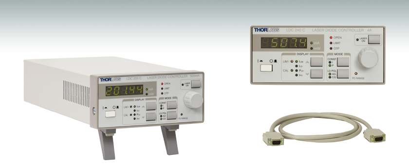
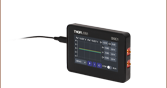
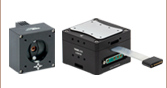
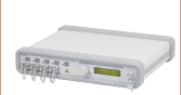
LDC205C
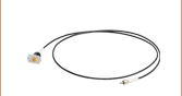
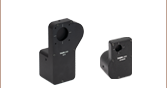
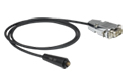
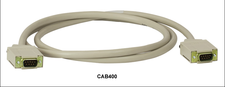
CAB400
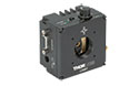
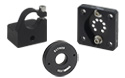
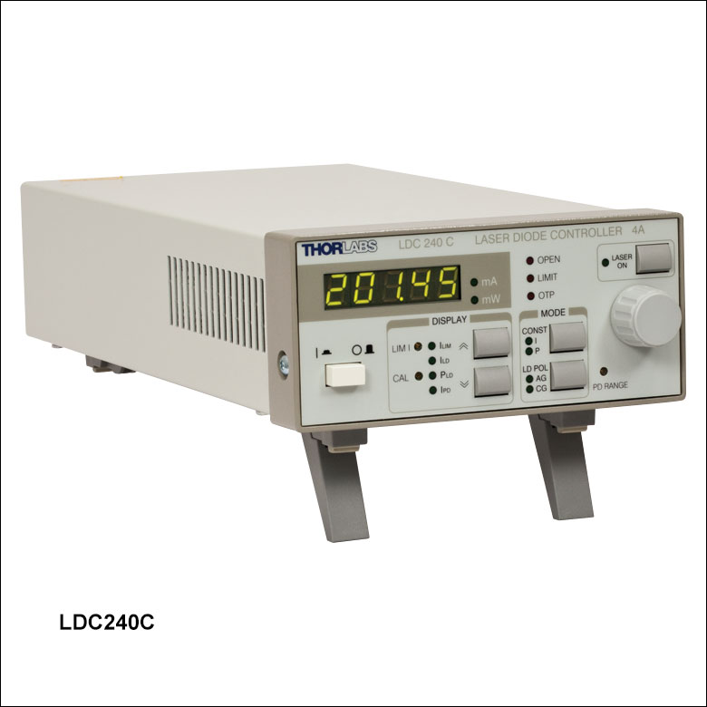
LDC240C Front


Please Wait
Features
- Extremely Low Noise (LDC201CU 0.2 μA)
- 5-Digit LED Display
- Analog Control Input and Output
- Reliable Laser Diode Protection
- Operates With All Polarities of Laser Diode and Photodiode
- Seven Models With Laser Current Ranges From 20 mA to 4 A
- Certificate of Calibration and Test Report Included
The laser diode controllers in the LDC200C series all provide features that ensure outstanding performance. There are seven models with different current ranges, each configured to provide optimal performance for their particular application. Every unit ships with a certificate of calibration as well as a full test report. Please refer to the Specs tab and the Selection Guide tab for an overview of the products.
Thorlabs recommends recalibrating these drivers every 24 months and offers a factory recalibration service. To order this service, scroll to the bottom of the page and select Item # CAL-LDC2.
Modes
With the laser diode controllers of the LDC200C series, laser diodes can be driven in constant current (CC) or constant power (CP) mode. All laser diode and photodiode configuration types are supported. The laser diode is always driven with respect to ground. In comparison to driver designs that require a floating ground, this grounded operation of the laser diode offers advantages regarding noise, transient suppression, and stability.
Constant Current
In CC mode, the current to the laser is held precisely at the prescribed level. This mode is used when the lowest noise and highest response speed is required. Most applications in this mode require stabilizing the temperature as well. We offer two lines of temperature controllers, the TED200C for up to 12 W and the TED4015 for up to 225 W.
Constant Power
In CP mode, the internal photodiode integrated into most laser diode packages is used to actively stabilize the laser's output power, which is adjusted by a feedback circuit. An adjustment of the full scale photodiode current in CP mode is provided in order to compensate for the differences in the photodiode currents between different laser diodes.
Controller Use
Intuitive User-Friendly Operation
Independent of the selected operating mode, the 5-digit LED display can show the laser current, the photodiode monitor current, or laser current limit. It can also display the optical power (in mW). The power readout can be calibrated to the responsivity of the monitor photodiode by adjusting a front panel trim potentiometer. In many applications, the aforementioned benefits eliminate the need for a separate optical power meter.
Additional Rear Panel Controls
Available for use at the rear of the unit are: a modulation input for laser current or power (which can be used to pulse the laser diode output), a control output proportional to the laser current, and a TTL input for remote laser on/off.
Protection Features
Current Limit
A precisely adjustable current limit ensures that the maximum laser current cannot be exceeded. Thorlabs has intentionally provided limited access to this feature to prevent accidental adjustment. An attempt to increase the laser drive current above the pre-set limit will result in a visible and short audible indicator. Even when utilizing the external modulation feature, the current limit set-point cannot be exceeded.
Current Source
If the connection between the current source and laser diode is interrupted, the current source automatically switches off the current output. The open current circuit condition is indicated by the LED "OPEN" and a short acoustic warning. The separate laser ON key switches the laser current on and off. When switched off, an electronic switch within the LDC200C short circuits the laser diode for added protection. After being switched on, a soft start ensures a slow increase of the laser current without voltage peaks. Even in the case of line failure, the laser current remains transient-free. Voltage peaks on the AC line are effectively suppressed by electrical filters, shielding of the transformer, and careful grounding of the chassis.
Connection Cables
A CAB400 is required to connect the LDC200C series laser diode controllers to a Thorlabs' Laser Diode Mount. One cable is included with each laser diode controller, it has a length of 1.5 m. Additional cables can be ordered below.
| Laser Diode Accessory Selection Guide | |||||
|---|---|---|---|---|---|
| Temperature Controlled Mounts | Passive Mounts | Passive Mounts with Collimation Package | Strain Relief Cables | Diode Sockets | Other Controllers |
 |
 |
 |
 |
 |
 |
| Item # | LDC200CV | LDC201CU | LDC202C | LDC205C | LDC210C | LDC220C | LDC240C |
|---|---|---|---|---|---|---|---|
| Current Control (Constant Current Mode) | |||||||
| Control Range | 0 to ±20 mA | 0 to ±100 mA | 0 to ±200 mA | 0 to ±500 mA | 0 to ±1 A | 0 to ±2 A | 0 to ±4 A |
| Compliance Voltage | >6 V | >5 V | >10 V | >10 V | >10 V | >4 V | >5 V |
| Resolution | 1.0 µA | 10 µA | 10 µA | 10 µA | 100 µA | 100 µA | 100 µA |
| Accuracy | ±20 µA | ±50 µA | ±100 µA | ±0.5 mA | ±1.0 mA | ±2.0 mA | ±4.0 mA |
| Noise Without Ripplea | <1.0 µA | <0.2 µA | <1.5 µA | <3 µA | <5 µA | <15 µA | <50 µA |
| Rippleb | <0.5 µA | <0.5 µA | <1.5 µA | <2 µA | <3 µA | <5 µA | <8 µA |
| Transients (Typ.) | <10 µA | <10 µA | <0.2 mA | <0.5 mA | <1 mA | <2 mA | <4 mA |
| Drift, 24 hoursc | <1 µA | <2 µA | <3 µA | <10 µA | <20 µA | <100 µA | <200 µA |
| Temperature Coefficient | <50 ppm/°C | ||||||
| Current Limit | |||||||
| Setting Range | 0 to >20 mA | 0 to >100 mA | 0 to >200 mA | 0 to >500 mA | 0 to >1 A | 0 to >2 A | 0 to >4 A |
| Resolution | 1 µA | 10 µA | 10 µA | 10 µA | 100 µA | 100 µA | 100 µA |
| Accuracy | ±50 µA | ±200 µA | ±500 µA | ±1.5 mA | ±2.5 mA | ±5 mA | ±10 mA |
| Power Control (Constant Power Mode) | |||||||
| Photocurrent Control Range | 5 µA to 2 mA | 25 µA to 10 mA | 50 µA to 20 mA | ||||
| Photocurrent Resolution | 0.1 µA | 1 µA | 1 µA | ||||
| Photocurrent Accuracy | ±2 µA | ±10 µA | ±20 µA | ||||
| Analog Modulation Input | |||||||
| Input Resistance | 10 kΩ | ||||||
| Small Signal 3 dB Bandwidth, CC Mode |
DC to 100 kHz | DC to 0.2 kHz | DC to 250 kHz | DC to 150 kHz | DC to 100 kHz | DC to 50 kHz | DC to 30 kHz |
| Modulation Coefficient, CC Mode |
2 mA/V ± 5% | 10 mA/V ± 5% | 20 mA/V ± 5% | 50 mA/V ± 5% | 100 mA/V ± 5% | 200 mA/V ± 5% | 400 mA/V ± 5% |
| Modulation Coefficient, CP Mode | 0.2 mA/V ± 5% | 1 mA/V ± 5% | 2 mA/V ± 5% | ||||
| Laser Current Monitor Output | |||||||
| Load Resistance | >10 kΩ | ||||||
| Transmission Coefficient | 500 V/A ± 5% | 100 V/A ± 5% | 50 V/A ± 5% | 20 V/A ± 5% | 10 V/A ± 5% | 5 V/A ± 5% | 2.5 V/A ± 5% |
| General Data | |||||||
| Safety Features | Interlock, Laser Current Limit, Soft Start, Short Circuit when Laser Off, Open Circuit Detection, Over Temperature Protection |
||||||
| Display | LED, 5 Digits | ||||||
| Connector for Laser, Photodiode, Interlock & Laser On Signal |
9-pin D-Sub Jack | ||||||
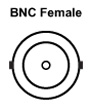
| Connectors for Control Input / Output |
BNC | ||||||
| Chassis Ground Connector | 4 mm Banana Jack | ||||||
| Line Voltage / Frequency | 100 V, 115 V, 230 V +15% –10% each / 50 to 60 Hz | ||||||
| Maximum Power Consumption | 20 VA | 20 VA | 25 VA | 30 VA | 40 VA | 60 VA | 100 VA |
| Mains Supply Overvoltage | Category II (Cat II) | ||||||
| Operating Temperature | 0 to 40 °C | ||||||
| Storage Temperature | -40 to 70 °C | ||||||
| Relative Humidity | Max. 80% Up to 31 °C, Decreasing to 50% at 40 °C | ||||||
| Pollution Degree (Indoor Use Only) | 2 | ||||||
| Operation Altitude | <2000 m | ||||||
| Warm-up Time for Rated Accuracy |
10 min | ||||||
| Weight | <3.1 kg | <3.3 kg | |||||
| Dimensions (W X H X D) without Operating Elements |
146 mm x 66 mm x 290 mm | ||||||
| Dimensions (W X H X D) with Operating Elements |
146 mm x 77 mm x 320 mm | ||||||
LDC Front Panel

| Callout | Connection | Callout | Connection |
|---|---|---|---|
| 1 | 5-Digit LED Display | 9 | Display Indicators |
| 2 | Display Units | 10 | Up/Down Display Select |
| 3 | Interlock Indicators | 11 | Diode Polarization Indicator |
| 4 | Laser Status Indicator | ||
| 5 | Laser Current On/Off Switch | 12 | Output Mode Indicator |
| 6 | Display Adjustment Knob | 13 | Diode Polarization Select |
| 7 | Supply Power Switch | 14 | Output Mode Select |
| 8 | Current Limit and Power Calibration Pots | 15 | Photodiode Current Range Pot |
LDC Back Panel
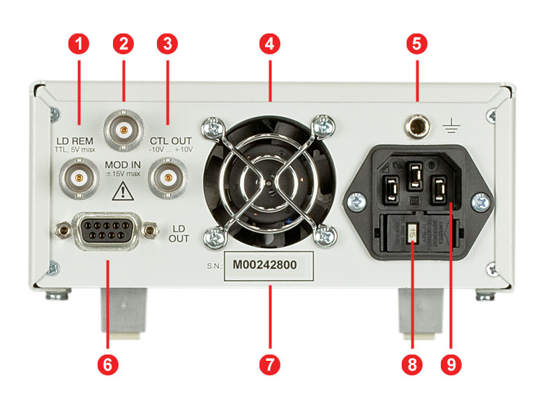
| Callout | Connection | Callout | Connection |
|---|---|---|---|
| 1 | TTL Input "LD REM" 0 to 5 V | 6 | Connector "LD OUT" for LD, PD, Interlock, & Status LED |
| 2 | Modulation Input / Analog Control Input "MOD IN", -10 to +10 V | 7 | Serial Number of the Unit |
| 3 | Analog Control Output "CTL OUT", -10 to +10 V | 8 | Indicator / Switch for Line Voltage (Included in Fuse Holder) |
| 4 | Cooling Fan | ||
| 5 | 4 mm Banana Jack for Chassis Ground | 9 | Power Connector and Fuse Holder |
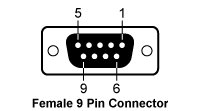
| Pin | Connection | Pin | Connection |
|---|---|---|---|
| 1 | Interlock and Status LASER ON/OFF | 6 | Not Connected |
| 2 | Photodiode Cathode | 7 | Laser Diode Cathode (with Polarity Anode Grounded - AG) |
| 3 | Laser Diode Ground | 8 | Laser Diode Anode (with Polarity Cathode Grounded - CG) |
| 4 | Photodiode Anode | ||
| 5 | Ground for Pin 1 | 9 | Not Connected |
Laser Diode Connector
Laser Diode Remote*
*TTL Input
(0...+5 V)
Modulation Input**
**Analog Control Input
(-10 V ...10V)
Control Output***
***Analog Control Output
(0 ...±10 V)
Chassis Ground

| Posted Comments: | |
Geoffroy Granger
(posted 2024-11-08 08:29:56.043) Hi, we have some problem on your LDC240C current source. The fuse is burn at the first switch on. Can you give us some suggestion? jjadvani
(posted 2024-11-08 07:26:25.0) Dear Geoffory, thank you for contacting Thorlabs. The problem you stated could be caused by an incorrect voltage setting on the back of the device. I will contact you personally to provide further help Young Soo Yu
(posted 2023-12-20 18:04:54.86) Hello, I'm using LDC205C to supply current to my laser diode(Eagleyard 671nm 15mW diode).
But I'm seeing some phenomena that I don't understand.
When I increase my current the diode seems to work well except for current range 50~60mA. (CC mode)
The current fluctuates very large(20~30mA fluctuation).
Do you have some technical suggestion about this?
Thank you hkarpenko
(posted 2023-12-20 07:01:06.0) Dear customer,
thank you for your feedback. In this case it would be necessary to check the laser diodes specifications, such as threshold current, max current, max voltage. Therefore I will contact you directly to discuss this issue in detail with you. Maeno Yuto
(posted 2023-06-09 14:55:10.673) If the current is increased to 850 mA with the laser output turned on, the internal lock will open at 850 mA. wskopalik
(posted 2023-06-14 07:42:39.0) Thank you very much for your feedback!
It is possible that the compliance voltage of the LDC220C is exceeded at this current. The larger the current which is applied to a laser diode, the larger the voltage at the diode will be. The LDC220C has a compliance voltage of a little above 4 V. So it is possible that this voltage limit is exceeded at 850 mA.
I will contact you directly so we can check the spec sheet of the diode to see if this could be the reason. Rajesh D
(posted 2022-07-14 11:13:46.36) Dear Thorlabs
We recently purchased a LDC20C but while making the fuses we broke the plastic retainers (below the 3pole power connector, R10) while pressing the fuse holder. Now, I am not able to open the fuse holder (R10) so can you please let me know some solution for this, do Thorlab will replace for the LDC205C. Thank you
Regards
Rajesh hkarpenko
(posted 2022-07-19 07:51:21.0) Thank you very much for your feedback. I will reach out to you directly to discuss this further with you. user
(posted 2022-04-08 23:24:15.467) Hi,
How can one measure phase noise and intensity noise of laser diodes from using LD driver LDC205C? How can one analyse noise characteristics of LDC205C?
thanks. soswald
(posted 2022-04-14 04:48:57.0) Dear Customer,
thank you for your feedback. I have reached out to you directly to discuss your application in more detail. Rebecca Chen
(posted 2021-11-03 08:00:26.923) Hello. I am using the controller LDC220C to drive a laser diode. I wonder if I can give an input of a square wave at 12 kHz (50% duty cycle) to the analog modulation input ? Thanks a lot ! wskopalik
(posted 2021-11-09 09:06:45.0) Thank you very much for your inquiry!
The analog modulation input of the LDC220C is specified with a small signal 3dB bandwidth of DC to 50 kHz. For a square wave a rule of thumb is to have at least a factor of 10 more bandwidth than the modulation frequency to keep a good square shape. So square waves with 12 kHz are probably a bit too much for the LDC220C.
If you already have an LDC220C, you can however try to apply a 12 kHz signal. The edges of the square waves will not be perfect and a bit blurred but depending on the requirements it could still be good enough.
I will also contact you to provide further assistance. user
(posted 2021-02-24 20:30:05.52) I am using LDC205C, but I cannot adjust the I_LIM (current limit). It is always 100 mA.
Is there anything I should pay attention to?
How can I adjust the current limit?
Thanks a lot! wskopalik
(posted 2021-02-25 04:30:05.0) Thank you very much for your inquiry!
The current limit can be adjusted using the potentiometer “LIM I” on the LDC205C. First, set the display to "ILIM" using the arrow buttons. It will then show the set current limit. Then use a screwdriver to set the desired current limit by turning the potentiometer "LIM I". It is the safest to switch the laser current off during the adjustment.
I will also contact you directly to provide further assistance. 青青 何
(posted 2020-12-14 21:27:33.05) 您好,请问一下使用索雷博专用夹具LM14S2 TYPE1情况下(供电激光器型号索雷博SLD1005S ), MODE中LD POL如何选择 MKiess
(posted 2020-12-15 05:24:38.0) Thank you very much for your inquiry. A member of the Chinese technical support team will contact you directly. user
(posted 2020-10-01 18:36:04.053) Hello, I am using the LD205C. Is there a way to measure the voltage applied to the LD when driving in current mode? (looks like there are voltage readout pins on CAB400, I'm wondering if these could be redirected to a voltmeter?) MKiess
(posted 2020-10-02 08:16:16.0) Hello, thank you very much for your inquiry. The LDC205C does not allow you to check the voltage via the 9-pin connector. The pins of the CAB400 are not connected on the LDC200 series. With the LDC4000 series controllers and the PRO8 laser diode current control modules you have the possibility to measure the laser voltage. Johanna T
(posted 2020-06-09 04:33:44.67) Hi, Is the LDC205C compatible with a LD with a floating anode (in a butterfly type 2 with bias T package)? nreusch
(posted 2020-06-15 03:46:26.0) Thank you for your inquiry. Yes, you can drive floating laser diodes with the drivers of our LDC series. As settings for the laser diode output configuration, you can either use AG or CG polarity. Please carefully check that the pin assignment of your diodes is compatible with the pins of the LDC driver that are shown in the Pin Diagram tab. wenzel.jakob
(posted 2017-11-28 19:28:38.723) Dear Thorlabs support, a minor question that wasn't clear to me from the documentation: do the LDC* controllers persist the current/regulation settings when they are powered off and turned on again at a later point? Or does the entire configuration have to be repeated each time? The same question also applies to your temperature controller TED200C. Thank you! swick
(posted 2017-12-01 03:34:43.0) This is a response from Sebastian at Thorlabs. Thank you very much for the inquiry. When nothing is changed at the control panel, the current limit, current set point and other settings will not vary when power cycling the LDC drivers. Same is valid for TED200C. v.lychagov
(posted 2017-11-22 16:35:56.917) Hi
I'm using LDC205C w/ TCLDM9. I wonder if it is possible to connect directly to PD output of a laser diode? I want to record and process signal from photodiode rather then monitoring it's current with LDC. mvonsivers
(posted 2017-11-27 09:19:18.0) This is a response from Moritz at Thorlabs. Thank you for your inquiry. To monitor the PD signal externally you would need a custom cable which is connected to pins 2 and 4 of the "LD Driver" connector on the TCLDM9 mount. I will contact you directly for further details. s.zhou
(posted 2017-08-16 12:06:09.48) Hi Thorlabs,
I am using a LDC202C current source in constant current mode, and find that the I_LD_SET changes over time. As I am using a function generator to control the current source, when I_LD_SET changes, the current output also changes. Could you explain me what is exactly the I_LD_SET and what will affect its value? I can't find much information about it on the manual.
Thanks. mvonsivers
(posted 2017-08-17 04:04:32.0) This is a response from Moritz at Thorlabs: Thank you for your inquiry. When modulating the current with an external voltage source, I_LD_SET is an offset value that can be changed using the control knob. I will contact you directly for further details. ltli
(posted 2017-08-14 13:03:35.617) Hi, we have some problem on your LDC240C current source. The current source was in normal use (~1.3A, connected to an AG laser diode) but suddenly generated a buzzer sound and stopped working in the last week. The current source has no output current and the LED display shows "-----" when selecting ILD. However, the display of ILIM is normal. Can you give us some suggestion? mvonsivers
(posted 2017-08-17 06:18:11.0) This is a response from Moritz at Thorlabs: Thank you for your inquiry. It would be best to send in the unit to us for inspection. You will be contacted by us for further information. artur.rackos
(posted 2017-05-12 11:15:17.12) Dear Thorlabs, is your laser diode driver LDC205C compatible with laser ’PLT5 520_B1_2_3’ with built-in photodiode? How can I connect ’PLT5 520_B1_2_3’ with photodiode in reverse bias mode? swick
(posted 2017-05-15 03:21:52.0) This is a response from Sebastian at Thorlabs. Thank you for the inquiry.
This Laserdiode is compatible to LDC205C and has Pin Style A (LD Anode and PD Cathode connected to Ground). If the Photodiode shall be operated with bias voltage, a battery can be connected in series to the Photodiode. You can find further information in the manual of LDC205C on page 12.
I will contact you directly to provide assistance. user
(posted 2017-03-29 22:39:34.45) Would it be possible to have a strain relief version of the CAB400? I like the SR9 cables a lot, but changing the diode drive to one with TEC meaning I have to give them up. The CAB400 in comparison is too rigid. swick
(posted 2017-03-31 03:06:09.0) This is a response from Sebastian at Thorlabs. Thank you very much for the feedback.
At the time we do not offer Strain Relief Cables for laserdiodes based on CAB400. We will internally discuss this idea. user
(posted 2016-10-11 13:48:19.68) Why is the current listed as ±? It doesn't make sense to me to be able to reverse the current. For one thing the LD won't function and can be damaged by reversing leads. In fact other LD drivers will switch off if you attempt to energize with reversed leads, which is a useful safety feature. Does this model have that feature? swick
(posted 2016-10-13 03:28:48.0) This is a response from Sebastian at Thorlabs. Thank you very much for your inquiry.
The ± is referred to the feature Anode Grounded (AG) and Cathode Grounded (CG). While keeping the Compliance Voltage positive the Electrical Current has to be positive for CG and negative for AG.
For LDC-Series if the laser diode was connected correctly but the polarity of the laser diode was selected wrong, an “OPEN” error will be indicated. After pressing "LASER ON" the LED "OPEN" extinguishes and the output can be switched on by pressing "LASER ON" again. kedves
(posted 2015-12-12 11:24:02.757) Dear Thorlabs, is your laser diode driver DC201CU compatible with your LED sources, e.g. LED631E? We need a very stable current driving for a LED and we have such a laser diode driver. I suppose we can use it, cannot we? Best regards shallwig
(posted 2015-12-14 05:10:02.0) This is a response from Stefan at Thorlabs. Thank you very much for your inquiry. The LDC201CU can deliver up to 100mA constant current at 5V compliance voltage. The LED631E can be driven up to 50mA (max rating) at typically 2.2V. You can find these information in the spec sheet of the Driver http://www.thorlabs.de/newgrouppage9.cfm?objectgroup_id=10&pn=LDC201CU and LED http://www.thorlabs.de/thorcat/16200/LED631E-SpecSheet.pdf You can use this driver in “constant current” mode to run the LED. There is no ready to use mount for these LEDs available, for correct connection please check the Pin assignment of CAB400 cable: http://www.thorlabs.de/newgrouppage9.cfm?objectgroup_id=10&pn=LDC201CU The Interlock Pin 1 and pin 5 must be connected externally by a short cut wire, by a circuit (total resistance <430 Ohm) : The current limit should be set at the ILim potentiometer to maximum 50mA. Please also take care of the soldering specifications which are mentioned in the LED spec sheet as well as correct pin assignment. I will contact you directly to check if there are any open questions. faisal_ipa3
(posted 2015-04-17 16:49:18.22) Hi, I am using Thorlabs LDC 205C and LM9LP. I would like to pulse signal on them. I am looking for external analog modulation for LDC 205C. Is that offered by Thorlabs? Thanks. shallwig
(posted 2015-04-20 02:21:55.0) This is a response from Stefan at Thorlabs. Thank you very much for your inquiry. Unfortunately we do not offer function generators so far. There are various options from other manufacturers, I will contact you directly to discuss your needs in detail. prax.jean.sebastien
(posted 2015-03-02 15:40:30.787) Dear Madam or Sir, I currently have an LDC210C and want to drive an FPL1009P laser diode on an LM14S2 mount. I would like the diode to deliver a pulse with a frequency of 10MHz. Can I achieve this with the external modulation input? Thank You. tschalk
(posted 2015-03-04 09:28:59.0) This is a response from Thomas at Thorlabs. Thank you very much for your inquiry. The bandwidth of the analog modulation input of the LDC210C is DC to 100kHz and a modulation of 10MHz is not possible. But the laser mount LM14S2 provides a RF modulation input (BIAS-T) for an external modulation up to 500MHz. You can find more detailed Information in the corresponding Manual at RF Modulation: http://www.thorlabs.de/thorcat/10600/LM14S2-Manual.pdf ferrari
(posted 2013-10-22 17:24:50.883) Dear Madam or Sir,
I am using an LDC202 to drive a diode laser, and I would like to protect the diode when the controller is not connected or not working using a shorting Reed relay. This relay would be driven with the 10mA current available through the interlock pins 1 and 5 while the laser is "on". To do this I would need a voltage of the order of 5V between pin 1 and 5, but instead I found about 2.3V. Is there a possibility to increase this voltage to about 5V.
Thank you,
Gabriele Ferrari tschalk
(posted 2013-10-24 06:13:00.0) This is a response from Thomas at Thorlabs. Thank you very much for your inquiry. The interlock is not designed to be used as an external signal. Because of the internal logic circuit its not possible to provide the signal you would need for your application. I will contact you directly with more detailed information. bdada
(posted 2012-05-17 15:38:00.0) Response from Buki at Thorlabs:
Thank you so much for your feedback and suggestion. We agree that it would be helpful to make the modulation bandwidth more visible, especially since these Laser Diode controllers look alike but have different modulation bandwidths.
We will look into offering an immediate and long term solution. Thank you again for sharing your thoughts. Please contact TechSupport@thorlabs.com if you would like to discuss this further. user
(posted 2012-05-16 17:20:10.0) Please consider printing the modulation bandwidth on the back panel next to the control input, this would save some of us from wasting valuable time. I was using your LDC201CU and didn't realize the BW was just 0.2 KHz as i was familar with the LDC202 which has a 250 KHz BW, silly me i just assumed they would be the same. jvigroux
(posted 2012-01-10 10:00:00.0) A response from Julien at Thorlabs: thank you for your inquiry! Yes the LDC200C series can be used also in pulsed operation when using the external modulation input. hautlutao
(posted 2012-01-10 15:54:47.0) Dear Mr. or Mrs.
Could the LDC laser diode driver driven laser diode operating in pulsed mode ? jvigroux
(posted 2011-12-13 12:23:00.0) A response from Julien at Thorlabs: Thank you for your feedback! We'll put the links to the required cables on this product page as well as on the product page of the TED200C. rsavioli
(posted 2011-12-13 10:44:09.0) Why don't you have any information pointing to the CAB400 and related interface cables on this page or any other LDC or TED pages, with the exception of the PRO8 stuff? I just spent 10 minutes looking for them and finally had to pull out a catalog. bdada
(posted 2011-10-03 09:23:00.0) Response from Buki at Thorlabs:
Thank you for so much your feedback. Our design engineers will look into this issue and we will contact you to discuss what you can do to improve the feel or performance of the knob. olsonaj
(posted 2011-10-02 10:30:21.0) Have had this controller for a couple years. An issue I've had is the front current control knob is very loose, and makes it hard to tune the current precisely (esp. important for manually current-tuning the wavelength of a diode laser). Also, at times the knob seems "loose" and the current will jump around between different values. Perhaps this is a faulty connection? On future designs I recommend a sturdier current control knob. bdada
(posted 2011-04-08 14:50:00.0) Response from Buki at Thorlabs to Emmanuel:
Thank you for your feedback, Emmanuel. We will contact you shortly to discuss your set up and verify the laser diode is connected properly to the driver. emmanuel.vanbrackel
(posted 2011-04-08 09:01:22.0) I have a big issue with this kind of driver. Up to now, I used a home-made driver that was built many years ago. Nevertheless, I needed a less noisy source, so I bought this. I tried to plug my laser diode (HL 6320G), following each documentation (of the diode, AG, following the pins correctly ; of the current controller, connecting the right pins to their right place, chose properly the polarity on the driver, set the limit for the current to 70 mA, put the knob to the left,...) : and when I push "laser on", when no current, its ok. But as soon as I get 0.1 mA, the open lights up, and no current anymore. I tried other cables configurations, verified that my diode works (with the old controller).
Whats wrong ?
Has anyone experienced that ?
Bests jhartmann
(posted 2009-08-13 12:52:30.0) A response from Juergen at Thorlabs to joonggun.ha: This error message indicates a hardware failure. From experience it is known to us, that in 99% of such cases the reason for this failure is operation of the item at 230V AC while it was set to 100/115V AC. Of course, mains fuse blows, however during fuses reaction time damages to electronic circuitry may happen.
After replacement of mains fuse and setting to correct AC, the unit switches on, but indicates only "Err.05", no operation is possible.
The unit must be returned for repair to Thorlabs, this repair is NOT covered by warranty as the unit has been used inappropriate: We put an eyecatching yellow sticker accross the AC power connector on the rear panel, alerting the operator "Use correct voltage setting and fuse - see manual". So prior to apply AC voltage, this sticker must be removed.
Please contact the Sales office, from where it has been purchased, for return instructions. joonggun.ha
(posted 2009-08-12 22:21:52.0) We have a litter LDC202C LD Controller.
Today, one controller displyed an error message and did not work.
The message is "Err.05".
I recheck operation manual but could not find this error message. What is the problem?
Please, answer ASAP. juergen
(posted 2008-07-23 10:49:09.0) Hi Ina, Thank you for your feedback. Manual and web specs are correct - LDC201CU is an ultra low noise driver. This is achieved by a low pass filter on the current output. Due this LPF, the max. modulation frequency in CC mode is 200Hz (-3dB, small signal) In VOL19, p.419, spec table, 200kHz is stated, which is wrong. We will correct that. Juergen Hartmann ina.kinski
(posted 2008-07-18 01:50:28.0) Hi, there is a typo both on this webpage and the operation manual that comes with this laser diode controller (p. 37):
The small signal 3dB bandwidth (cc mode) goes up to 200kHz, not 200Hz.
Thanks |
Laser Diode Controller Selection Guide
Tables 137A and 137B are designed to give a quick overview of the key specifications for our laser diode controllers and dual diode/temperature controllers. For more details and specifications, or to order a specific item, click on the appropriate item number below.
| Table 137A Current Controllers | ||||||
|---|---|---|---|---|---|---|
| Item # | Drive Current | Compliance Voltage | Constant Current | Constant Power | Modulation | Package |
| LDC200CV | 20 mA | 6 V | External | Benchtop | ||
| VLDC002 | 25 mA | 5 V | - | Int/Ext | OEM | |
| LDC201CU | 100 mA | 5 V | External | Benchtop | ||
| LD2000R | 100 mA | 3.5 V | - | External | OEM | |
| EK2000 | 100 mA | 3.5 V | - | External | OEM | |
| LDC202C | 200 mA | 10 V | External | Benchtop | ||
| KLD101 | 230 mA | ≤10 V | External | K-Cube® | ||
| IP250-BV | 250 mA | 8 Va | External | OEM | ||
| LD1100 | 250 mA | 6.5 Va | - | -- | OEM | |
| LD1101 | 250 mA | 6.5 Va | - | -- | OEM | |
| EK1101 | 250 mA | 6.5 Va | - | -- | OEM | |
| EK1102 | 250 mA | 6.5 Va | - | -- | OEM | |
| LD1255R | 250 mA | 3.3 V | - | External | OEM | |
| LDC205C | 500 mA | 10 V | External | Benchtop | ||
| IP500 | 500 mA | 3 V | External | OEM | ||
| LDC210C | 1 A | 10 V | External | Benchtop | ||
| LDC220C | 2 A | 4 V | External | Benchtop | ||
| LD3000R | 2.5 A | -- | - | External | OEM | |
| LDC240C | 4 A | 5 V | External | Benchtop | ||
| LDC4005 | 5 A | 12 V | Int/Ext | Benchtop | ||
| LDC4020 | 20 A | 11 V | Int/Ext | Benchtop | ||
| Table 137B Dual Temperature and Current Controllers | |||||||
|---|---|---|---|---|---|---|---|
| Item # | Drive Current | Compliance Voltage | TEC Power (Max) | Constant Current | Constant Power | Modulation | Package |
| VITC002 | 25 mA | 5 V | >2 W | - | Int/Ext | OEM | |
| ITC102 | 200 mA | >4 V | 12 W | Ext | OEM | ||
| ITC110 | 1 A | >4 V | 12 W | Ext | OEM | ||
| ITC4001 | 1 A | 11 V | >96 W | Int/Ext | Benchtop | ||
| CLD1010LPa | 1.0 A | >8 V | >14.1 W | Ext | Benchtop | ||
| CLD1011LPb | 1.0 A | >8 V | >14.1 W | Ext | Benchtop | ||
| CLD1015c | 1.5 A | >4 V | >14.1 W | Ext | Benchtop | ||
| ITC4002QCLd | 2 A | 17 V | >225 W | Int/Ext | Benchtop | ||
| ITC133 | 3 A | >4 V | 18 W | Ext | OEM | ||
| ITC4005 | 5 A | 12 V | >225 W | Int/Ext | Benchtop | ||
| ITC4005QCLd | 5 A | 20 V | >225 W | Int/Ext | Benchtop | ||
| ITC4020 | 20 A | 11 V | >225 W | Int/Ext | Benchtop | ||
We also offer a variety of OEM and rack-mounted laser diode current & temperature controllers (OEM Modules, PRO8 Current Control Rack Modules, and PRO8 Current and Temperature Control Rack Modules).

 Zoom
ZoomLDC200C Series LD Current Controllers
The laser diode controllers in the LDC200C series all provide features that ensure outstanding performance. There are seven models with different current ranges, each configured to provide optimal performance for their particular application. Every unit ships with a certificate of calibration as well as a full test report. Please refer to the Specs tab and the Selection Guide tab above for an overview of the products.

 Zoom
Zoom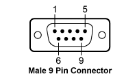
| CAB400 (9 Pin Male) Cable | |
|---|---|
| Pin # | Description |
| 1 | Interlock and Status LASER ON/OFF |
| 2 | Photodiodea |
| 3 | Laser Diode Ground |
| 4 | Photodiodeb |
| 5 | Ground for Pin 1 |
| 6 | Voltage Measurement Laser Diode Cathodec |
| 7 | Laser Diode Cathode (with Polarity Anode Grounded - AG) |
| 8 | Laser Diode Anode (with Polarity Cathode Grounded - CG) |
| 9 | Voltage Measurement Laser Diode Anodec |
| Table G3.1 Recalibration Service | |
|---|---|
| Calibration Service Item # | Compatible Drivers |
| CAL-LDC2 | LDC200CV LDC201CU LDC202C LDC205C LDC210C LDC220C LDC240C |
Thorlabs offers a recalibration service for our LDC200C Series Laser Diode Drivers. To ensure accurate measurements, we recommend recalibrating the devices every 24 months. Table G3.1 lists the drivers for which the CAL-LDC2 recalibration service is available.
Requesting a Calibration
Thorlabs provides two options for requesting a calibration:
- Complete the Returns Material Authorization (RMA) form. When completing the RMA form, please enter your name, contact information, the Part #, and the Serial # of the item being returned for calibration; in the Reason for Return field, select "I would like an item to be calibrated." All other fields are optional. Once the form has been submitted, a member of our RMA team will reach out to provide an RMA Number, return instructions, and to verify billing and payment information.
- Enter the Part # and Serial # of the item that requires recalibration below and then Add to Cart. A member of our RMA team will reach out to coordinate return of the item for calibration. Should you have other items in your cart, note that the calibration request will be split off from your order for RMA processing.
Please Note: To ensure your item being returned for calibration is routed appropriately once it arrives at our facility, please do not ship it prior to being provided an RMA Number and return instructions by a member of our team.