

Compact CMOS Spectrometers
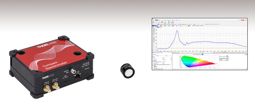
- Three Models for Wavelengths Ranging from 200 to 1000 nm
- Compact Size: 112.0 mm x 93.8 mm x 41.5 mm
- External Trigger Input and Output
- Cosine Correctors Available Separately for Free-Space
Measurements
CCT10
200 - 1000 nm Spectrometer,
<2.0 nm Resolution
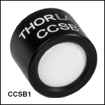
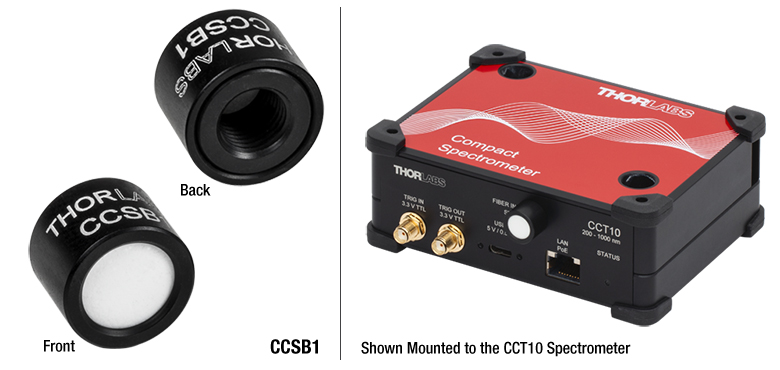
CCSB1
Cosine Corrector for
Thorlabs' CMOS Spectrometers
Versatile Display and Analysis Options
Flexible User Interface
OVERVIEW
| Item # | CCT10 | CCT11 | CCT12 |
|---|---|---|---|
| Wavelength Range | 200 - 1000 nm | 350 - 700 nm | 500 - 1000 nm |
| Resolution | <2.0 nm | <0.5 nm | <0.6 nm |
| Signal to Noise Ratio | 330:1 | 300:1 | |
| Detector Type | CMOS | ||
| Integration Time | 10 μs - 30 s | ||
Features
- Models for Broadband, Visible, and NIR Spectral Ranges
- Internal Shutter (<10 ms Switching Time) Allows Fast Background Subtraction
- Amplitude Corrected and Wavelength Calibrated
- Input and Output Triggers with Low Jitter (1 μs) for External Synchronization (TTL)
- PC Connection via USB or Ethernet Interface
- Rugged Crossed Czerney-Turner Spectrometer Design
- 2048 or 4096 Pixel CMOS Line Array
- Includes Multimode Fiber Patch Cable
- Compact Size: 112.0 mm x 93.8 mm x 41.5 mm (4.41" x 3.69" x 1.63")
- Horizontal or Vertical Mounting Options:
- Horizontal Mounting Using Two Through Holes for 1/4"-20 (M6) Screws
- Two Slots for Vertical Mounting with CL4 Clamps
- Cosine Correctors Available Separately Allow Free-Space Input
- Round-to-Linear Fiber Bundles Optimized for Spectrometer Use Available Separately Below
Thorlabs' compact Crossed Czerny-Turner Spectrometers are available in three models that accept input from an SMA-terminated patch cable. The CCT10 spectrometer offers a wide 200 - 1000 nm spectral range with better than 2 nm resolution. The CCT11 and CCT12 spectrometers have sub-nanometer resolution; one provides detection in the 350 - 700 nm range and the other in the 500 - 1000 nm range, respectively. With dimensions of 112.0 mm x 93.8 mm x 41.5 mm that measure roughly the size of a portable hard drive, the performance of these spectrometers is ideal for educational, research, and OEM applications and for fiber-based systems. Each unit comes wavelength calibrated and amplitude corrected and is shipped with a calibration report and test data.
Although small, these units share features with larger, more expensive spectrometers, such as the ability to be synchronized with other devices via TTL trigger input or output and to automatically compensate for the background from the dark current. Both the input and output triggers have low jitter (1 µs), and can be used for applications which require precise timing, such as Laser-Induced Breakdown Spectroscopy. These fiber-coupled spectrometers also integrate naturally into any fiber-based optical system, such as a photonic integrated circuit (PIC) testing station; see the PIC Testing Demo tab for details.
Each spectrometer ships with a 2 m high-speed USB 2.0 type-A to type-C cable and a 2 m long fiber optic patch cable with SMA905 connectors; see the Specs tab for the fiber type included with each spectrometer. These spectrometers are factory calibrated and amplitude corrected with the included patch cable prior to shipment.
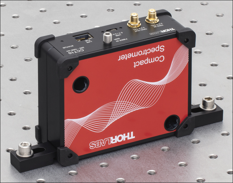
Mounting Options
For ease and stability of mounting, our compact CMOS spectrometers are each equipped with two holes through the housing for horizontally mounting to optical tables with 1/4"-20 (M6 x 1.0) screws. Additionally, the spectrometers have two slots for use with CL4 clamps for vertical mounting, as shown in the image to the left.
Software Package for CCT Series Spectrometers
The ThorSpectra software package provides full control of the CCT series spectrometers by a PC with a USB type-B input port, using the included cable, or an Ethernet input port. If a USB type-A input port to the PC that will be used to control the spectrometer is not available, any shielded USB type-C cable can be used to connect the spectrometer to a USB type-C input port on the PC.
The software package features a graphical user interface (GUI) and a set of drivers for .NET, Python, and NI LabVIEWa. The GUI can display the spectra, background, and peaks in a single window if desired. Additionally, diverse algorithms can be applied for smoothing, averaging, or calculating absorption and transmission. The measurement results can be compared with other stored profiles. If a calibrated spectral source is available, a user wavelength calibration can be performed; the user can then select either the user or factory calibration.
Please see the User Interface tab for more details. The drivers included in the software package allow for complete functional control of the spectrometers featured here, allowing the user to design his or her own interface software or to integrate the unit with a test and measurement setup for automated testing. The link to download the software can be found on the Software tab. This software package can also control Thorlabs' optical spectrum analyzers, although a separate software download is required for each instrument series in order to install the necessary device drivers.
Cosine Correctors
Thorlabs cosine correctors (available below) are designed to mate with either an SMA connectorized fiber or the input port of our CCT series spectrometer. They feature diffusers at the input apertures and allow the spectrometers to be used for free-space measurements.
Fiber Bundles
In addition to the SMA-to-SMA patch cable included with each spectrometer (detailed above), Thorlabs offers linear-to-round fiber bundles, which are sold below. These bundles are optimized for use with spectrometers and have a linear fiber array on the spectrometer side of the cable, which matches the geometry of the spectrometer slit. This provides higher signal levels in the spectrometer. See the Bundles vs Cables tab for details.
Thorlabs also offers a large selection of alternative fiber optic patch cables and bundles that may be purchased separately. For example, the M16L01 SMA-to-FC/PC-connectorized cable contains the same fiber as the M14L02 patch cable included with our CCT12 spectrometer. Our reflection probe fiber bundles are a single-cable solution that connects to the spectrometer, light source, and sample for reflection spectroscopy applications (see the Application tab for details). We also offer custom patch cables, which can be ordered here.
For accurate measurements, Thorlabs recommends updating the amplitude correction when using a different patch cable than the one included with the spectrometer through our recalibration service.
Recalibration Service for CCT Series Spectrometers
Thorlabs recommends recalibrating these spectrometers every 12 months and offers a factory recalibration service that includes wavelength calibration and amplitude correction. Although a user wavelength calibration can be performed in the software, amplitude correction requires a factory recalibration. If a replacement or alternative patch cable is used with the spectrometer, Thorlabs recommends factory recalibration using the new cable to update the amplitude correction. To order this service, scroll to the bottom of the page and select Item # CAL-CCT.
SPECS
All technical data are valid at 23 ± 5 °C, at 45 ± 15% relative humidity (non-condensing), and when the spectrometer is used in combination with the included fiber patch cables.
| Item # | CCT10 | CCT11 | CCT12 |
|---|---|---|---|
| Optical Specs | |||
| Wavelength Range | 200 - 1000 nm | 350 - 700 nm | 500 - 1000 nm |
| Resolution | <2.0 nm | <0.5 nm | <0.6 nm |
| Slit (W x H) | 20 µm x 1 mm | ||
| Number of Pixels on Detector | 2048 | 4096 | |
| Detector Technology | CMOS | ||
| Dark Noise (RMS) | 12 Counts | 14 Counts | |
| Scan Rate (GUI Limited) | 35 Hz | ||
| Stray Light | 0.2 % | 0.3% | |
| Internal Shutter Switching Time | <10 ms | ||
| Fiber Connector | SMA 905 | ||
| Sensor Specs | |||
| Integration Time | 0.01 - 30 000 ms (10 µs - 30 s) | ||
| Internal Average | 10 000 frames | ||
| Signal to Noise Ratio | 330:1 | 300:1 | |
| Dynamic Range | 5100 | 4500 | |
| Trigger Specs | |||
| Trigger Input and Output Connectors | Female SMA Connectors | ||
| Trigger Level | 3.3 V TTL | ||
| Trigger Jitter | 1 µs | ||
| General Specs | |||
| Interface | USB 2.0 or Higher, Ethernet IPv4 | ||
| Operating Temperature Rangea | 0 °C to 40 °C | ||
| Storage Temperature Range | 0 °C to 40 °C | ||
| Dimensions (L x W x H) | 112.0 mm x 93.8 mm x 41.5 mm (4.41" x 3.69" x 1.63") | ||
| Weight | 0.5 kg (1.1 lbs) | ||
| Included Patch Cable | |||
| Patch Cable Item #b | M111L02 | - | M14L02c |
| Fiber Item # | FG105ACA | FG050UGA | FG050LGA |
| Core Diameter | 105 +1/-3 µm | 50 ± 1 µm | |
| Cladding Diameter | 125 +1/-2 µm | ||
| Coating Diameter | 250 ± 10 µm | ||
| NA | 0.22 ± 0.02 | ||
| Wavelength Range | 180 to 1200 nm | 250 to 1200 nm | 400 to 2400 nm |
| Connectors | SMA905 | ||
| Patch Cable Length | 2 m | ||
USER INTERFACE
Graphical User Interface

Click to Enlarge
CCT Series Spectrometer GUI Peak Track Analysis Tool
The Peak Track analysis tool tracks the position, amplitude, and width of peaks in the spectrum over time.
Features
- Operates up to 10 Devices Simultaneously
- Auto-Detection of Compatible Devices
- Normalized Y Axis
- User Selectable Colors and Shapes for Each Spectral Trace
- Persistence Option Allows Visualization of Spectral Changes Over Time
- Saving and Retrieval of Scans (JCAMP-DX or CSV)
- Copy Data to Clipboard Function
- Printable Windows
- Tabbed or Floating Windows
- User Wavelength Calibration
- Polynomial or Gaussian Data Fitting
- Available Filters: Peak Finder, Smoothing, Averaging, Flip/Revert Picture
- Algorithms: Gaussian Transformation, Absorbance, Transmittance and Relative Difference Measurement
Adjustable Parameters
- Integration Time
- Trigger Modes: Internal, External, Continuous, Single Shot
- Averaging Method: Gliding or Block Average
- Smoothing Method: Block Smoothing
- Display Mode: nm or Pixel
The CCT Series Spectrometers feature an easy-to-use software package with a graphical user interface. The package is designed for laboratory and manufacturing applications. The data, background, and peaks can be shown in a single graph. With the help of smoothing and averaging algorithms the user is able to enhance specific features of the spectra. Furthermore, the software is able to handle several devices at one time, with the output from all of the devices presented in a single graph.
The screenshot to the upper right shows the Peak Track analysis mode, which allows the position, amplitude, and width of peaks in the spectrum to be tracked over time. As long as track peak mode is active, the track peak analysis area will be displayed below the graph. A table with information on each peak is to the lower right while the lower left of the screen contains a small toolbox used to set the criteria for identifying the peaks.
Additionally, Thorlabs provides drivers for .NET, Python, and NI LabVIEW for more specific demands. The software package supports LabVIEW versions 14 and up.
Data Processing
The software allows stored data to be loaded for comparison. This data can be used to calculate and show the absorbance, transmittance, or relative difference view.
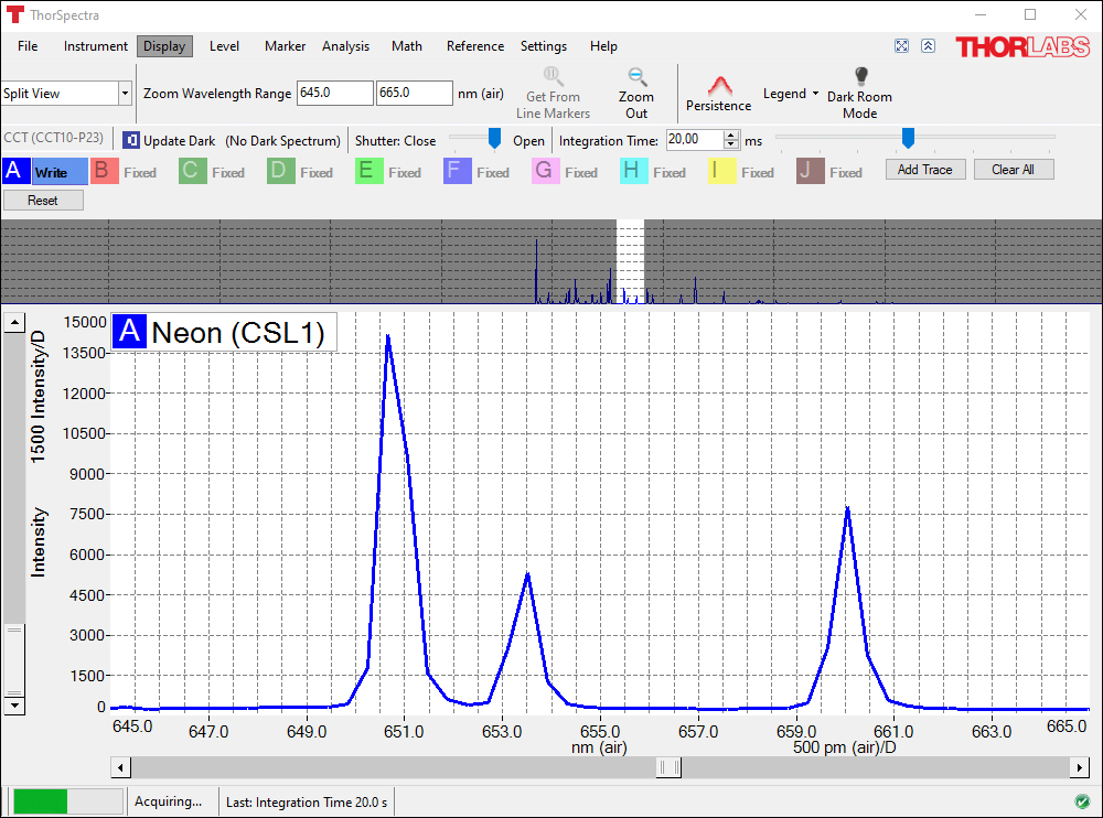
Click to Enlarge
CCT Series Spectrometer GUI Split View Screen
The Split View display option shows the full spectrum at the top of the screen, while a user-selectable portion of the spectrum is shown below.
Click to Enlarge
CCT Series Spectrometer GUI Color Analysis Tool
The Color Analysis tool calculates the chromaticity coordinates and the main wavelength in the spectrum using the CIE 1931, CIE 1960, or CIE 1976 color space.
SOFTWARE
Software
Version 3.35
This version includes a GUI for controlling the CCT spectrometers, as well as a "virtual device" mode ideal for evaluating the software prior to purchase.
![]()
Software for CCT Spectrometers
The software package for Thorlabs' Compact CCT Series Spectrometers includes a GUI and instrument drivers. For information on writing your own application, including information on additional drivers and tools, see chapter 4 of the CCT Series Spectrometers manual.
This software package can also control Thorlabs' optical spectrum analyzers, although a separate software download is required for each instrument series in order to install the necessary device drivers.
SHIPPING LIST
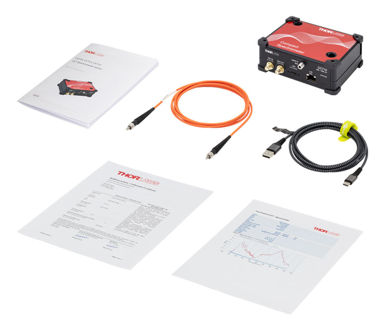
Click to Enlarge
The CCTxx Spectrometer is shipped with an appropriate patch cable, USB cable, and paper copies of the Amplitude Correction Test Report, Certificate of Calibration, and Quick Reference Guide.
The CCT10 Spectrometer contains the following components:
- Compact Spectrometer for 200 - 1000 nm
- M111L02 SMA MM Fiber Patch Cable, NA 0.22, 105 µm Core, 2 m*
- USB 2.0 Type-A to Type-C Cable, 2 m
- Test Report
- Certificate of Calibration
- Quick Reference Guide
The CCT11 Spectrometer contains the following components:
- Compact Spectrometer for 350 - 700 nm
- SMA MM Fiber Patch Cable (Contains FG050UGA Fiber), High OH, NA 0.22, 50 µm Core, 2 m*
- USB 2.0 Type-A to Type-C Cable, 2 m
- Test Report
- Certificate of Calibration
- Quick Reference Guide
The CCT12 Spectrometer contains the following components:
- Compact Spectrometer for 500 - 1000 nm
- M14L02 SMA MM Fiber Patch Cable, Low OH, NA 0.22, 50 µm Core, 2 m*
- USB 2.0 Type-A to Type-C Cable, 2 m
- Test Report
- Certificate of Calibration
- Quick Reference Guide
*Each spectrometer is calibrated with the included patch cable.
PIC TESTING DEMO
PIC Demo Testing Station
Thorlabs offers a variety of components that enable construction of a photonic integrated circuit (PIC) testing station, including imaging systems, fiber optics, precision piezos, and manual stages. This page presents a demo system that drives an on-chip laser and collects and analyzes the emitted light. The laser chip employed in this example PIC testing setup is a fully integrated, heterogeneous GaAs-on-SiN platform with an array of tunable lasers, with each source capable of coarsely covering the range from 765 to 795 nm. This PIC chip was supplied by Nexus Photonics. The scheme of this PIC testing demo can be generalized and customized to meet the needs of testing various PIC chips and is not restricted to the specific circuit used here. Click on the highlighted areas in Figure 787B or the links in Table 787A to find descriptions of the subsystems that comprise the demo testing station. Tables 787C and 787D provide a comprehensive list of all parts used in the demo.
| Table 787A PIC Demo Subsystems | |||||
|---|---|---|---|---|---|
| Imaging | Light Collection | PIC Control and Readout | PIC Chip Stage | Probe Card Positioning | General Setup |
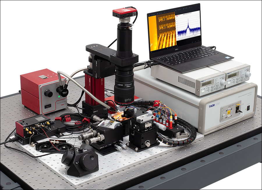
Figure 787B PIC Testing Demo Setup
| Table 787C PIC Demo Parts List | ||
|---|---|---|
| Item # | Qty. | Description |
| N/A | 1 | PIC Chip (Supplied by Nexus Photonics) |
| Imaging | ||
| SFM2a | 1 | Cerna® Mini Microscope |
| MCM301 | 1 | Three-Channel Stepper Motor Controller for Cerna Components |
| MCMK3 | 1 | 3-Knob USB HID Joystick |
| PLSXY | 1 | 2D Motorized Translation Stage for Rigid Stands |
| PLSZ | 1 | Motorized Module with 1" Travel, 95 mm Dovetail |
| LP126CU(/M) | 1 | Kiralux® Low-Profile 12.3 MP Color CMOS Camera |
| SM2CEFM | 1 | Adapter with External SM2 Threads and Female EF-Mounting Ring |
| CXY1A | 1 | XY Translating Lens Mount for Ø1" Optics |
| N/A | 1 | Canon Macro Lens |
| OSL2 | 1 | High-Intensity Fiber-Coupled Illuminator with Fiber Bundle |
| OSL2YFB | 1 | Gooseneck Y-Bundle for OSL2 and OSL2IR Fiber Light Sources |
| Light Collection | ||
| LFM1F-1 | 1 | FC/PC to Lensed Tip Fiber Patch Cable, Ø50 µm, 0.20 NA |
| TM50R2F1B | 1 | 1x2 Multimode Fiber Optic Coupler, Low OH, Ø50 µm Core, 0.22 NA, 90:10 Split, FC/PC |
| ADAFC3 | 2 | FC/APC to FC/APC Mating Sleeve |
| MAX311D(/M) | 1 | 3-Axis NanoMax™ Stage, Differential Drives, Closed-Loop Piezos |
| PY004(/M) | 1 | High-Load Pitch and Yaw Platform |
| KNA-VIS | 1 | K-Cube® NanoTrak® Active Auto-Alignment Controller, 320 - 1000 nm |
| KPC101 | 1 | K-Cube Piezo Controller and Strain Gauge Reader (Not Shown) |
| KCH301 | 1 | USB Controller Hub and Power Supply for Three K-Cubes or T-Cubes |
| Table 787D PIC Demo Parts List (Continued) | ||
|---|---|---|
| Item # | Qty. | Description |
| PIC Control and Readout | ||
| LDC202C | 2 | Benchtop LD Current Controller, ±200 mA HV |
| OSA202C | 1 | Fourier Transform Optical Spectrum Analyzer |
| PIC Chip Stage | ||
| MVS05(/M) | 1 | 1/2" Travel Vertical Translation Stage |
| N/A | 1 | Custom Machined Copper Mount for Chip Stage |
| Probe Card Positioning | ||
| XRV1(/M) | 1 | 14.0 mm Travel Vertical Translation Stage |
| LX20(/M) | 1 | Self-Contained XY 25 mm Translation Stage |
| N/A | 1 | Signatone Probe Card Holder |
| N/A | 1 | Custom Machined Probe Card Adapter |
| General Setup, Organization, and Cable Management | ||
| MB1824Ua | 1 | 18" x 24" Unanodized Aluminum Breadboard |
| CMS015 | 1 | Slit Harness Wrap, 5 m (16.5 ft) |
| BFCT | 1 | Passive Component Fiber Tray |
| CSV4 | 1 | Hook-and-Loop-Fastener Cable Straps with Lockdown Rivet (Qty. 5) |
| CS1 | 1 | Screw-On Cable Straps (Qty. 15) |
| B3648FXb | 1 | 36" x 48" Optical Breadboard |
| SDA90120 | 1 | ScienceDesk Frame for 36" x 48" (900 mm x 1200 mm) Tabletops |
Imaging

Click to Enlarge
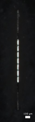
Figure 787E Image of PIC chip, probes, and collection fiber acquired by the imaging system. The lensed fiber used for light collection can be seen in the lower left of the image. The scale bar shows 1 mm.
A widefield imaging systema is necessary to facilitate alignment of the probe card and light collection (lensed fiber) systems relative to the the PIC chip. Thorlabs' SFM2 Cerna® Mini Microscope provides a simple means to construct an imaging systemb. An LP126CU Kiralux® Scientific Camera attached to the SFM2 Mini Microscope displays the image of the PIC chip, probe card, and collection fiber (shown in Figure 787E). Illumination from a light source like the OSL2 High-Intensity Fiber-Coupled Illuminator can be guided to the chip via the OSL2YFB gooseneck fiber bundle. The combination of an MCM301 Stepper Motor Controller and an MCMK3 USB Joystick with the PLSXY and PLSZ Motorized Translation Stages enables three-dimensional motorized control of the imaging system.
- In this context widefield means an imaging field comparable to the size of the PIC chip.
- An EF-Mount Adapter Ring such as the SM2CEFM can be used to connect the camera lens to the Cerna microscope.


Click to Enlarge
Figure 787F PIC Chip Close Up Showing Probe Card, Collection Fiber, Illumination, and Imaging Microscope
Light Collection
Figure 787F shows a close up of the light collection geometry. Light emitted from the chip is collected by an LFM1F-1 Lensed Multimode Fiber and coupled into an optical spectrum analyzer (as discussed in the previous section). If multiple facets of analysis are desired, the signal can be split using a multimode fiber optic coupler such as the TM50R2F1B. To achieve adequate signal-to-noise ratio, fine positional control of the collection fiber is necessary. Thorlabs offers many components enabling precision control of fiber optics. Thorlabs' NanoMax™ line provides precision fiber positioning, and a PY004 base allows pitch and yaw control. The NanoMax MAX311D contains piezos, which can be controlled for auto-alignment with a combination of the KNA-VIS and KPC101 K-Cube® Controllers. The KCH301 and KCH601 K-Cube mounts are available as a USB hubs for the K-Cubes.


Click to Enlarge
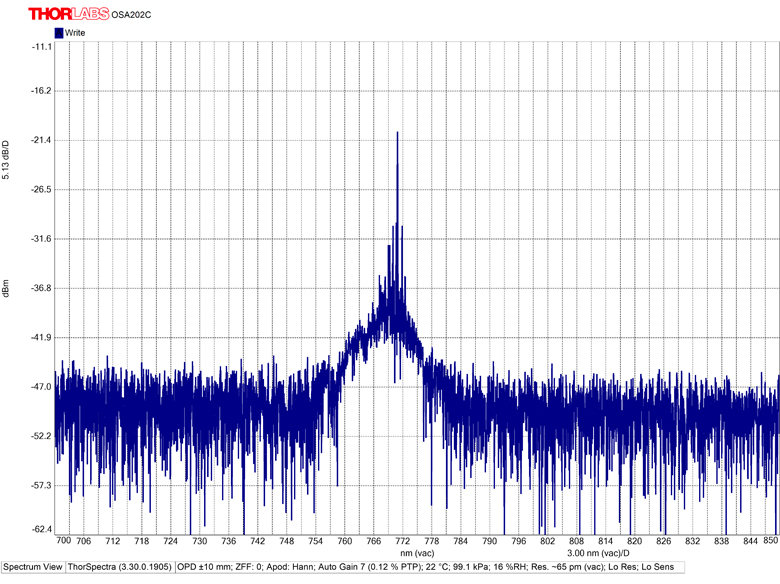
Figure 787G Screenshot of Spectrum Acquired with the OSA202C
PIC Control and Readout
In order to drive the laser circuit on the chip, current is supplied to the PIC chip via the probe card. Two LDC202C Laser Diode Drivers serve as the current sources here. Emitted light collected from the chip is directed into the fiber-coupled OSA202C Optical Spectrum Analyzer, which provides analysis and display of the signal. Figure 787G shows an example screenshot of the spectrum acquired by the OSA202C.
Depending on the particular PIC chip/testing application, various beam characterization and polarization measurement instruments can be used to construct a custom analysis setup to meet specific needs. Examples include the CCT10 Compact CMOS Spectrometer for spectroscopy, the PNA1 Intensity Noise Analyzer for high frequency-axis noise analysis, and the PAX1000IR1 Polarimeter for polarization measurements.
 |
 |
 |
 |
 |
| Laser Diode Drivers | Optical Spectrum Analyzers | Compact CMOS Spectrometers | Intensity Noise Analyzer | Polarimeters |
Positioning


PIC Chip Stage
Vertical (Z-axis) control of the PIC chip aids in focusing the widefield imaging system. A vertical drive stage such as the MVS05 Stage provides this additional degree of freedom. If more range is needed, the MVS1 Vertical Translation Stage allows up to 1" of travel.
Probe Card
The probe card serves to supply a multipoint electrical contact directly to the on-chip devices. To achieve optimal/flush contact with the chip multiple degrees of freedom are necessary. A vertical translation stage such as the XRV1 Stage provides vertical translation, and the LX20 Stage allows XY translation.
Thorlabs offers a wide selection of manual stages including linear translation, rotation, and multi-axis stages.
 |
 |
 |
 |
 |
| Optical Tables, Breadboards, and Supports | Solid Aluminum Breadboards | ScienceDesk Workstations | ScienceDesk Shelving | Cable Management |
General Setup, Organization, and Cable Management
Thorlabs offers a wide selection of general components and tools for construction, organization, and management of a PIC testing station. Optical tables, breadboards, and supports provide the foundation of any testing setup. ScienceDesk™ workstations can provide a convenient means to construct a vibration isolated table with a small footprint, and shelving affords convenient options for holding tools, equipment, and instruments. Cable management products for electric and fiber optic cables are also available.
Custom Capabilities
Both the lensed fiber holder and probe card holder were custom made for this specific PIC testing station demo application. Thorlabs offers a wide variety of custom solutions and manufacturing capabilities for various applications. Contact techsales@thorlabs.com for further information.
APPLICATION
Reflection Spectroscopy Application
Our reflection spectroscopy probes, CMOS spectrometers, lamp-based light sources, and fiber probe holders can be used together to take diffuse reflection, specular reflection, and color measurements.

Spectrometers
Thorlabs offers several CMOS-based spectrometers for use in the visible, NIR, or UV to NIR spectral ranges. The extended-range CCT10 spectrometer operates in the 200 - 1000 nm spectral range with <2.0 nm resolution. The CCT11 and CCT12 spectrometers operate in the 350 - 700 nm or 500 - 1000 nm spectral ranges with <0.5 nm or <0.6 nm resolution, respectively.
Light Sources
The SLS201L tungsten-halogen fiber-coupled light source delivers a 2796 K blackbody-type spectrum in the 360 - 2600 nm wavelength range and has active electronic stabilization for low spectral and intensity drift. Alternatively, the SLS203F Globar fiber-coupled light source provides a 1500 K temperature and 500 - 9000 nm emission range. We also offer fiber-coupled LEDs available with a selection of peak wavelengths or a broadband white-light emission spectra and our line of fiber-coupled laser sources offers a selection of options for intense single-wavelength illumination.
 Click to Enlarge
Diffuse Measurement Taken at 45° Using RPH Holder Block
Reflection Probe Fiber Bundles
Thorlabs offers reflection probes with either high-OH or low-OH multimode fiber for wavelengths from 250 - 1200 nm and 400 - 2400 nm, respectively. Probes are available with a sample end that terminates in either a Ø1/4" probe or an SMA905 connector. We also offer Ø1/4" and SMA-terminated probes with linear fiber bundle spectrometer ends that provide increased spectrometer coupling efficiency for samples with low reflectance. See the Bundles vs Cables tab for details.
If the coaxial illumination provided by a reflection probe bundle is not critical, separate fiber patch cables or bundles with SMA connectors can be used for illumination and signal collection. Our large-core round bundles maximize illumination intensity, while our single-fiber multimode SMA patch cables are useful for precise illumination, or for connection to a fiber-coupled laser. We also offer round-to-linear fiber bundles, which maximize signal strength at the spectrometer.
Reflection Probe Holders
Thorlabs offers the RPS and RPS-SMA fiber probe stands (RPS-SMA shown above and to the right), which allow for precise, stable positioning of the fiber optic probe at an angle of 90° or 45° relative to the sample. The probe holder arms (also sold separately) can also be integrated into other optomechanical setups using Ø1/2" posts. Alternatively, the RPH and RPH-SMA probe holder blocks sit directly on a sample, allowing the fiber tip to be positioned close to the surface and also blocking out room lights from the area under test.
BUNDLES VS CABLES
Linear Fiber Bundles vs. Single-Fiber Patch Cables
Entrance Slit Throughput Comparison
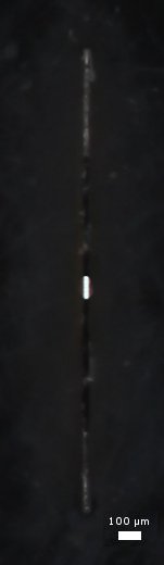
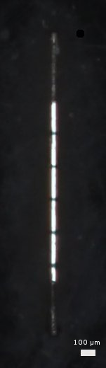
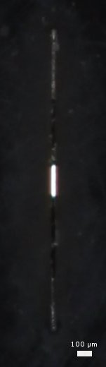
Our linear fiber bundles (sold below) can be used in place of the single-fiber patch cables included with these spectrometers to provide a significant increase in signal strength. The images below show how light exiting a linear fiber bundle more closely matches the geometry of the spectrometer's entrance slit than that from a standard patch cable. The accompanying graphs show comparison spectra of an SLS201L broadband light source measured with a CCT10 spectrometer when using a linear bundle versus a standard patch cable. As shown in the graphs below, the Ø105 µm core linear bundles provide a maximum power increase of ~50% versus a comparable single-fiber cable, while the Ø200 µm core linear bundles provide a maximum power increase of ~70%.
Note that, if a replacement or alternative patch cable or fiber bundle is used with the spectrometer, Thorlabs recommends factory recalibration using the new cable to update the amplitude correction.
Ø105 µm Core Cable Comparison
Click to Enlarge
Click to Enlarge
Left: Light exiting the end face of a BFL105LS02 linear bundle placed behind the 20 µm x 1 mm entrance slit of the spectrometer.
Right: Light exiting the end face of an M111L02 fiber patch cable placed behind the 20 µm x 1 mm entrance slit of the spectrometer.
Click to Enlarge
Comparison of the spectra of an SLS201L broadband light source obtained with a CCT10 spectrometer when using the BFL105LS02 linear fiber bundle versus an M111L02 single-fiber patch cable. The linear bundle provides a ~50% increase in maximum signal strength.
Ø200 µm Core Cable Comparison
Click to Enlarge
Click to Enlarge
Left: Light exiting the end face of a BFL200LS02 linear bundle placed behind the 20 µm x 1 mm entrance slit of the spectrometer.
Right: Light exiting the end face of an FG200UCC fiber patch cable placed behind the 20 µm x 1 mm entrance slit of the spectrometer.
Click to Enlarge
Comparison of the spectra of an SLS201L broadband light source obtained with a CCT10 spectrometer when using the BFL200LS02 linear fiber bundle versus an FG200UCC single-fiber patch cable. The linear bundle provides a ~70% increase in maximum signal strength.
Compact CMOS Spectrometers


Click to Enlarge
The CCT10 Spectrometer is shown with a cosine corrector and included fiber patch cable. Cosine correctors are available separately below.
- Compact Crossed Czerny-Turner Spectrometer Design
- Choose from Three Wavelength Ranges:
- 200 - 1000 nm
- 350 - 700 nm
- 500 - 1000 nm
- Resolutions from <0.5 to <2 nm Available (See Table in Overview Tab for Details)
- PC Control with USB or Ethernet Connection
Thorlabs' Crossed Czerny-Turner Spectrometers are compact devices roughly the same size as a portable hard drive. Each spectrometer is wavelength calibrated and amplitude corrected and is shipped with a calibration report and amplitude correction test data. The test data is valid for both the spectrometer and the included patch cable. Thorlabs recommends recalibrating the spectrometer every 12 months, and also whenever a new patch cable will be used with the spectrometer, as the cable affects the amplitude correction. Thorlabs' offers a factory recalibration service; to order this service, scroll to the bottom of the page and select Item # CAL-CCT.
The input port accepts SMA905-connectorized fibers, and the CCSB1 cosine corrector available below can be used to adapt the spectrometers for free-space applications.
Part Number | Description | Price | Availability |
|---|---|---|---|
CCT10 | NEW! Compact Spectrometer, Broadband, 200 - 1000 nm, <2.0 nm Resolution | $3,531.00 | Lead Time |
CCT11 | NEW! Compact Spectrometer, Visible, 350 - 700 nm, <0.5 nm Resolution | $3,531.00 | Today |
CCT12 | NEW! Compact Spectrometer, NIR, 500 - 1000 nm, <0.6 nm Resolution | $3,531.00 | Today |
Cosine Correctors for CCT and Legacy CCS Series Spectrometers
- Small Diffuser Connects to SMA-Connectorized Fibers or Spectrometer Input Port
- Allows Thorlabs' CCT and Legacy CCS Series Spectrometers to be Used for Free-Space Measurements
- Reduces the Source Alignment Sensitivity of Measurements
Thorlabs' Cosine Correctors allow Thorlabs' CCT and legacy CCS Series Spectrometers to be used for free-space measurements. The correctors incorporate a diffuser in a tightly toleranced metal housing. The CCSA1 and CCSA2 correctors are designed to mate with SMA-connectorized fiber optic cables. The third corrector, Item # CCSB1, is designed to mate directly to the input port of the spectrometer. An image of each cosine corrector connected to a spectrometer can be viewed by clicking on the photos in the table below.
Click to Enlarge
The transmission of the diffuser material used in the cosine correctors. Each curve is normalized to the maximum measured transmission through that sample.
Click to Enlarge
The cosine correction plot for each diffuser can be viewed by clicking on the info icons in the table below.
The diffuser in a cosine corrector allows light to be collected from up to a 180° angle with the diffuser surface. This minimizes issues caused by sampling geometry inherent to other devices, such as bare fiber optics or collimating lenses. As such, these diffuser packages are ideal for use in spectral measurements or as irradiance probes.
A plot showing the transmission spectrum of spectralon is shown to the right. Each curve is normalized to the maximum measured transmission through that sample. Please note that the transmission is highly wavelength dependent when selecting a cosine corrector for your application.
The cosine correction plot and transmission spectrum for each cosine corrector can be viewed by clicking on the blue info buttons (![]() ) in the table below.
) in the table below.
| Item # | CCSA1 | CCSA2 | CCSB1 |
|---|---|---|---|
| (Click Photo for Details) |  |
 |
 |
| Cosine Correction and Transmission (Click for Details) |
|||
| Diffuser Thickness | 0.5 mm | 1 mm | |
| Transmission @ 660 nma | 0.2% | 0.1% | |
| Clear Aperture | Ø4 mm | Ø8.5 mm | |
| Housing at Input Aperture | Smooth Ø7.5 mm | Externally SM05 (0.535"-40) Threaded | Smooth Ø12.0 mm |
| Housing Material | Anodized Aluminum | ||
| Output Port | Accepts SMA Connectors | Connects Directly to CCS Series Spectrometer Input | |
| Suggested Mounting Adapters | AD8F | SM1A6T, AD12T | AD12NT, AD12F |
Part Number | Description | Price | Availability |
|---|---|---|---|
CCSA1 | Cosine Corrector for SMA-Connectorized Fiber | $175.39 | Today |
CCSA2 | Cosine Corrector for SMA-Connectorized Fiber, External SM05 Threads | $194.47 | Today |
CCSB1 | Cosine Corrector for CCT and Legacy CCS Series Spectrometers | $233.88 | Today |
Fiber Bundles with Linear Output
Click to Enlarge
Spectra of an SLS201L light source taken with a CCT10 spectrometer and both BFL200LS02 and M25L01 cables.
- Optimized for Use with our CCT and Legacy CCS Series Spectrometers
- Available with One Linear and One Round End or with Two Linear Ends
- Low- or High-OH, Ø105 µm or Ø200 µm Core Multimode Fiber
- Linear End Matches the Entrance Slit of a Spectrometer for Higher Signal Levels
These fiber bundles contain 7 fibers arranged in a line configuration (linear) at one end and either a line configuration or a circular configuration (round) at the other end. These fiber bundle cables are commonly used to increase the coupling efficiency into spectrometers that have an entrance slit, such as those sold above. The linear end matches the shape of the entrance slit better than a single fiber or round bundle configuration, and therefore increases the amount of light entering the spectrometer. These fiber bundles use SMA905 connectors for compatibility with most spectrometers. They are built with Ø105 µm or Ø200 µm core Thorlabs multimode fiber with either a high or a low hydroxyl ion (OH) content for 250 - 1200 nm or 400 - 2400 nm, respectively.
When plugging the linear end of the bundle cable into the spectrometer or another device, the fiber array must be aligned with the entrance slit. For ease of alignment, the fiber array's axis is indicated by a line on the connector sleeve. Precise alignment of the bundle and slit is not critical, but misalignment of more than ±5° can cause a reduction in signal strength. In order to maximize signal intensity, we recommend rotating the bundle while monitoring light levels in the spectrometer, and then tightening down the threaded portion of the SMA connector to lock the bundle in place. When using these bundles with our CCT and legacy CCS Series Spectrometers, the fiber array should be oriented vertically.
Each patch cable includes two rubber and two metal protective caps that shield the connector ends from dust and other hazards. Additional CAPM Rubber Fiber Caps and CAPSM Metal Threaded Fiber Caps for SMA-terminated ends are also offered separately.
Please visit our Round-to-Linear Bundles Page or Linear-to-Linear Bundles Page for full product details. We also offer 1-to-4 Fan-Out Cables with Linear Common End Configurations.
Part Number | Description | Price | Availability |
|---|---|---|---|
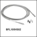
BFL105HS02 | Customer Inspired! Round-to-Linear Bundle, 7 x Ø105 µm Core Fibers, High-OH, SMA, 2 m Long | $318.44 | Today |
BFL200HS02 | Customer Inspired! Round-to-Linear Bundle, 7 x Ø200 µm Core Fibers, High-OH, SMA, 2 m Long | $358.27 | Today |
BFL200LS02 | Customer Inspired! Round-to-Linear Bundle, 7 x Ø200 µm Core Fibers, Low-OH, SMA, 2 m Long | $347.65 | Today |
BFL105LS02 | Customer Inspired! Round-to-Linear Bundle, 7 x Ø105 µm Core Fibers, Low-OH, SMA, 2 m Long | $318.44 | Today |
BFA105HS02 | Linear-to-Linear Bundle, 7 x Ø105 µm Core Fibers, High-OH, SMA, 2 m Long | $431.24 | Today |
BFA105LS02 | Linear-to-Linear Bundle, 7 x Ø105 µm Core Fibers, Low-OH, SMA, 2 m Long | $431.24 | Today |
BFA200HS02 | Linear-to-Linear Bundle, 7 x Ø200 µm Core Fibers, High-OH, SMA, 2 m Long | $469.72 | Today |
BFA200LS02 | Linear-to-Linear Bundle, 7 x Ø200 µm Core Fibers, Low-OH, SMA, 2 m Long | $469.72 | Today |
Recalibration Service for Compact CCT and Legacy CCS Series Spectrometers
| Calibration Service Item # | Compatible Spectrometers |
|---|---|
| CAL-CCT | CCT10, CCT11, CCT12 |
| CAL-CCS2 | CCS100(/M), CCS175(/M), CCS200(/M) |
Thorlabs offers a factory amplitude correction update and wavelength recalibration service for our Compact CCT and legacy CCS Series Spectrometers. To ensure accurate measurements, we recommend recalibrating the devices every 12 months. We also recommend recalibration whenever a new patch cable is going to be used with the spectrometer, as the cable used affects the amplitude correction. The table to the right lists the spectrometers for which the CAL-CCT and CAL-CCS2 recalibration service is available by purchasing the appropriate item below. When sending the part for recalibration, please include the patch cable that the spectrometer is being used with. For more information, please contact Tech Support.
Requesting a Calibration
Thorlabs provides two options for requesting a calibration:
- Complete the Returns Material Authorization (RMA) form. When completing the RMA form, please enter your name, contact information, the Part #, and the Serial # of the item being returned for calibration; in the Reason for Return field, select "I would like an item to be calibrated." All other fields are optional. Once the form has been submitted, a member of our RMA team will reach out to provide an RMA Number, return instructions, and to verify billing and payment information.
- Chose the appropriate Item # for the spectrometer using the table above, enter the Part # and Serial # of the item that requires recalibration below, and then click "Add to Cart". A member of our RMA team will reach out to coordinate return of the item for calibration. Should you have other items in your cart, note that the calibration request will be split off from your order for RMA processing.
Please Note: To ensure your item being returned for calibration is routed appropriately once it arrives at our facility, please do not ship it prior to being provided an RMA Number and return instructions by a member of our team.
Part Number | Description | Price | Availability |
|---|---|---|---|
CAL-CCT | NEW! Wavelength Calibration and Amplitude Correction Service for CCT Series Compact Spectrometers | $256.80 | Lead Time |
CAL-CCS2 | Wavelength Calibration and Amplitude Correction Service for Legacy CCS Series Compact Spectrometers | $252.02 | Lead Time |