 Products Home / Fiber Test & Measurement / PRO8 Modular Laser Diode Platform / Modular Test & Measurement Platforms
Modular Test & Measurement Platforms
- Modular Platform for Laser Diode Testing and Operation
- Locally Operated Using Built-In Front Panel
- Fast IEEE-488 and RS232 Interfaces for Remote Control
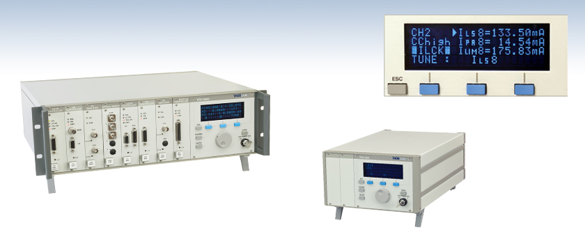
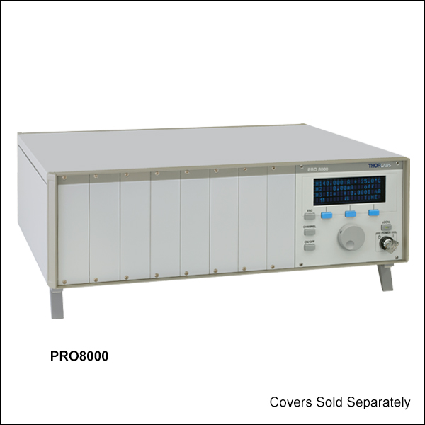
PRO8000
Shown with 8 Installed Modulesand Rack Mounting Adapter
Easy-to-Read Display
No PC Required for Operation
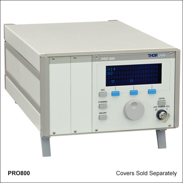
PRO800
2-Slot Benchtop Enclosure,
Shown with PRO8000-C Covers
(Sold Separately)

Please Wait
Features
- Universal, Modular Platform for Production and Quality Control
- Current and Temperature Controllers for Laser Diode Operation, Characterization, or Burn-In Applications
- Available Optical Modules Include WDM Laser Sources and Optical Switches
- Compact, 2-Slot Benchtop and Rack-Mountable 8-Slot Versions Available
- Remote Control via IEEE 488.2 and RS232
- Accessories Included with Chassis:
- Region-Specific Power Cord
- Manual
Thorlabs' PRO8 test and measurement platforms are designed to operate electrical and optical modules for telecom testing and other applications. They control a broad family of interchangeable modular devices (see Table 1.1) and can be operated independent of an external computer. Two different versions are available: 2-slot benchtop (PRO800), and 8-slot rack-mountable (PRO8000). The 8-slot chassis option is compatible with our 19" Rack Mounting System.
Modules
The PRO8 display menu allows easy configuration of any module in the chassis. Mnemonic symbols provide user-friendly access to all operational parameters. As long as modules are not moved to different slots during power down, all settings are retained in memory and automatically recalled upon powering on the mainframe. Individual modules are automatically identified and, when selected, can be configured and controlled using the front panel controls.
To meet individual experimental needs, PRO8 chassis are made to order and custom configured with individually selected modules. Prior to placing an order, please contact Tech Support so that we can assist with determining your custom configuration. Table 1.1 lists all available modules. Customers may also order the chassis and modules separately.
Different cables are required to connect the PRO8 modules to a Thorlabs Laser Diode Mount. The cables, which have a length of 1.5 m, must be ordered separately. Pin diagrams are shown near the bottom of this page.
| Item # | PRO800 | PRO8000 |
|---|---|---|
| Number of Slots | 2 | 8 |
| Mains Switch | Key-operated | |
| Remote Control | Via IEEE488.2 and RS232C | |
| Mains Supply | 100 V, 115 V, 230 V (±10%) Fixed (50 to 60 Hz) | |
| Maximum Power Consumption | 220 VA | 500 VA |
| Supply Mains Overvoltage | Category II | |
| Operating Temperature* | 0 - 40 °C | |
| Storage Temperature | -40 to +70 °C | |
| Relative Humidity | Max. 80% up to 31 °C, Decreasing to 50% at 40 °C | |
| Pollution Degree (Indoor Use Only) | 2 | |
| Operation Altitude | <2000 m | |
| Maximum Output Current per Slot | 4 A | 4 A |
| Maximum Output Current for all Slots | 8 A | 16 A |
| Warm-Up Time for Maximum Accuracy | 10 min | |
| Dimensions (W × H × D) | 232 mm × 147 mm × 396 mm (3 U) |
449 mm × 147 mm × 396 mm (3 U) |
| Maximum Weight | <9 kg | <17 kg |
| Display and Operating Elements | ||
| Display | 4 × 20 Characters Alphanumeric Vacuum-Fluorescence-Display | |
| User Interface | Interactive Menus | |
| Keypad | 7 Micro-Switch Keys | |
| Main Tuning Knob | Rotation Encoder | |
| Acoustic Messages | Internal Beeper: Short Tone As Confirmation, Long Tone As Warning | |
| Connectors on the Rear Panel | ||
| Ground | 4 mm Banana Jack | |
| Line | 3-Pin IEC 320 with Fuse | |
| Remote Control | IEEE488 (24-Pin) Jack or RS-232C (9-Pin) D-Sub Jack | |
| Auxiliary Jack | 9-Pin D-Sub (for Extensions) | |
| Trig In (5 V Max, TTL) | BNC | |
| Trig Out (5 V Max, TTL) | BNC | |
*Non-condensing
(All technical data are valid at 23 ± 5 °C and 45 ±15% relative humidity)
Software
Version 2.5.3
Click the button below to visit the software page.
Software for the PRO800/PRO8000 Series
The available software can be downloaded by clicking on the Software link, and is organized into the following categories:
- Drivers: Instrument drivers to directly operate the device via external software to extend or adapt the functionality to user specific requirements.
- Utility Module: Thorlabs Instrument Communicator 2 for instrument communication functionality.
| Posted Comments: | |
RWang27
(posted 2017-08-14 14:32:27.443) do u have any sample on how to connect the pro 800 on labview? just like the steps of how to build a connection between labview and pro 800 nreusch
(posted 2017-08-17 06:20:28.0) This is a response from Nicola at Thorlabs. Thank you very much for your inquiry. We do provide the LabVIEW drivers for our PRO800 modules, you can download them at https://www.thorlabs.com/software_pages/ViewSoftwarePage.cfm?Code=PRO8_Series. I will contact you directly to discuss the implementation in your LabVIEW program. user
(posted 2016-11-23 15:36:04.58) Dear Thorlabs,
I'm working with PRO800, LDC8040 and TED8020. Everything is working fine except PC connection. I use Ubuntu 16.04, python 3, pyserial and a USB-RS232-Converter. The connection speed seems a bit slow. I need 0.36-0.52 sec. to read an answer to something like b":LASER?\r\n" and 1.69-1.82 sec. to b":ILD:ACT?\r\n". I tried to use ":SYST:ANSW VALUE", but it didn't make any difference. I also changed baud rates. Is there a way to make it work faster?
With best regards
Mikhail swick
(posted 2016-11-25 05:25:11.0) This is a response from Sebastian at Thorlabs. Thank you for the inquiry.
I would recommend to work via GPIB interface, which should be faster. The speed of communication could be improved by activating the desired slot prior sending the command.
Unfortunately, you did not left any contact details. Please use techsupport@thorlabs.com for getting further technical support. tschalk
(posted 2012-12-13 06:13:00.0) This is a response from Thomas at Thorlabs. Thank you very much for your inquiry. If you are using the "Thorlabs Instrument Communicator" then you can find the instrument by typing "*?" into the suitable field and clicking SCAN CARDS. The PRO800 should appear in the table and you can double click it to make a connection. If you are using an older PRO8 system it will have a female 9-pin D-SUB connector on the rear panel. You should then use an 1:1 connection cable between PRO8 and PC. If you have a newer version with a 9-pin male connector you need a null modem cable shown in the manual on page 18, section 4: Communication with a PC. After the connection is made the window Serial Connection Configuration will appear. Please make sure that the Baud Rate matches with the Baud Rate of the device and select Flow Control RTS/CTS. If you now send the command "*IDN?" the display of the PRO800 should show "REMOTE" and you should receive a response like "Throlabs, Pro800, ...". If you type in for example ":SLOT 1" the green light beside SEL of Channel 1 should light up. If you don’t get any response then please make sure that you are using the correct type of interconnecting cable. carbonem
(posted 2012-12-12 07:05:39.85) Dear Sirs:
Recently we acquired a module controller based on a PRO800 chassis with a PDA8000-2 module for optical power measurement. By now it is connected to a high-speed photodetector DET36A/M.
We are trying to connect the controller to a PC by using an RS232 serial cable and to control the system in remote mode. However we are not able to communicate both devices properly. Therefore, to check the connection we are using your software “Thorlabs Instrument Communicator”.
The COM port flow control of our PC can be selected as “none”, “hardware” or “XON/XOFF”. However your software indicates that we must activate the “RTS /CTS” mode.
So far we have managed to send commands and to change the controller mode from local to remote or remote to local (to this end, we select the flow control mode in “none” or “disabled”). However but we do not receive a response back from the controller when we send request commands. Apparently, data travels from the PC to the controller, but not from the controller to the PC.
Please, could you give us any suggestion to get the connection in both directions?
Should we select a different flow control mode on the COM port?
Thank you very much in advance for your help.
Best regards, Laurie
(posted 2008-10-02 09:03:06.0) Response from Laurie at Thorlabs to edu6182: Thank you for your interest in our PRO800. The system comes with LabVIEW and CVI drivers on a CD ROM. Alternatively, you can download the files here: http://www.thorlabs.com/Support.cfm?Section=7&viewTab=1
Use the "Custom Installation" to add LabVIEW, LabWindows, and C++ drivers. edu6182
(posted 2008-09-30 08:08:23.0) Dear Sirs,
This is Enric Donés, an engineer from National Microelectronic Center in Barcelona (Spain). I need to use a PRO800 optical source for making some tests and I would like to know if there are available Labview drivers to control this device from a PC.
Thank you for you help.
Regards,
Enric Donés. |

 Zoom
Zoom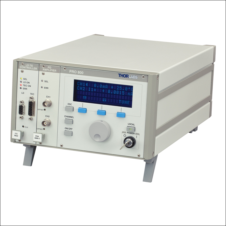 Click to Enlarge
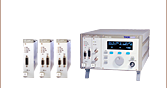
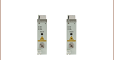
Figure G1.1 PRO800 Chassis with ITC8022 LD and TEC Controller and
PDA8000-2 Amplifier
| Key Specifications | ||||
|---|---|---|---|---|
| Number of Slots | 2 | |||
| Max Power Consumption | 220 VA | |||
| Max Output Current Per Slot | 4 A | |||
| Max Output Current for All Slots | 8 A | |||
- Compact, 2-Slot, Benchtop Chassis
- Ideal for Research Applications
- Compatible with Various Temperature and Current Controllers and Optical Switches
- Dimensions (W x H x D): 232 mm x 147 mm x 396 mm
(3 U Height)
The PRO800 Chassis is perfect for the lab environment and can accommodate up to two modules. This made-to-order chassis can be custom configured with up to two modules that best meet individual experimental needs prior to purchase (see Figure G1.1). The chassis can also be ordered empty, without any pre-installed modules. The empty slots of the PRO800 can be covered using PRO8000-C front cover plates (sold separately below).

 Zoom
Zoom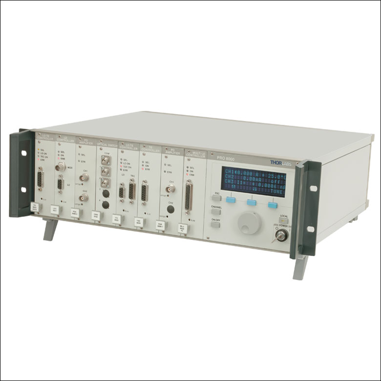 Click to Enlarge
| Key Specifications | ||||
|---|---|---|---|---|
| Number of Slots | 8 | |||
| Max Power Consumption | 500 VA | |||
| Max Output Current Per Slot | 4 A | |||
| Max Output Current for All Slots | 16 A | |||
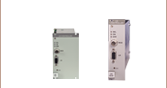
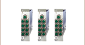
- 8 Slot Rack-Mountable Chassis
- Ideal for Large Testing and Manufacturing Environments
- Compatible with Various Temperature and Current Controllers and Optical Switches
- Dimensions (W x H x D): 449 mm x 147 mm x 400 mm
(3 U Height)
The PRO8000 Chassis can accept up to 8 modules and is ideally suited for the needs of large test setups. This made-to-order chassis can be custom configured with up to eight modules that best meet individual experimental needs prior to purchase (see Figure G2.1). The chassis can also be ordered empty, without any pre-installed modules. The empty slots of the PRO8000 can be covered using PRO8000-C front cover plates (sold separately below).
As shown inFigure G2.1, our PRO8000-R32 Rack-Mounting Handles (sold separately) can be attached to the chassis, allowing it to be integrated into our 19" Rack Mounting System.

 Zoom
Zoom Click to Enlarge
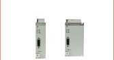
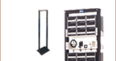
The PRO8000-R32 Rack Mounting Kit includes a pair of handles that allows the PRO8000 chassis to be mounted in a 19" rack system. To install the handles, the PRO8000 housing must be removed and reassembled using the existing housing screws to secure the handles to the unit. This process can be time consuming, but if the PRO8000-R32 handles are ordered with the PRO8000 chassis, the device will be delivered with the rack mountings fitted. The through holes can then be used to mount the chassis in a rack system. Please note: although the PRO800 is compatible with the PRO8000-R32 Mounting Kit, it is too narrow to fit in a 19" rack system.
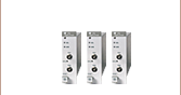
The PRO8000-C Front Cover Plate is used to protect empty slots in the PRO800 and PRO8000 chassis. To install, use the two Phillips head screws that previously attached the module to the chassis to secure the front plate to the chassis, just as if it were a module. Figure G3.1 shows the PRO800 chassis with one PRO8000-C front plate.

 Zoom
Zoom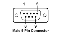
The CAB400 cable is used to connect our Laser Diode Current Controller modules to our Laser Diode Mounts.
| CAB400 (9 Pin Male) Cable | |
|---|---|
| Pin # | Description |
| 1 | Interlock and Status LASER ON/OFF |
| 2 | Photodiodea |
| 3 | Laser Diode Ground |
| 4 | Photodiodeb |
| 5 | Ground for Pin 1 |
| 6 | Voltage Measurement Laser Diode Cathodec |
| 7 | Laser Diode Cathode (with Polarity Anode Grounded - AG) |
| 8 | Laser Diode Anode (with Polarity Cathode Grounded - CG) |
| 9 | Voltage Measurement Laser Diode Anodec |

 Zoom
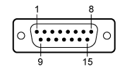
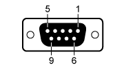
ZoomThe CAB420-15 cable is used to connect our TEC Temperature Controller modules to our Laser Diode Mounts. The pin descriptions shown in Tables G5.1 and G5.2 denote the typical pin assignments used by Thorlabs' family of laser diode temperature controllers and laser diode mounts. Table G5.3 gives the physical pin connections between the 15-pin and 9-pin sides of the CAB420-15 cable.
| Table G5.1 Male 15-Pin Connector | |
|---|---|
 |
|
| 1 | Status LED (+) (for TEC On/Off Indication)a |
| 2 | TEC Voltage Measurementb |
| 3 | Thermistor (-), Ground |
| 4 | Thermistor (+) |
| 5 | TEC (+) |
| 6 | TEC (+) |
| 7 | TEC (+) |
| 8 | LM 135/335 (-), Grounda |
| 9 | TEC Voltage Measurementb |
| 10 | Transducer AD 590/592 (-), LM 135/335 (+) |
| 11 | Transducer AD 590/592 (+), LM 135/335 (+) |
| 12 | No Connection |
| 13 | TEC (-), Status LED (-) |
| 14 | TEC (-), Status LED (-) |
| 15 | TEC (-), Status LED (-) |
| Table G5.2 Female 9-Pin Connector | |
|---|---|
 |
|
| 1 | Status LED (+) (for TEC On/Off Indication)a |
| 2 | Thermistor (+) |
| 3 | Thermistor (-), Ground |
| 4 | TEC (+) |
| 5 | TEC (-), Status LED (-) |
| 6 | No Connection |
| 7 | Transducer AD 590/592 (-), LM 135/335 (+) |
| 8 | LM 135/335 (-), Grounda |
| 9 | Transducer AD 590/592 (+), LM 135/335 (+) |
| Table G5.3 Pin Connections | |
|---|---|
| 15-Pin Side | 9-Pin Side |
| 1 | 1 |
| 2 | 4 |
| 3 | 3 |
| 4 | 2 |
| 5 | 4 |
| 6 | 4 |
| 7 | No Connection |
| 8 | 8 |
| 9 | 5 |
| 10 | 7 |
| 11 | 9 |
| 12 | No Connection |
| 13 | 5 |
| 14 | 5 |
| 15 | No Connection |

 Zoom
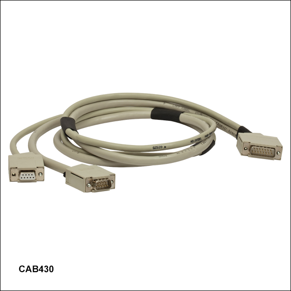
ZoomThe CAB430 cable is used to connect our Combination Laser Diode Current and TEC Temperature Controller modules to our Laser Diode Mounts.
 |
|
|
Pin Connections
|
 |
|
|
Pin Connections
|
 |
|
|
Pin Connections
|