Quartz-Wedge Achromatic Depolarizers
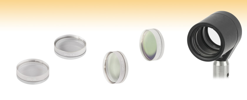
- Randomize the Polarization of a Linearly Polarized Input Beam
- Designed for Laser Beams >Ø6 mm
- Effective with Monochromatic and Broadband Light
- Available with AR Coatings
DPU-25
DPU-25-A
DPU-25-B
DPU-25-C
DPU-25-A Depolarizer
Mounted in an SM1 Lens Tube

Please Wait
| General Specifications | |
|---|---|
| Substrate | Quartz Crystal |
| Coatings | Uncoated (190 - 2500 nm) -A Coating (350 - 700 nm) -B Coating (650 - 1050 nm) -C Coating (1050 - 1700 nm) |
| Outer Diameter | 1" (25.4 mm) |
| Thickness | 7.35 mm (0.289") |
| Clear Aperture | >Ø21.59 mm |
| Surface Flatness | λ/10 @ 633 nm |
| Surface Quality | 10-5 Scratch-Dig |
| Item # Suffix | Damage Thresholds |
| -A | 7.5 J/cm² at 532 nm, 10 ns, 10 Hz, Ø0.504 mm |
| -B | 7.5 J/cm² at 810 nm, 10 ns, 10 Hz, Ø0.144 mm |
| -C | 7.5 J/cm² at 1542 nm, 10 ns, 10 Hz, Ø0.123 mm |
| Click on the red Document icon next to the item numbers below to access the Zemax file download. Our entire Zemax Catalog is also available. |
Click to Enlarge
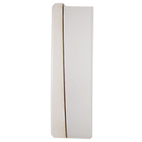
Figure 1.1 Edge-on View of the Quartz-Wedge Depolarizer
Features
- Optic Axis Alignment Not Required
- Ideal for Broadband Light Sources and Large Diameter (>6 mm) Monochromatic Beams
- Air-Gap Design Allows for use with High-Power Beams
- Available Uncoated (190 - 2500 nm) or with One of Three AR Coatings
- 350 - 700 nm (-A Coating)
- 650 - 1050 nm (-B Coating)
- 1050 - 1700 nm (-C Coating)
Thorlabs' Quartz-Wedge Achromatic Depolarizers convert a polarized beam of light into a pseudo-random polarized beam of light. The term pseudo-random is used since the transmitted beam does not become unpolarized; instead, the polarization of the beam is randomized. Linearly polarized light from a monochromatic source that is transmitted through a quartz-wedge depolarizer will have a polarization that varies spatially. Linearly polarized light from a broadband source that is transmitted through a quartz-wedge depolarizer will have a polarization that varies spatially as well as with wavelength. While the DPU-25 is designed for use with linearly polarized light (as shown in the Tutorial tab), it will also produce pseudo-random polarization if the input is elliptically or circularly polarized. Quartz-wedge depolarizers will work with light incident on either side of the optic.
Design
These achromatic depolarizers consist of two crystal quartz wedges, one of which is twice as thick as the other, that are separated by a thin metal ring. The assembly is held together by epoxy that has been applied only to the outside edge (i.e., the clear aperture is free from epoxy), which results in an optic with a high damage threshold. These depolarizers are available uncoated for use in the 190 - 2500 nm range or with one of three antireflection coatings deposited on all four surfaces (i.e., both sides of the two crystal quartz wedges). Choose from AR coatings for the 350 - 700 nm (-A coating), 650 - 1050 nm (-B coating), or 1050 - 1700 nm (-C coating) range.
The optic axis of each wedge is perpendicular to the flat for that wedge. The orientation angle between the optic axes of the two quartz crystal wedges is 45°. The unique design of the quartz-wedge depolarizers eliminates the need to orient the optic axes of the depolarizer at any specific angle, which is especially useful if the depolarizer is used in an application where the initial polarization of the light is unknown or varies with time.
The thickness of these optics prevents them from being mounted in our LMR1 optic mount. However, they can be mounted inside an SM1-threaded (1.035"-40) lens tube for integration into a lens tube system or post mounting via an LMR1 mount, as shown in the image at the top of the page.
Free-Space Applications
Although the quartz-wedge depolarizers can convert a polarized monochromatic or broadband source into a pseudo-random polarization, depolarization of narrowband (monochromatic) light sources can only be achieved if the incident beam is greater than 6 mm in diameter. This minimum beam diameter is needed for monochromatic sources because randomization of the output beam's polarization is achieved by producing a spatial variation in the beam's polarization (see the Tutorial tab). Thorlabs also offers liquid crystal polymer depolarizers that use a patterned retarder to effectively depolarize beams as small as Ø0.5 mm (see the Quartz vs. LCP tab for details).
Depolarization of a broadband source does not have the same beam diameter restrictions as found with the narrowband or monochromatic source. This is because the polarization of the output beam will be randomized as a result of the wavelength-dependent retardation of the light transmitted through the quartz crystal wedges, in addition to the spatial variation in the polarization of the output beam.
The pseudo-random polarization generated by these depolarizers may be more suitable than linearly polarized light for polarization-sensitive devices and experiments, such as Raman Amplification and reduction of polarization-dependent losses. Because of their effectiveness over a wide spectral range, with both narrowband and broadband sources, the quartz-wedge depolarizers have been used with favorable results in applications involving polarization-sensitive spectrometers and LCD test systems. In addition, the depolarizer's design eliminates the need to align the optic with respect to the orientation of the linear polarization axis of the incident beam, making them highly adaptable to varying input polarizations.
Fiber Applications
Thorlabs' quartz-wedge achromatic depolarizers are not recommended for applications where the depolarized beam is going to be coupled into a single mode optical fiber. Consider the output beam as two superimposed beams. Since the optic axes of the two wedges are not aligned, there will be a non-zero divergence/offset of the propagation vectors of the two output beams due to the birefringence of the quartz crystal. If the diverging/offset beams are then focused onto the tip of a fiber, each beam will be imaged at a slightly different position. As a result, optimizing the coupling of light into the fiber can result in the preferential coupling of one beam over the other and the polarization of each individual beam is not completely randomized.
Liquid Crystal Polymer (LCP) Depolarizers
These quartz-wedge depolarizers and our Liquid Crystal Polymer Depolarizers each offer distinct advantages depending on your application. The depolarizers featured here have a much better surface quality and a high damage threshold due to their use of a quartz substrate and air-gap design, which makes them suitable for high-power applications. The LCP depolarizers use a patterned retarder design that can effectively depolarize monochromatic beams down to Ø0.5 mm, while the quartz depolarizers typically require input beam diameters of at least 6 mm. The patterned retarder design used in the LCP depolarizers is also less sensitive to the angle of incidence. See the Quartz vs. LCP tab for a more detailed performance comparison.
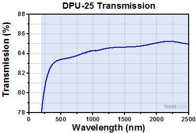
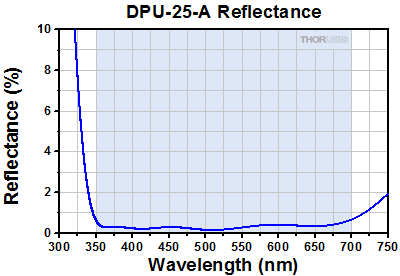
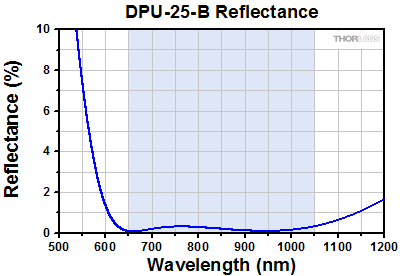
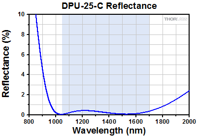
The DPU-25 is also available from stock with three different AR coatings. As Figures 2.1 through 2.4 show, the AR coating significantly reduces surface reflections, and since these depolarizers are made from two quartz crystal wedges, the AR coating minimizes the reflections at four surfaces. For example, the loss due to surface reflections at 1400 nm for the uncoated DPU-25 is approximately 15%. However, the AR coating on the DPU-25-C reduces the loss due to reflections to approximately 2%.
Click to Enlarge
Click for Raw Data
Figure 2.1 Measured transmission as a function of wavelength through an uncoated DPU-25 depolarizer.
Click to Enlarge
Click for Raw Data
Figure 2.2 Measured percent reflectance as a function of wavelength for the AR-coated surfaces of the DPU-25-A depolarizer.
Click to Enlarge
Click for Raw Data
Figure 2.3 Measured percent reflectance as a function of wavelength for the AR-coated surfaces of the DPU-25-B depolarizer.
Click to Enlarge
Click for Raw Data
Figure 2.4 Measured percent reflectance as a function of wavelength for the AR-coated surfaces of the DPU-25-C depolarizer.
| Table 3.1 Depolarizer Comparison | ||
|---|---|---|
| Depolarizer Type | LCP Patterned Retarder | Quartz-Wedge Design |
| Effective Beam Size | Down to Ø0.5 mm | Down to Ø6 mm |
| Surface Quality | 60-40 Scratch-Dig | 10-5 Scratch Dig |
| Thickness | 3.2 mm (0.13") | 7.35 mm (0.289") |
| Available Wavelengths | 350 - 700 nm (AR Coated) 650 - 1050 nm (AR Coated) 1050 - 1700 nm (AR Coated) |
190 - 2500 nm (Uncoated) 350 - 700 nm (AR Coated) 650 - 1050 nm (AR Coated) 1050 - 1700 nm (AR Coated) |
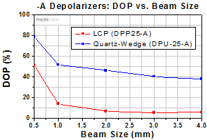
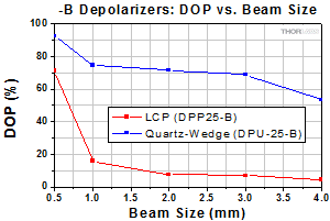
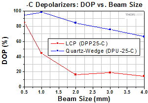
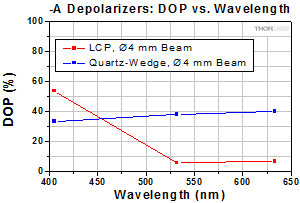
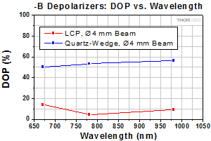
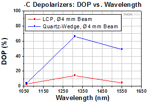
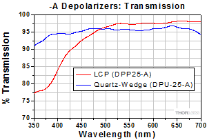
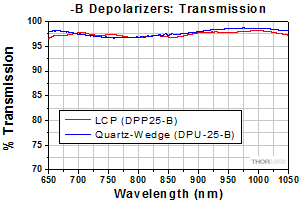
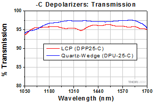
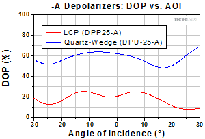
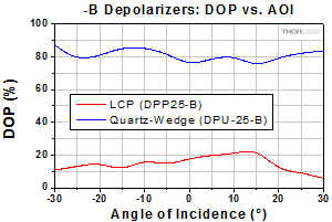
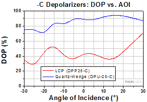
Figures 3.2 through 3.7 and 3.11 through 3.13 compare the degree of polarization (DOP) that can be achieved using the liquid crystal polymer (LCP) patterned depolarizers and our quartz-wedge depolarizers. Compared to the quartz wedge depolarizers, the LCP patterned depolarizers show greater performance stability with changing angle of incidence and can effectively depolarize smaller beam sizes, which is especially useful for laser applications. In contrast, the quartz-wedge depolarizers have a higher surface quality and damage threshold. They also provide better performance for depolarizing elliptically and circularly polarized light.
Degree of Polarization vs. Beam Size
Click to Enlarge
Figure 3.2 The DPP25-A is an LCP depolarizer and the
Click to Enlarge
Figure 3.3 The DPP25-B is an LCP depolarizer and the
Click to Enlarge
Figure 3.4 The DPP25-C is an LCP depolarizer and the
MCLS1-1310) laser diode module, 1 nm FWHM bandwidth.
Degree of Polarization vs. Wavelength
Click to Enlarge
Figure 3.5 The DPP25-A is an LCP depolarizer and the
Click to Enlarge
Figure 3.6 The DPP25-B is an LCP depolarizer and the
Click to Enlarge
Figure 3.7 The DPP25-C is an LCP depolarizer and the
*Replaced by the HRS015B stabilized HeNe Laser.
Depolarizer Transmission
Click to Enlarge
Figure 3.8 The DPP25-A is an LCP depolarizer and the
Click to Enlarge
Figure 3.9 The DPP25-B is an LCP depolarizer and the
Click to Enlarge
Figure 3.10 The DPP25-C is an LCP depolarizer and the
Degree of Polarization vs. Angle of Incidence
Click to Enlarge
Figure 3.11 The DPP25-A is an LCP depolarizer and the
Click to Enlarge
Figure 3.12 The DPP25-B is an LCP depolarizer and the DPU-25-B is one of Thorlabs' quartz-wedge depolarizers. This test was performed using a 780 nm laser diode module (CPS192, 1 nm FWHM bandwidth) with a beam size of Ø1 mm.
Click to Enlarge
Figure 3.13 The DPP25-C is an LCP depolarizer and the DPU-25-C is one of Thorlabs' quartz-wedge depolarizers. This test was performed using a 1310 nm (previous-generation
MCLS1-1310) laser diode module, 1 nm FWHM bandwidth, with a beam size of Ø1 mm.
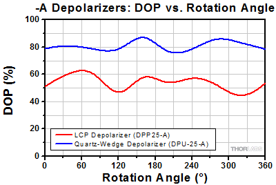
Degree of Polarization vs. Rotation Angle
Figure 3.14 is provided as an example of the variation in Degree of Polarization as the depolarizer is rotated. Actual performance will vary from depolarizer to depolarizer, depending on the alignment of the LCP pattern and the section of the depolarizer illuminated by the incident beam. Rotating a depolarizer around an axis perpendicular to its surface does cause some variation in performance, but overall, the LCP depolarizer still provides a lower degree of polarization for a Ø0.5 mm beam than the quartz-wedge design. Similar results can be expected from the -B and -C depolarizers.
Click to Enlarge
Figure 3.14 The plot above shows the performance of the depolarizer as it is rotated. The test was performed using a 532 nm CPS532 laser diode module (1 nm FWHM bandwidth) with a beam size of Ø0.5 mm. For the quartz-wedge depolarizer, 0° corresponds to the cut edge marking the fast axis of the thick wedge. For the LCP depolarizer, 0° corresponds to the line of parallel
| Table 4.1 Damage Threshold Specifications | |
|---|---|
| Item # Suffix | Damage Threshold |
| -A | 7.5 J/cm² at 532 nm, 10 ns, 10 Hz, Ø0.504 mm |
| -B | 7.5 J/cm² at 810 nm, 10 ns, 10 Hz, Ø0.144 mm |
| -C | 7.5 J/cm² at 1542 nm, 10 ns, 10 Hz, Ø0.123 mm |
Damage Threshold Data for Thorlabs' Achromatic Depolarizers
The specifications in Table 4.1 are measured data for Thorlabs' achromatic depolarizers.
Laser Induced Damage Threshold Tutorial
The following is a general overview of how laser induced damage thresholds are measured and how the values may be utilized in determining the appropriateness of an optic for a given application. When choosing optics, it is important to understand the Laser Induced Damage Threshold (LIDT) of the optics being used. The LIDT for an optic greatly depends on the type of laser you are using. Continuous wave (CW) lasers typically cause damage from thermal effects (absorption either in the coating or in the substrate). Pulsed lasers, on the other hand, often strip electrons from the lattice structure of an optic before causing thermal damage. Note that the guideline presented here assumes room temperature operation and optics in new condition (i.e., within scratch-dig spec, surface free of contamination, etc.). Because dust or other particles on the surface of an optic can cause damage at lower thresholds, we recommend keeping surfaces clean and free of debris. For more information on cleaning optics, please see our Optics Cleaning tutorial.
Testing Method
Thorlabs' LIDT testing is done in compliance with ISO/DIS 11254 and ISO 21254 specifications.
First, a low-power/energy beam is directed to the optic under test. The optic is exposed in 10 locations to this laser beam for 30 seconds (CW) or for a number of pulses (pulse repetition frequency specified). After exposure, the optic is examined by a microscope (~100X magnification) for any visible damage. The number of locations that are damaged at a particular power/energy level is recorded. Next, the power/energy is either increased or decreased and the optic is exposed at 10 new locations. This process is repeated until damage is observed. The damage threshold is then assigned to be the highest power/energy that the optic can withstand without causing damage. A histogram such as that shown in Figure 37B represents the testing of one BB1-E02 mirror.
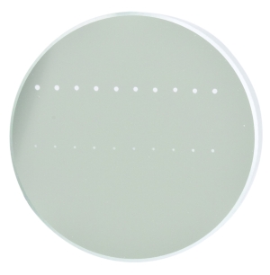
Figure 37A This photograph shows a protected aluminum-coated mirror after LIDT testing. In this particular test, it handled 0.43 J/cm2 (1064 nm, 10 ns pulse, 10 Hz, Ø1.000 mm) before damage.
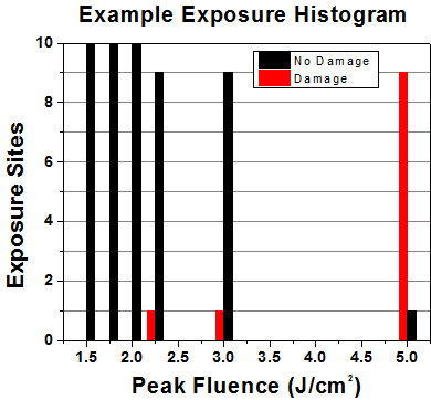
Figure 37B Example Exposure Histogram used to Determine the LIDT of
| Table 37C Example Test Data | |||
|---|---|---|---|
| Fluence | # of Tested Locations | Locations with Damage | Locations Without Damage |
| 1.50 J/cm2 | 10 | 0 | 10 |
| 1.75 J/cm2 | 10 | 0 | 10 |
| 2.00 J/cm2 | 10 | 0 | 10 |
| 2.25 J/cm2 | 10 | 1 | 9 |
| 3.00 J/cm2 | 10 | 1 | 9 |
| 5.00 J/cm2 | 10 | 9 | 1 |
According to the test, the damage threshold of the mirror was 2.00 J/cm2 (532 nm, 10 ns pulse, 10 Hz, Ø0.803 mm). Please keep in mind that these tests are performed on clean optics, as dirt and contamination can significantly lower the damage threshold of a component. While the test results are only representative of one coating run, Thorlabs specifies damage threshold values that account for coating variances.
Continuous Wave and Long-Pulse Lasers
When an optic is damaged by a continuous wave (CW) laser, it is usually due to the melting of the surface as a result of absorbing the laser's energy or damage to the optical coating (antireflection) [1]. Pulsed lasers with pulse lengths longer than 1 µs can be treated as CW lasers for LIDT discussions.
When pulse lengths are between 1 ns and 1 µs, laser-induced damage can occur either because of absorption or a dielectric breakdown (therefore, a user must check both CW and pulsed LIDT). Absorption is either due to an intrinsic property of the optic or due to surface irregularities; thus LIDT values are only valid for optics meeting or exceeding the surface quality specifications given by a manufacturer. While many optics can handle high power CW lasers, cemented (e.g., achromatic doublets) or highly absorptive (e.g., ND filters) optics tend to have lower CW damage thresholds. These lower thresholds are due to absorption or scattering in the cement or metal coating.

Figure 37D LIDT in linear power density vs. pulse length and spot size. For long pulses to CW, linear power density becomes a constant with spot size. This graph was obtained from [1].
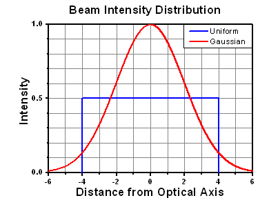
Figure 37E Intensity Distribution of Uniform and Gaussian Beam Profiles
Pulsed lasers with high pulse repetition frequencies (PRF) may behave similarly to CW beams. Unfortunately, this is highly dependent on factors such as absorption and thermal diffusivity, so there is no reliable method for determining when a high PRF laser will damage an optic due to thermal effects. For beams with a high PRF both the average and peak powers must be compared to the equivalent CW power. Additionally, for highly transparent materials, there is little to no drop in the LIDT with increasing PRF.
In order to use the specified CW damage threshold of an optic, it is necessary to know the following:
- Wavelength of your laser
- Beam diameter of your beam (1/e2)
- Approximate intensity profile of your beam (e.g., Gaussian)
- Linear power density of your beam (total power divided by 1/e2 beam diameter)
Thorlabs expresses LIDT for CW lasers as a linear power density measured in W/cm. In this regime, the LIDT given as a linear power density can be applied to any beam diameter; one does not need to compute an adjusted LIDT to adjust for changes in spot size, as demonstrated in Figure 37D. Average linear power density can be calculated using this equation.

This calculation assumes a uniform beam intensity profile. You must now consider hotspots in the beam or other non-uniform intensity profiles and roughly calculate a maximum power density. For reference, a Gaussian beam typically has a maximum power density that is twice that of the uniform beam (see Figure 37E).
Now compare the maximum power density to that which is specified as the LIDT for the optic. If the optic was tested at a wavelength other than your operating wavelength, the damage threshold must be scaled appropriately. A good rule of thumb is that the damage threshold has a linear relationship with wavelength such that as you move to shorter wavelengths, the damage threshold decreases (i.e., a LIDT of 10 W/cm at 1310 nm scales to 5 W/cm at 655 nm):

While this rule of thumb provides a general trend, it is not a quantitative analysis of LIDT vs wavelength. In CW applications, for instance, damage scales more strongly with absorption in the coating and substrate, which does not necessarily scale well with wavelength. While the above procedure provides a good rule of thumb for LIDT values, please contact Tech Support if your wavelength is different from the specified LIDT wavelength. If your power density is less than the adjusted LIDT of the optic, then the optic should work for your application.
Please note that we have a buffer built in between the specified damage thresholds online and the tests which we have done, which accommodates variation between batches. Upon request, we can provide individual test information and a testing certificate. The damage analysis will be carried out on a similar optic (customer's optic will not be damaged). Testing may result in additional costs or lead times. Contact Tech Support for more information.
Pulsed Lasers
As previously stated, pulsed lasers typically induce a different type of damage to the optic than CW lasers. Pulsed lasers often do not heat the optic enough to damage it; instead, pulsed lasers produce strong electric fields capable of inducing dielectric breakdown in the material. Unfortunately, it can be very difficult to compare the LIDT specification of an optic to your laser. There are multiple regimes in which a pulsed laser can damage an optic and this is based on the laser's pulse length. The highlighted columns in Table 37F outline the relevant pulse lengths for our specified LIDT values.
Pulses shorter than 10-9 s cannot be compared to our specified LIDT values with much reliability. In this ultra-short-pulse regime various mechanics, such as multiphoton-avalanche ionization, take over as the predominate damage mechanism [2]. In contrast, pulses between 10-7 s and 10-4 s may cause damage to an optic either because of dielectric breakdown or thermal effects. This means that both CW and pulsed damage thresholds must be compared to the laser beam to determine whether the optic is suitable for your application.
| Table 37F Laser Induced Damage Regimes | ||||
|---|---|---|---|---|
| Pulse Duration | t < 10-9 s | 10-9 < t < 10-7 s | 10-7 < t < 10-4 s | t > 10-4 s |
| Damage Mechanism | Avalanche Ionization | Dielectric Breakdown | Dielectric Breakdown or Thermal | Thermal |
| Relevant Damage Specification | No Comparison (See Above) | Pulsed | Pulsed and CW | CW |
When comparing an LIDT specified for a pulsed laser to your laser, it is essential to know the following:
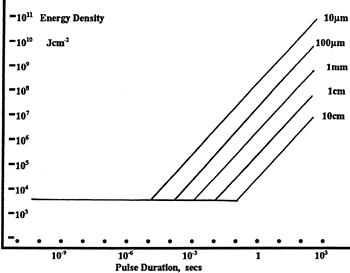
Figure 37G LIDT in energy density vs. pulse length and spot size. For short pulses, energy density becomes a constant with spot size. This graph was obtained from [1].
- Wavelength of your laser
- Energy density of your beam (total energy divided by 1/e2 area)
- Pulse length of your laser
- Pulse repetition frequency (prf) of your laser
- Beam diameter of your laser (1/e2 )
- Approximate intensity profile of your beam (e.g., Gaussian)
The energy density of your beam should be calculated in terms of J/cm2. Figure 37G shows why expressing the LIDT as an energy density provides the best metric for short pulse sources. In this regime, the LIDT given as an energy density can be applied to any beam diameter; one does not need to compute an adjusted LIDT to adjust for changes in spot size. This calculation assumes a uniform beam intensity profile. You must now adjust this energy density to account for hotspots or other nonuniform intensity profiles and roughly calculate a maximum energy density. For reference a Gaussian beam typically has a maximum energy density that is twice that of the 1/e2 beam.
Now compare the maximum energy density to that which is specified as the LIDT for the optic. If the optic was tested at a wavelength other than your operating wavelength, the damage threshold must be scaled appropriately [3]. A good rule of thumb is that the damage threshold has an inverse square root relationship with wavelength such that as you move to shorter wavelengths, the damage threshold decreases (i.e., a LIDT of 1 J/cm2 at 1064 nm scales to 0.7 J/cm2 at 532 nm):

You now have a wavelength-adjusted energy density, which you will use in the following step.
Beam diameter is also important to know when comparing damage thresholds. While the LIDT, when expressed in units of J/cm², scales independently of spot size; large beam sizes are more likely to illuminate a larger number of defects which can lead to greater variances in the LIDT [4]. For data presented here, a <1 mm beam size was used to measure the LIDT. For beams sizes greater than 5 mm, the LIDT (J/cm2) will not scale independently of beam diameter due to the larger size beam exposing more defects.
The pulse length must now be compensated for. The longer the pulse duration, the more energy the optic can handle. For pulse widths between 1 - 100 ns, an approximation is as follows:

Use this formula to calculate the Adjusted LIDT for an optic based on your pulse length. If your maximum energy density is less than this adjusted LIDT maximum energy density, then the optic should be suitable for your application. Keep in mind that this calculation is only used for pulses between 10-9 s and 10-7 s. For pulses between 10-7 s and 10-4 s, the CW LIDT must also be checked before deeming the optic appropriate for your application.
Please note that we have a buffer built in between the specified damage thresholds online and the tests which we have done, which accommodates variation between batches. Upon request, we can provide individual test information and a testing certificate. Contact Tech Support for more information.
[1] R. M. Wood, Optics and Laser Tech. 29, 517 (1998).
[2] Roger M. Wood, Laser-Induced Damage of Optical Materials (Institute of Physics Publishing, Philadelphia, PA, 2003).
[3] C. W. Carr et al., Phys. Rev. Lett. 91, 127402 (2003).
[4] N. Bloembergen, Appl. Opt. 12, 661 (1973).

Click to Enlarge
Figure 5.1 Edge-on View of the Quartz-Wedge Depolarizer
Operating Principle
Each Quartz-Wedge Achromatic Depolarizer is made of two wedged, birefringent plates with their fast axes oriented at 45° to one another. The 45° offset allows the plates to depolarize any input polarization state; light that is linearly polarized along the fast axis of one plate will still change polarization due to the birefringence of the other plate. Because the plates are wedged, the path length through each birefringent plate will vary based on the beam position, and each position on the aperture will have a net birefringence and final polarization state which are spatially dependent. For a sufficiently large beam, the output beam will resemble an unpolarized beam, though it would be more accurate to state that these optics give a fine spatial dependence to the polarization rather than truly depolarize it.
A monochromatic beam should be at least 6 mm in diameter in order to achieve significant depolarization across the area of the beam. Light from a broadband source does not have this same requirement because the effects of birefringence vary based on wavelength as well as the path length through the material.
Spatial Periodicity in the Polarization of the Output Beam
The spatial periodicity in the polarization of the output beam of the polarizer is easily observed when a linearly polarized monochromatic light source is used. The linearly polarized monochromatic beam must have a beam waist larger than 6 mm to generate this spatial periodicity. To observe this effect, place the quartz-wedge depolarizer in the beam so that propagation direction of the beam is normal to and incident upon the thicker wedge of the depolarizer.
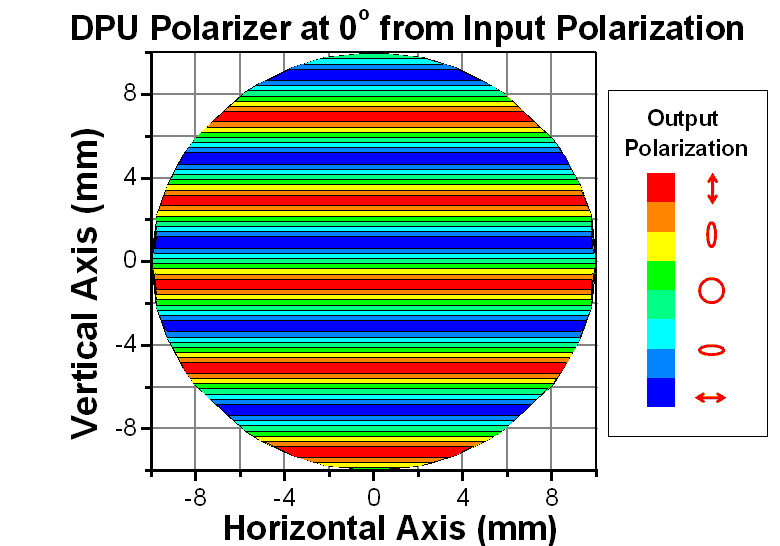
To detect the beam's spatial periodicity, place a linear polarizer (analyzer) after the beam exits the quartz-wedge depolarizer. The intensity variation will be banded as shown in the false-color plots shown in Figures 5.3, 5.5, and 5.7. The banding occurs because the degree to which the state of polarization is rotated is identical along any line perpendicular to the thick wedge incline. Several examples of different incident and depolarizer angles are discussed below.
Example 1:
In the first example, a 635 nm, linearly polarized source with a 20 mm beam waist is used. The source light is incident on and propogating normal to the thick wedge of the depolarizer. The light is polarized in the same direction as the optic (fast) axis of the thick wedge. The optic axis of the thin wedge is at a 45o angle with respect to both the incident light polarization and the optic axis of the thick wedge. In this orientation, the wedge incline is also oriented parallel to the incident light polarization.
The orientation of the input polarization and optic axis of the thick and thin wedges is shown in Figure 5.2. The input polarization is shown in red, the thick wedge optic axis in blue, and the thin wedge optic axis in green. The flat on the top of the depolarizer drawing (solid blue line) is cut perpendicular to the thick wedge optic axis. The flat on the side of the drawing (dashed blue line) is cut perpendicular to the thin wedge optic axis.
A theoretical plot showing the spatially-dependent polarization angle is shown in Figure 5.3. This false-color plot shows the polarization angle of the output beam from the quartz-wedge depolarizer based on the input beam characteristics described above.

The bands in the false-color plot represent different regions of identical polarization with polarizations varying from being completely along the horizontal axis (perpendicular to the input polarization) to completely along the vertical axis (parallel to the input beam polarization). The separation between the two polarizations in this case is approximately 2 mm. The orientation of the bands are always perpendicular with the thick wedge optic axis, and in this case, are also perpendicular to the input polarization.
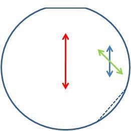
Figure 5.2 Input polarization in a parallel arrangement with the optic axis of the thick wedge.
Click to Enlarge
Figure 5.3 False-color plot of a calculation showing a linearly polarized input beam parallel to the optic axis of the thick wedge after passing through the depolarizer.
Example 2:
In this example, the same linearly polarized source is used, except the polariation is oriented parallel to the optic axis of the thin wedge and at a 45 degree angle from the optic axis of the thick wedge. The orientation of the input polarization and optic axes of the thick and thin wedges are shown in Figure 5.4. The input polarization is shown in red, the thick wedge optic axis in blue, and the thin wedge optic axis in green. The flat on the top of the depolarizer drawing (solid blue line) is cut perpendicular to the thick wedge optic axis. The flat on the side of the drawing (dashed blue line) is cut perpendicular to the thin wedge optic axis.
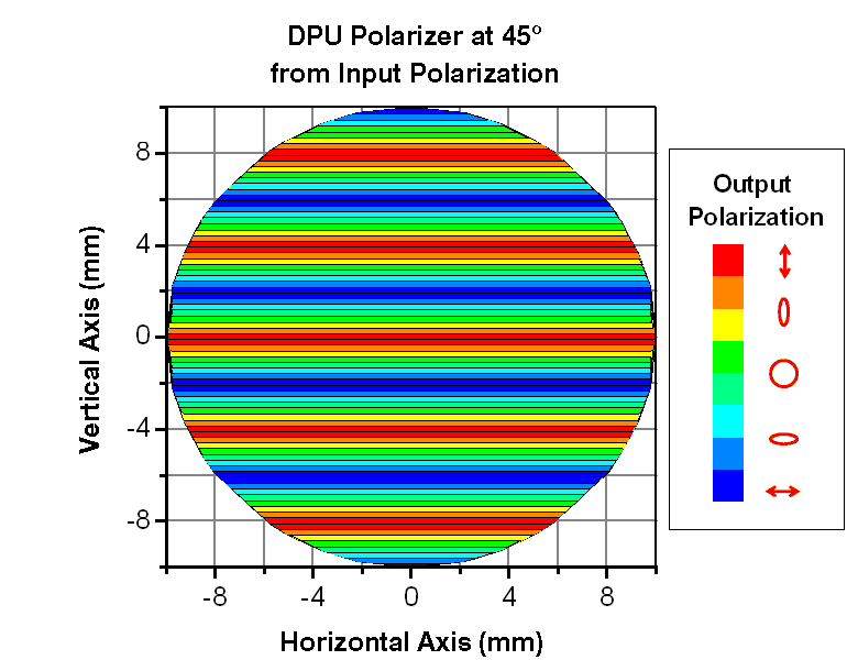
The calculated result for the source and orientation passing through the quartz-wedge depolarizer is shown in Figure 5.5. As described in Figure 5.3, the bands in the false-color plot represent the the spatially-dependent regions of identical polarization. Note the orientation of the banding is perpendicular to the optic axis of the thick wedge (and wedge incline as well). The orientation of the input beam has no effect on the orientation of the banding.
Rotating the input polarization only affects the specific polarization of the band. This is easily observed by comparing the bands at 0 mm on the vertical axis in Figures 5.3 and 5.5. In Figure 5.3, the band at 0 mm has a 45o orientation while in Figure 5.5, the band at 0 mm has a 90o orientation.
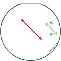
Figure 5.4 Input polarization in a parallel arrangement with the
optic axis of the thin wedge.
Click to Enlarge
Figure 5.5 False-color plot of a calculation showing a linearly polarized input beam parallel to the optical axis of the thin wedge after passing through the depolarizer.
Example 3:
In this last example, the input beam has the same characteristics as in Example 1. However, the quartz-wedge depolarizer is rotated 45o so the input polarization is parallel to the optic axis of the thin wedge. This arrangement is shown in Figure 5.6. The input polarization (red arrow) is still incident on the thick wedge; however, it is now perpendicular to the thin wedge flat.
The false-color plot in Figure 5.7 shows the calculation result of the input beam described above passing through the quartz-wedge depolarizer. The orientation of the banding is clearly different from the banding in Figures 5.3 and 5.5. The 45o tilt in the pattern is because the banding occurs perpendicular to both the optic axis of the thick wedge and wedge incline.
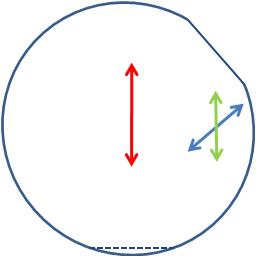
Figure 5.6 Input polarization in a parallel arrangement with the
optic axis of the thin wedge and 45o to the wedge plane.
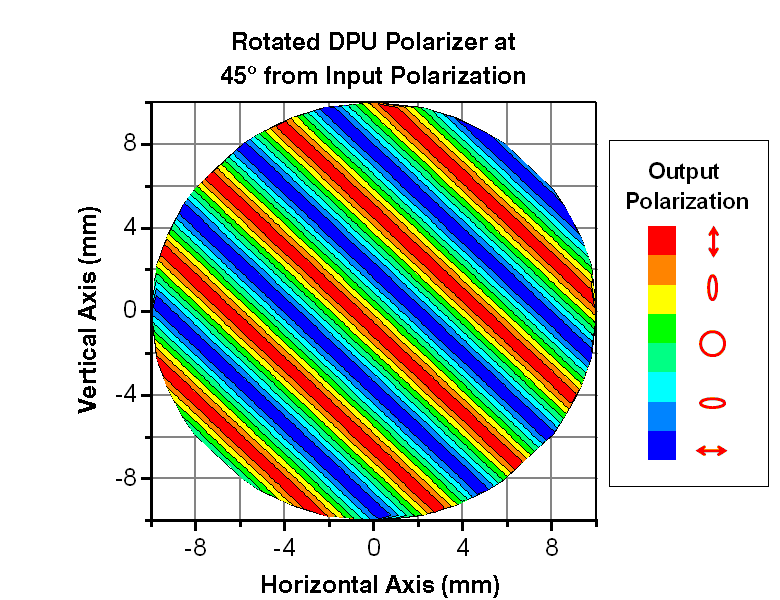
Click to Enlarge
Figure 5.7 False-color plot of a calculation showing a linearly polarized input beam parallel to the optic axis of the thin wedge after passing through the depolarizer at a 45o angle to the wedge plane.
| Posted Comments: | |
Michal Jiránek
(posted 2025-02-11 08:27:06.643) Hello,
please do you have on hand / can you provide me with DOP of the depolarizer (DPU-25 uncoated) for larger beam sizes (upto a full aperture ideally) at 0° AOI at 630nm?
Next it would be great if you could provide me with the method / explanation how do you do the measurement of the DOP for these depolarizers.
Thanks in avdavce for the answer.
Kind regards,
Jiránek jdelia
(posted 2025-03-27 08:23:49.0) Thank you for contacting Thorlabs. We would suggest checking out the "Tutorials" tab on the product family page as this reasonably conveys the performance with a 20 mm diameter beam. I have reached out to you directly to discuss methods of measurement for DOP for these depolarizers. Tzu-Lun Wang
(posted 2024-10-10 07:11:32.177) Hi,
Is it possible for Thorlabs to provide a single-piece Quartz wedge with AR coating instead of a cemented one?
Thank you for the answering jpolaris
(posted 2024-10-18 05:11:52.0) Thank you for contacting Thorlabs. Requests for customizations can be made by reaching out to our technical support team that is local to your region. Our global contacts list can be found at the link below. I have reached out to you directly for clarification about what you are requesting. https://www.thorlabs.com/support.cfm Charles Stark
(posted 2023-09-15 21:41:08.053) Why did you discontinue the Lyot Depolarizer series?
It's hard to find optics that depolarize according to the spectral domain, rather than spatial. jdelia
(posted 2023-09-18 12:55:24.0) Thank you for contacting Thorlabs. We apologize for any inconvenience caused by the fact that we no longer sell this. I have reached out to you directly to discuss the reason for obsolescence. Lian Xiang
(posted 2020-10-04 07:56:53.94) Sir:
May I ask two questions?
1. Why the thickness of two quartz needs has a ratio 1:2?
2. Can make a depolarizer with two wedged quartz, and their crystal axis is 45 degrees from horizontal surface in different direction, make them perpendicular each other?
Lian YLohia
(posted 2020-10-05 11:14:48.0) Hello Lian, it appears that you have emailed and called us already. We will discuss this directly via email. sarayuyammanuru
(posted 2018-03-22 14:22:17.913) Hello, I have gone through the information on this page but it did not find the exact working principle DPU -25 depolariser. Can you please brief it? Thank you tfrisch
(posted 2018-03-23 09:23:10.0) Hello, thank you for contacting Thorlabs. Without getting too far into the design or mathematics of these depolarizers, each one is made of two birefringent, wedged plates. Because they are wedged, the amount of birefringence depends on the position of the beam. Furthermore, the two plates have optic axes which are rotated by 45 degrees with respect to each other. Since birefringence adds geometrically, each position on the aperture will have a net-birefringence and optic-axis-orientation which are each spatially dependent on the position of the beam on the aperture of the depolarizer. For a large beam, the output beam will behave similarly to an unpolarized beam. However, it would be more correct to state that these optics give a fine spatial dependence to polarization rather than truly depolarize it. I will reach out to you directly to discuss any further questions you may have. inzenith
(posted 2017-07-04 00:14:00.04) Hello. You've explained about single mode fiber in Fiber Applications section, can i use this product for multimode mode Fiber? thank you tfrisch
(posted 2017-08-04 10:05:07.0) Hello, thank you for contacting Thorlabs. While you would be able to use a quartz depolarizer with multimode fiber, you likely would not need to as modes in the multimode fiber would already have different polarization states leading to a very complex spatial dependence on polarization state on the fiber output. I will reach out to you directly to discuss this further. aayeb
(posted 2017-03-20 10:55:52.867) Dear Thorlabs team,
Would you have LIDT values for the component DPU-25-C at 1064nm in CW?
I might use it with a rectangular beam of 1mm x 10mm with a 100W power.
Thanks for your answer,
Adam tfrisch
(posted 2017-03-30 10:18:52.0) Hello, thank you for contacting Thorlabs. While we don't have a formal CW damage threshold for these, I will reach out to you directly your source. My biggest concern is actually the beam size as it is smaller than 6mm in one dimension. A depolarizer will give the beam a spatial dependence on the polarization as a polarized source will never be truly depolarized. I will reach out to you to discuss this as well. aayeb
(posted 2016-07-19 14:40:29.457) As explained in the product description, a deviation caused by the birefringence appears with this kind of depolarizers. Would you have a value for this deviation at 532nm?
Thank you cverge
(posted 2015-08-31 16:06:34.937) You seem to have much data on the narrow band varieties of DPU-25 (a,b,c) but none on the uncoated version DPU-25 except its transmission.
Can I get plots of DOP v.s wavelength and beam size for the uncoated DPU-25 ?
Thanks,
Clarence Verge
Engineering Manager
Sciencetech Inc. besembeson
(posted 2015-09-02 01:28:47.0) Response from Bweh at Thorlabs USA: We have not measured the uncoated ones yet. But they will have similar performance as the coated ones, except for the % reflection and transmission. mike.atlas
(posted 2015-02-12 15:03:34.493) Is there a specification for the overall optical wedge for the DPU-25.
Since the DPL-25 is constructed from two opposing wedges there should be some residual wedge from misalignment of the wedge angles around the optical axis and the tolerance on the wedge angles.
The residual optical wedge would deflect the incident beam. Is the re a spec for the maximum beam deviation angle? besembeson
(posted 2015-02-18 07:55:39.0) Response from Bweh at Thorlabs USA: The design and alignment intent for these units is best depolarization, and not best beam deviation. The wedge error of individual components could be as much as 3-4 min. Cumulative errors of wedges, spacer and alignment could yield a wedge of 10 min for outer surfaces and an approximately 5 min beam deviation. mike.atlas
(posted 2013-03-11 09:58:18.607) I your descriptions of polarization optics the word OPTICAL axis is used erroneously. Instead OPTIC axis should be used. See below:
"OPTIC AXIS is an optical path through a crystal along which a ray of light can pass without undergoing double refraction"
"optic axis - in a doubly refracting crystal, the line in the direction of which no double refraction occurs; "a crystal may have either one or two optic axes""
"Optic axis the direction in a uniaxial crystal or one of the two directions in a biaxial crystal along which a ray of unpolarized light may pass without undergoing double refraction" sharrell
(posted 2013-03-12 09:48:00.0) Response from Sean at Thorlabs: Thank you for your feedback. We've updated our depolarizer presentation to properly say "optic axis" where appropriate, and I'll check our other crystalline optic pages in the coming days to ensure we haven't made the same error elsewhere. kongfanhe
(posted 2012-07-14 20:03:01.0) Dear Sir/Madam:
We have bought a DPU-25, and we found that the period of the interference pattern is 2mm (for polarization state plot, in the example 1 of the tutorial), instead of 4mm.
Could you help me to verify if the period of the false-color plot in that example is really 2mm?
Kind regards,
Frank kongfanhe
(posted 2012-07-14 13:42:36.0) Dear Sir/Madam:
We have bought a DPU-25, and we found that the period of the interference pattern is 2mm (for polarization state plot, in the example 1 of the tutorial), instead of 4mm.
Could you help me to verify if the period of the false-color plot in that example is really 2mm?
Kind regards,
Frank bdada
(posted 2012-03-16 19:23:00.0) Response from Buki at Thorlabs to m.kulkarni88:
Thank you for your feedback. The diameter of the DPU-25 depolarizer is 25.4mm, so it should work well for your 5 x 7mm beam. We have contacted you to discuss any other concerns you may have about using this depolarizer. m.kulkarni88
(posted 2012-03-13 17:06:50.0) I am trying to depolarize the light at the exit slit of a monochromator. The 8-12nm wide light beam is rectangular, of size approximately 5mm by 7mm at the output slit. Will this depolarizer be effective at its job given these parameters? Thanks. jjurado
(posted 2011-03-28 19:02:00.0) Response from Javier at Thorlabs to cristoph.hauri: Thank you very much for contacting us with your request. The substrate of these achromatic depolarizers is crystal quartz, which yields a transmission for our uncoated DPU-25 polarizer >80% at 260 nm. It should also work with pulse widths of 1-2 nm; however, make sure that the damage threshold of the optic is not exceeded (100 W/cm^2). We currently do not have dispersion data, but I will look into this and get back to you. christoph.hauri
(posted 2011-03-28 18:48:21.0) is the product working around 260nm? is the substrate UV grade fused silica? IF not, would it be possible to order one made out of UV FS? how much dispersion is expected? the bandwidth of our pulse is 1-2 nm. Would this device work? Thorlabs
(posted 2010-08-27 14:53:15.0) Response from Javier at Thorlabs to dashamstyr: Thank you for your feedback. As mentioned on the Overview section, there is a non-zero divergence/offset associated with the DPUs. The reason is that since the optical axes of the wedges are not aligned, the output beam basically consists of two superimposed beams, each with different propagation vectors. This offset is,for the most part, negligible for freespace applications, but can create difficulties when cupling into single mode fiber. dashamstyr
(posted 2010-08-26 13:56:57.0) Do these depolarizers introduce any deviation to the beam axis? If so, how much can I expect for monochromatic light at 532nm? Response
(posted 2010-07-30 11:53:26.0) Response from Javier at Thorlabs to k1w05: Thank you for your feedback. Unfortunately, we do not have a damage threshold spec for pulsed input. We are currently embarking on a project to test the CW and pulsed damage specs for most, if not all, of our optics. As a guideline, with a ~24mm beam diameter, the maximum power input should be limited to ~450 W. Based on the pulse width of your source, you can calculate the peak power, which should not exceed this value. I will let you know as soon as we have the results for the DPU-25, and we will post them on the web. k1w05
(posted 2010-07-29 16:10:40.0) In the specification table of DPU-25, just CW threshold is given. Im wondering the threshold of pulse laser. My lasers rep. rate is 20Hz, wavelength 532nm, pulse energy about 100mJ, beam diameter 24mm after beam expanding. Thank you! klee
(posted 2009-11-06 10:29:51.0) A response from Ken at Thorlabs to robert.brown: The plots on this web page are for our current stock. The plots on our new V20 catalog are for our future stock which we should have in a few weeks. robert.brown
(posted 2009-11-05 09:20:23.0) The broadband coatings for this product seem to be different for the plots tab and what is presented in the catalogue. Can you confirm which is correct?
thanks apalmentieri
(posted 2009-05-26 10:13:33.0) A response from Adam at Thorlabs: The depolarizers are made with two pieces of quartz wedges that are epoxied together. As the polarized light passes through the quartz, the polarization state of the light will change. Since the quartz pieces are wedged, the path length of the light at each point in the beam will be different along the axis of the wedge. This difference in path length causes a layering effect in the polarization states, which is responsible for the periodical banding. As the path length increases over the beam diameter so the polarization state rotates through 2Pi retardance, you will notice that the banding pattern repeats itself. ningjq
(posted 2009-05-26 09:05:09.0) I can not understand the tutorial named "Spatial Periodicity in the Polarization of the Output Beam of a Monochromatic Beam of Light" upon the DPU depolarizer. Could you please tell me the physical origin of the periodical banding? Tyler
(posted 2008-12-04 11:23:58.0) A response from Tyler at Thorlabs: All the cemented depolarizers have been discontinued (search for WDPOL or LDPOL for information). The DPU series of depolarizers have an air gap between the two optics. This design makes them suitable for high-power applications (100 W/cm^2 damage threshold). Tyler
(posted 2008-04-14 13:30:20.0) Response from Tyler at Thorlabs to hagaie: The DPU series of depolarizers will work with monochromatic light sources (i.e., the depolarization of the linearly polarized incident beam is not dependent on its spectral width, only the physical diameter of the beam). hagaie
(posted 2008-04-13 08:52:34.0) How wide should be the input spectral width in order to get best results? technicalmarketing
(posted 2007-10-17 08:59:44.0) We apologize for this contradiction. These depolarizers feature cemented optics, making them sufficient for low-power applications. We have updated the presentation to reflect this information and apologize for any confusion we may have caused. tnakai
(posted 2007-10-16 20:05:03.0) It says "opticalyy contacted," but also says "cemented." Which is right ? |
 Products Home


 Quartz-Wedge Depolarizers