 Products Home
Quantum Eraser Demonstration Kit
- Designed for Education, Demonstration, and Classroom Use
- Easy-to-Use Kits Include Components Plus Free Educational Materials


Please Wait

Click to Enlarge
Figure 1.1 Interference fringes are only shown on the left viewing screen, where the path information has been "erased."

Quantum Eraser Analogy Demonstration Kit
- Designed for Educational, Demonstration, and Classroom Use
- Complete Kit Includes All Hardware Plus Extensive Manual and Teaching Materials
- Easy to Assemble and Use
- Choose from Kits Containing Imperial or Metric Components
Experiment
- Photons Create an Interference Pattern in a Mach-Zehnder Interferometer
- Demonstrates Complementarity of Particle/Wave Duality of Light
- Polarization "Marks" and "Erases" Each Photon's Path Information
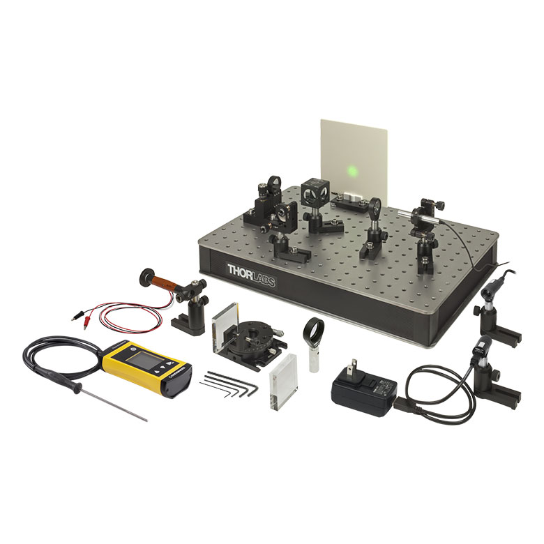
Thorlabs' Quantum Eraser educational lab kit shows through analogy the quantum-mechanical principle of complementarity and the erasure of path information. Designed to show the fundamental principles of quantum physics, this experiment clearly displays how nature is often counterintuitive on the quantum scale.
An instructional video showing the assembly and alignment of the kit components is available in the Alignment Video tab.
Thorlabs Educational Products
Thorlabs' educational line of products aims to promote physics, optics, and photonics by covering many classic experiments, as well as emerging fields of research. Each educational kit includes all the necessary components and a manual that contains both detailed setup instructions and extensive teaching materials. These lab kits are being offered at the price of the included components, with the educational materials offered for free. Technical support from our educational team is available both before and after purchase.
Purchasing Note: English and German language manuals/teaching information are available for this product. The imperial kit contains the English manual. The power supply and other electronic devices in both the metric and the imperial kit accept voltages of 230 VAC or 120 VAC. See the respective manuals for details. The appropriate manual will be included in the metric kit based on your shipping location. Please contact Tech Support if you need a different language or power supply. As with all products on our website, taxes are not included in the price shown below.

Click for Details
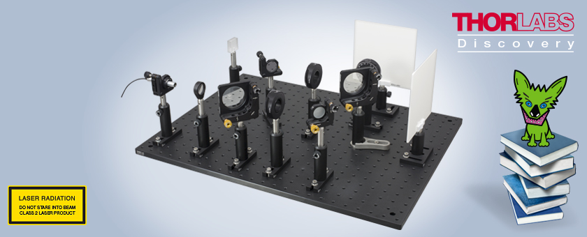
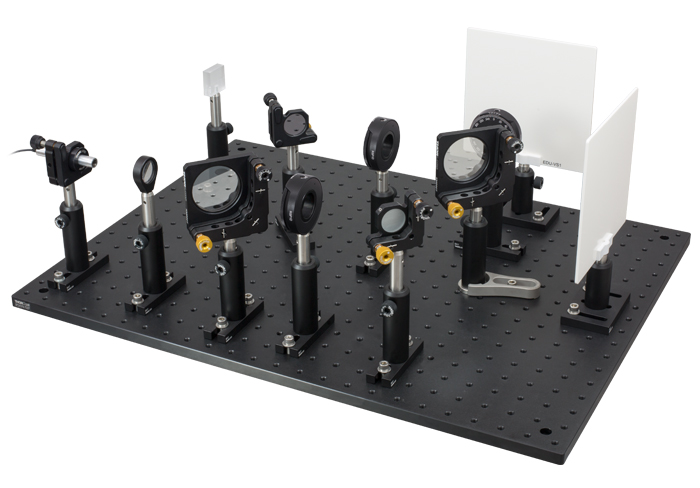
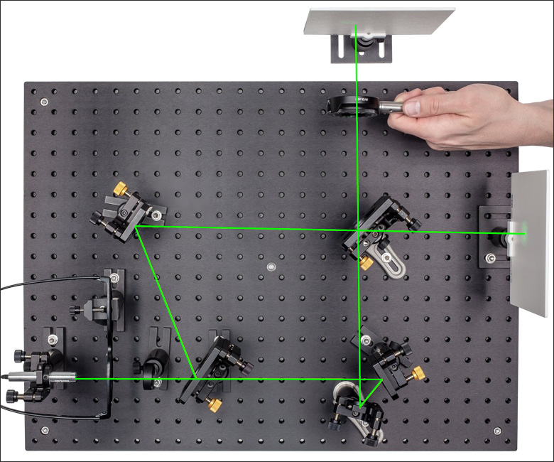
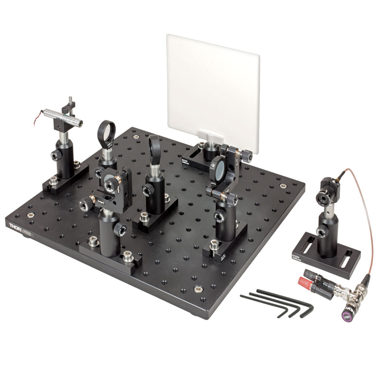
Figure 2.1 Quantum Eraser Demonstration Optical Components and Beam Path
Summary
In the quantum eraser experiment, single photons are emitted into a Mach-Zehnder interferometer. Using linear polarizers, the photons are "marked" as having either a horizontal or vertical polarization state, indicating which side of the interferometer they have traveled through. The interference pattern (wave property) and path information (particle property) cannot be measured simultaneously, since measuring the path information destroys the interference pattern. A third linear polarizer, placed after the beams have been recombined, "erases" the path information, making the photons anonymous again, and thus restoring the interference pattern.
Rather than using single photons, as in the original quantum eraser experiment, this kit uses a green continuous-wave (CW) laser light source that produces a beam that is visible to the eye. While the outcome of the experiment can be explained using classical physics, using a quantum-mechanical description provides a perfect analogy to the single-photon quantum eraser experiment.
The Quantum Eraser Experiment
The quantum eraser experiment demonstrates the quantum-mechanical principles of complementarity, path information, and superposition. An interferometer can be used to demonstrate the wave nature of light, by creating two optical paths that have slightly different path lengths. According to the classical interpretation, light strikes a viewing screen after traveling along the two paths in the interferometer. If the difference in path lengths is equal to an integer number of waves, a bright spot is produced through constructive interference, and if the path length difference is equal to an odd number of half waves, a dark spot is produced through destructive interference. Since all light rays traveling through the system do not travel an equivalent path length due to the lens, a bullseye interference pattern is produced.
Interference experiments can also be performed with light sources that emit a single photon at a time. A classical interpretation would predict that as the single photon passes through the interferometer, it is presented with a choice of which path to follow, and an interference pattern is not created since all of the light travels through one path. However, a classical interpretation cannot be applied to an experiment performed with single photons, and it will not predict accurate results.
According to the quantum-mechanical interpretation of the experiment, the photon has two possible states in the interferometer, corresponding to the photon in the first arm, and the photon in the second arm. The wavefunctions of these states are superimposed and interfere, and the result is that the photon will only strike the screen in a location where bright fringes would be expected if multiple photons were present. A single photon cannot reproduce an entire interference pattern by itself, but if many single photons are recorded over a period of time, the cumulative result is an interference pattern that is identical to one produced by a standard interference experiment.
On a quantum-mechanical scale, certain pairs of information cannot be determined simultaneously. For instance, the Heisenberg uncertainty principle states that the more precisely one knows the position of a particle at a given time, the less precisely one can know the momentum. If information exists (even if it is not measured by a conscious observer) that reveals one property (in this case, which path the photon traveled), then each particle will exhibit no wave interference, as the superpositioning of wavefunctions is destroyed. But if no information exists about one measurement, the wavefunctions of the photon’s different states superimpose, thereby creating the interference pattern. Additionally, if information exists that reveals one property, but then that information is destroyed, or "erased" (so that the path information can no longer be observed), the particles will again exhibit wave interference.
Thus, the result of the single photon interferometer is altered if the experimenter attempts to measure which path the photon followed. If the path measurement is performed, there are no longer two states to interfere, and the photons no longer produce the interference pattern; instead, they create a single, large spot on the screen. However, if the path information is "erased" so that it cannot be measured, the interference pattern returns.
Thorlabs Quantum Eraser Demonstration
The Thorlabs quantum eraser demonstration is an analogy to the original single-photon quantum eraser experiment but uses a continuous beam of photons that is visible to the naked eye. A Mach-Zehnder interferometer and a green laser diode are employed to create an interference pattern that is viewed on two screens, as shown in Figure 2.1. A linear polarizer in each of the two signal paths allows either horizontally or vertically polarized light to pass through it, providing information about which path a given photon has traveled. As expected, the interference pattern disappears. A third polarizer, placed after the beams have been recombined, and set at 45° to each of the first two polarizers, serves to "erase" the path information, and the interference pattern reappears. While these results can be explained by classical properties of light polarization, the quantum-mechanical explanation serves as an analogy to the single photon experiment.
Assembly and Alignment of the Mach-Zehnder Interferometer
This instructional video provides step-by-step instructions on the positioning and alignment of key components in the Thorlabs’ EDU-QE1(/M) Quantum Eraser Demonstration kit. In the video, you can see how the Mach-Zehnder interferometer is aligned. This video supplements the comprehensive instructions provided in the manual.
| Table 4.1 Included Components | ||
|---|---|---|
| Item # | Description | Qty. |
| CPS532-C2 | Green Laser Module | 1 |
| DS5 | 5 VDC Power Supply for Laser | 1 |
| CPSA | USB 2.0 Type-A to 2.5 mm Phono Cable for Power Supply to Laser | 1 |
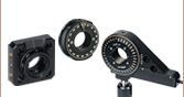
| KM100 | Kinematic Ø1" Mirror Mount | 3 |
| AD11NT | Ø2" (50.8 mm) Unthreaded Adapter for Ø11 mm Cylindrical Components | 1 |
| LB1901 | Ø1" Bi-Convex Lens, 75 mm Focal Length |
1 |
| LMR1 (LMR1/M) |
Ø1" Fixed Lens Mount | 1 |
| EBS2 | Ø2" 50:50 Beamsplitter | 2 |
| KM200T | Ø2" Adjustable Beamsplitter Mount | 2 |
| LPVISE2X2 | Linear Polarizing Film (Cut into Three Ø1" Circles) |
1 |
| RSP1D (RSP1D/M) |
Rotation Mount for Ø1" Optics | 3 |
| ME1-G01 | Ø1" Aluminum Mirror | 2 |
| EDU-VS1 (EDU-VS1/M) |
Observation Screen | 2 |
| TR3 (TR75/M) |
Ø1/2" (Ø12.7 mm) Mounting Post, 3" (75) mm Long | 10 |
| TR2 (TR50/M) |
Ø1/2" (Ø12.7 mm) Mounting Post, 2" (50 mm) Long | 2 |
| PH3 (PH75/M) |
Ø1/2" (Ø12.7 mm) Post Holder, 3" (75 mm) Long |
9 |
| PH2 (PH50/M) |
Ø1/2" (Ø12.7 mm) Post Holder, 2" (50 mm) Long |
2 |
| PH3E (PH75E/M) |
Ø1/2" (Ø12.7 mm) Pedestal Post Holder, 3.19" (80.9 mm) Long | 1 |
| BA1 (BA1/M) |
Mounting Base, 1" x 3" x 3/8" (25 mm x 58 mm x 10 mm) |
8 |
| BA1S (BA1S/M) | Small Mounting Base, 1" x 2.3" x 3/8" (25 mm x 58 mm x 10 mm) | 1 |
| BA2 (BA2/M) |
Mounting Base, 2" x 3" x 3/8" (50 mm x 75 mm x 10 mm) |
2 |
| CF125 | Clamping Fork 1.24" (31.5 mm) Counterbored Slot | 1 |
| AT1 (AT1/M) | Acrylic Alignment Tool, 1.18" x 1.18" (30.0 mm x 30.0 mm) | 1 |
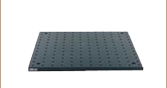
| MB1824 (MB4560/M) |
Aluminum Breadboard, 18" x 24" (45 cm x 60 cm) |
1 |
| RDF1 | Rubber Breadboard Feet (Not Shown) |
4 |
| SM1RR | Ø1" Retaining Ring | 1 |
| F25SSK1-GOLD | Gold Colored Adjustment Knobs | 4 |
| SPW606 | SM1 Spanner Wrench, 1" (25.4 mm) Long |
1 |
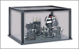
Quantum Eraser Kit Components
Mouse over the photo to see the corresponding components in Table 4.1.
The Thorlabs Quantum Eraser demonstration kit has been carefully engineered to be easy to set up and to give clear, reliable results. The kit contains many stock Thorlabs components, making it possible to expand the scope of the experiment by purchasing additional components.
Note: English and German language manuals/teaching information are available for this product. The imperial kit contains the English manual. The power supply and other electronic devices in both the metric and the imperial kit accept voltages of 230 VAC or 120 VAC. See the respective manuals for details. The appropriate manual will be included in the metric kit based on your shipping location. Please contact Tech Support if you need a different language or power supply. As with all products on our website, taxes are not included in the price shown below.
Imperial Kit: Included Hardware and Screws
| Item # | Description | Qty. |
|---|---|---|
| SH25S050a | 1/4"-20 x 1/2" Long Cap Screw | 11 |
| SH25S063a | 1/4"-20 x 5/8" Long Cap Screw | 21 |
| SH25S075a | 1/4"-20 x 3/4" Long Cap Screw | 4 |
| - | 1/4" Nut | 4 |
| W25S050 | 1/4" Washer | 21 |
| BD-3/16L | 1/4"-20 Ball Driver | 1 |
| - | 1/16" Hex Key | 1 |
| - | 5/64" Hex Key | 1 |
| - | 9/64" Hex Key | 1 |
User-Generated Content
Thorlabs' Educational Kits allow users to adapt the content to their own teaching needs. With that in mind, we enjoy hearing feedback from our customers with details about how they use the kits in their own classrooms. Use the Contact Us button if you would like to submit your own user-generated content.
Pancharatnam's Phase Demonstration
We cordially thank Professor Surendra Singh, University of Arkansas, for sending us the following modification of the EDU-QE1 to demonstrate Pancharatnam’s phase of light.
Theory
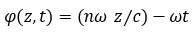
Electromagnetic waves have both a polarization state and a dynamical phase that must be taken into account when considering the effects of propagation through material media. An electromagnetic plane wave of angular frequency ω propagating in the z-direction can be represented by its electric field:
![]()
In this equation, the dynamical phase is represented by
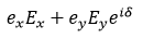
where n is the refractive index of the medium and c is the speed of light. φ0 represents the initial or reference phase. The polarization state of the wave is determined by the relative magnitudes and phase difference of the x and y components of the electric field vector, captured by this part of the equation:
where δ is the relative phase difference between Ex and Ey. If the polarization state of the wave changes during propagation, the wave may acquire an extra contribution to its phase in addition to the change in its dynamical phase. This phase contribution is referred to as Pancharatnam's phase of light (also known as Pancharatnam-Berry phase).1
Additional Items Needed (Metric Versions in Parentheses)
|
To Create Circularly Polarized Input: |
To Add the Extra Mirror: |
Experiment
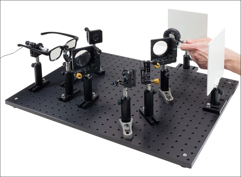
Pancharatnam's phase can be observed by making some minor modifications to the Mach-Zehnder interferometer in the Quantum Eraser Demonstration Kit. Circular polarization is required, so a linear polarizer and a quarter-wave plate must be added between the laser source and the first lens in the setup. An inexpensive way to achieve this is to use a pair of 3D movie glasses, such as the RealD™ 3D Glasses included in our Polarization and 3D Cinema Technology Kit; versions of these glasses can also be easily found and purchased online.
Click to Enlarge
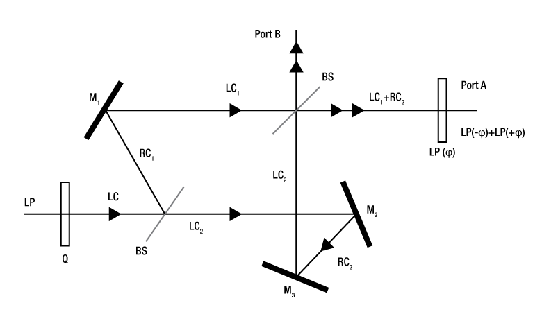
Figure 5.2 The Mach-Zehnder Interferometer in the EDU-QE1 is modified to show Pancharatnam's phase by adding a pair of 3D glasses to circularly polarize the light, an extra mirror, and a linear polarizer.
Click to Enlarge
Figure 5.1 A Mach-Zehnder interferometer can be modified to show Pacharatnam's phase by adding an extra mirror to one arm.
M = Mirror, BS = Beamsplitter, Q = Wave Plate, LP = Linear Polarizer
LC = Left Circular Polarization, RC = Right Circular Polarization
When circularly polarized light is reflected off of either a mirror or a beamsplitter, it is converted to the opposite polarization state: at each reflection, left circularly polarized light becomes right circularly polarized or right circularly polarized light becomes left circularly polarized. In a typical Mach-Zehdner interferometer, the light in each arm undergoes the same number of reflections, so the light from each arm of the interferometer is in the same polarization state after it is recombined by the final beamsplitter before Port A (or Port B).
To observe Pancharatnam's phase, an extra mirror is added to one arm to introduce an additional reflection, which corresponds to an additional polarization-state change in that arm. The path lengths along the two arms of the interferometer are set to be exactly equal, removing any contribution from the dynamical phase. The schematic in Figure 5.1 traces the change of the polarization state at each reflection as light travels through the interferometer. As a result of these reflections, the output light at Port A or Port B is a combination of right circularly polarized light from one arm of the interferometer and left circularly polarized light from the other arm. At this point, no fringes will appear at Port A or Port B since the light from one arm is in a polarization state orthogonal to the light from the other arm.
Click to Enlarge
Figure 5.4 The linear polarizer must be hand-held in front of the viewing screen for the experiment to work. If it is mounted on the breadboard, rotating the polarizer will introduce vibrations that obscure the interference pattern.
Video 5.3 The interference fringes shift as the linear polarizer is rotated.
Placing a linear polarizer in front of Port A or Port B will cause an interference pattern to appear on the screen. The polarizer selects the components of the right circularly and left circularly polarized light that are parallel to the polarizer's transmission axis. If the polarizer is placed with its transmission axis at an angle φ to the x axis, the light from the two arms of the interferometer emerges from the linear polarizer as two linearly polarized coherent beams with the same polarization state and a relative phase difference of 2φ. This generates an interference pattern that can be observed on the screen.
As the linear polarizer is rotated, the fringes will shift even though the path difference between the two arms of the interferometer has not changed, which means that the dynamical phase is not contributing to the change in the interference pattern. The fringe shift is entirely generated by the difference in polarization state between the light from the two arms of the interferometer, which translates into a difference in phase after the light passes through the linear polarizer. This phase difference is an example of Pancharatnam's phase.
Tips for Aligning the Setup:
- When setting up this modified Mach-Zehnder interferometer, recall that the interference pattern becomes smaller in diameter when the path length difference between the interferometer arms increases. Try to have almost equal path lengths in both arms to make the pattern easier to view.
- In practice, the mirror in the upper arm must be placed asymmetrically to introduce as small a difference in path length as possible (i.e. not in 45° with respect to the incident laser beam).
- Interference is only visible when a linear polarizer is placed in front of the screen (as explained above).
- To adjust the alignment of the setup, we recommend using the beam walk method described in Step 10 (c) of Chapter 4.3.3 in the EDU-QE1 manual.
- The linear polarizer used to view the change in the interference pattern must be handheld for the experiment to work. Otherwise, vibration will obscure the interference pattern when the polarizer is rotated.
Professor Singh has written a detailed explanation of the experiment including Jones vector calculations of the phase, which can be downloaded here.
1S. Pancharatnam, Proc. Ind. Acad. Science A44, 247 (1956), also in Collected Works of S. Pancharatnam (Oxford U. Press, Oxford 1975).
Interferometer Demonstration Kit Comparison
Thorlabs offers three demonstration kits that make use of an interferometry setup. Each kit is designed to target a different topic and includes accessories to support the experiments described in the kit manual. The EDU-MINT2 interferometer kit is designed to explore the experimental uses of a Michelson Interferometer, while the EDU-BT1 and EDU-QE1 analogy demonstrations are designed to explore concepts in quantum mechanics. Due to the nature of the experiments in the EDU-MINT2 kit, an intrinsically damped breadboard is included to minimize vibrations as students interact with the setup. This added feature supports some of the more challenging experiments, especially the wavelength measurement and white light interference exercises. The other two demonstration kits are built on lighter, aluminum breadboards as the experiments outlined in these kits require less interaction with the setups and vibration is therefore less of an issue. Table 6.1 outlines the key features and educational topics addressed by each kit to aid in choosing the best option for your classroom.
| Table 6.1 Kit Comparison | |||
|---|---|---|---|
| Interferometer Type | Michelson | Mach-Zehnder | |
| Kit Item # | EDU-MINT2(/M) | EDU-BT1(/M) | EDU-QE1(/M) |
| Description | Michelson Interferometer Demonstration Kit | "Bomb Tester" Demonstration Kit | Quantum Eraser Demonstration Kit |
| Kit Photo (Click to Enlarge) |
 |
 |
 |
| Underlying Concept | Use a Michelson Interferometer as a Sensitive Instrument for Measuring Physical Properties |
Explore the "Bomb Tester" Thought Experiment with an Analogy Demonstration |
Explore the Dual Particle/Wave Nature of Light with an Analogy Demonstration |
| Light Sources | Laser (Class 2), Red LED, White LED | Laser (Class 2) | Laser (Class 2) |
| Breadboard | Steel Breadboard, 12" x 18" (30 cm x 45 cm) with Intrinsic Damping to Decrease the Effect of Vibrations |
Aluminum Breadboard, 12" x 12" (30 cm x 30 cm) | Aluminum Breadboard, 18" x 24" (45 cm x 60 cm) |
| Other Accessories |
Additional Beamsplitter to Observe Second Interferometer Output Plexiglas® Plates and Rotation Mount for Refractive Index Measurements Aluminum Rod, Heater, and Thermometer for Thermal Expansion Coefficient Measurement |
Detector for Measuring the Probability of Different States in the Analogy Experiment |
Polarizers to Observe the Effect of Polarization on the Interference Pattern |
| Educational Aspects |
|
|
|
Kit Conversion
Converting the EDU-MINT2(/M) kit to enable the demonstrations outlined in the EDU-BT1(/M) manual is simple; only a photodetector and the necessary mounting hardware are needed.
Laser Safety and Classification
Safe practices and proper usage of safety equipment should be taken into consideration when operating lasers. The eye is susceptible to injury, even from very low levels of laser light. Thorlabs offers a range of laser safety accessories that can be used to reduce the risk of accidents or injuries. Laser emission in the visible and near infrared spectral ranges has the greatest potential for retinal injury, as the cornea and lens are transparent to those wavelengths, and the lens can focus the laser energy onto the retina.
 |
 |
 |
 |
 |
 |
 |
 |
 |
Safe Practices and Light Safety Accessories
- Laser safety eyewear must be worn whenever working with Class 3 or 4 lasers.
- Regardless of laser class, Thorlabs recommends the use of laser safety eyewear whenever working with laser beams with non-negligible powers, since metallic tools such as screwdrivers can accidentally redirect a beam.
- Laser goggles designed for specific wavelengths should be clearly available near laser setups to protect the wearer from unintentional laser reflections.
- Goggles are marked with the wavelength range over which protection is afforded and the minimum optical density within that range.
- Laser Safety Curtains and Laser Safety Fabric shield other parts of the lab from high energy lasers.
- Blackout Materials can prevent direct or reflected light from leaving the experimental setup area.
- Thorlabs' Enclosure Systems can be used to contain optical setups to isolate or minimize laser hazards.
- A fiber-pigtailed laser should always be turned off before connecting it to or disconnecting it from another fiber, especially when the laser is at power levels above 10 mW.
- All beams should be terminated at the edge of the table, and laboratory doors should be closed whenever a laser is in use.
- Do not place laser beams at eye level.
- Carry out experiments on an optical table such that all laser beams travel horizontally.
- Remove unnecessary reflective items such as reflective jewelry (e.g., rings, watches, etc.) while working near the beam path.
- Be aware that lenses and other optical devices may reflect a portion of the incident beam from the front or rear surface.
- Operate a laser at the minimum power necessary for any operation.
- If possible, reduce the output power of a laser during alignment procedures.
- Use beam shutters and filters to reduce the beam power.
- Post appropriate warning signs or labels near laser setups or rooms.
- Use a laser sign with a lightbox if operating Class 3R or 4 lasers (i.e., lasers requiring the use of a safety interlock).
- Do not use Laser Viewing Cards in place of a proper Beam Trap.
Laser Classification
Lasers are categorized into different classes according to their ability to cause eye and other damage. The International Electrotechnical Commission (IEC) is a global organization that prepares and publishes international standards for all electrical, electronic, and related technologies. The IEC document 60825-1 outlines the safety of laser products. A description of each class of laser is given below:
| Class | Description | Warning Label |
|---|---|---|
| 1 | This class of laser is safe under all conditions of normal use, including use with optical instruments for intrabeam viewing. Lasers in this class do not emit radiation at levels that may cause injury during normal operation, and therefore the maximum permissible exposure (MPE) cannot be exceeded. Class 1 lasers can also include enclosed, high-power lasers where exposure to the radiation is not possible without opening or shutting down the laser. | 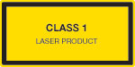 |
| 1M | Class 1M lasers are safe except when used in conjunction with optical components such as telescopes and microscopes. Lasers belonging to this class emit large-diameter or divergent beams, and the MPE cannot normally be exceeded unless focusing or imaging optics are used to narrow the beam. However, if the beam is refocused, the hazard may be increased and the class may be changed accordingly. | 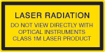 |
| 2 | Class 2 lasers, which are limited to 1 mW of visible continuous-wave radiation, are safe because the blink reflex will limit the exposure in the eye to 0.25 seconds. This category only applies to visible radiation (400 - 700 nm). | 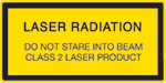 |
| 2M | Because of the blink reflex, this class of laser is classified as safe as long as the beam is not viewed through optical instruments. This laser class also applies to larger-diameter or diverging laser beams. | 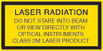 |
| 3R | Class 3R lasers produce visible and invisible light that is hazardous under direct and specular-reflection viewing conditions. Eye injuries may occur if you directly view the beam, especially when using optical instruments. Lasers in this class are considered safe as long as they are handled with restricted beam viewing. The MPE can be exceeded with this class of laser; however, this presents a low risk level to injury. Visible, continuous-wave lasers in this class are limited to 5 mW of output power. | 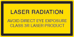 |
| 3B | Class 3B lasers are hazardous to the eye if exposed directly. Diffuse reflections are usually not harmful, but may be when using higher-power Class 3B lasers. Safe handling of devices in this class includes wearing protective eyewear where direct viewing of the laser beam may occur. Lasers of this class must be equipped with a key switch and a safety interlock; moreover, laser safety signs should be used, such that the laser cannot be used without the safety light turning on. Laser products with power output near the upper range of Class 3B may also cause skin burns. | 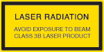 |
| 4 | This class of laser may cause damage to the skin, and also to the eye, even from the viewing of diffuse reflections. These hazards may also apply to indirect or non-specular reflections of the beam, even from apparently matte surfaces. Great care must be taken when handling these lasers. They also represent a fire risk, because they may ignite combustible material. Class 4 lasers must be equipped with a key switch and a safety interlock. |  |
| All class 2 lasers (and higher) must display, in addition to the corresponding sign above, this triangular warning sign. |  |
|
We cordially thank Antje Bergmann (Karlsruhe Institute of Technology) for sharing her design of the quantum eraser setup.
Do you have ideas for an experiment that you would like to see implemented in an educational kit? Contact us at techsupport@thorlabs.com; we'd love to hear from you.
| Posted Comments: | |
user
(posted 2020-07-13 14:51:24.007) I want to try this at home, but this is quite expensive. It’d be nice if these sorts of experiments were more accessible to people who want to observe quantum effects for themselves. I’d be willing to pay $400 at most, but $2000 is a big investment for something that might not even be what I’m looking for. MKiess
(posted 2020-07-16 03:45:38.0) This is an response from Michael of Thorlabs. Thank you very much for your inquiry. I have contacted you directly to discuss your application and your specific case in order to find a solution together. |