 Products Home / Optical Elements / Optical Filters / Neutral Density Filters / Neutral Density Filters: Absorptive/Reflective / Unmounted N-BK7 Reflective Neutral Density Filters
Unmounted N-BK7 Reflective Neutral Density Filters
- Optical Densities from 0.1 to 4.0
- N-BK7 Substrate with Inconel Coating
- Attenuation for the 350 - 1100 nm Range
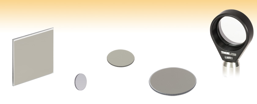
ND230B
50 mm x 50 mm
ND501B
Ø1/2"
ND10B
Ø25 mm
ND2R40B
Ø2"
ND05B Filter in an
LMR1 Lens Mount


Please Wait
| Neutral Density Filter Selection Guide |
|
|---|---|
| Absorptive | |
| Uncoated (400 - 650 nm) |
Mounted |
| Unmounted | |
| Uncoated (1000 - 2600 nm) |
Mounted |
| Unmounted | |
| AR Coated (350 - 700 nm) |
Mounted |
| Unmounted | |
| AR Coated (650 - 1050 nm) |
Mounted |
| Unmounted | |
| AR Coated (1050 - 1700 nm) |
Mounted |
| Unmounted | |
| Variable | |
| Reflective | |
| UV Fused Silica (200 - 1200 nm) |
Mounted |
| Unmounted | |
| N-BK7 (350 - 1100 nm) |
Mounted |
| Unmounted | |
| ZnSe (2 - 16 µm) |
Mounted |
| Unmounted | |
| Wedged UVFS (200 - 1200 nm) | |
| Wedged N-BK7 (350 - 1100 nm) | |
| Wedged ZnSe (2 - 16 µm) | |
| Variable | |
| Neutral Density Filter Kits | |
Features
- Ø1/2", Ø25 mm, Ø50 mm, and 50 mm Square Unmounted Filters
- Attenuates Over the 350 to 1100 nm Wavelength Range
- Optical Densities Ranging from 0.1 to 4.0
Thorlabs' Reflective Neutral Density (ND) Filters provide uniform attenuation over the broad spectral range from 350 to 1100 nm. These metallic filters have optical densities ranging from 0.1 to 4.0. The Graphs tab above contains plots of the transmission and reflection for each filter for a broad wavelength range.
These filters consist of an N-BK7 glass substrate with a metal (Inconel) coating deposited on one side. Inconel is a metallic alloy that ensures flat spectral response from the UV to the near IR. Unprotected metal coatings like this should only be cleaned by blown air, never touched, as contact may cause scratching to the unprotected surface. Although these are reflective ND filters, the Inconel coating does absorb some of the incident light, which limits the use of these filters to low-power applications. Inconel is resistant to aging under normal conditions; however, it will oxidize at elevated temperatures. To prevent oxidation, Thorlabs recommends using these ND filters at temperatures below 100 °C. To achieve the best performance, light should be incident on the side with the Inconel coating; this allows attenuation to occur before etalon effects occur within the filter's substrate.
Our Ø1/2", Ø25 mm, and Ø50 mm N-BK7 reflective ND filters are also available mounted in SM05-, SM1-, or SM2-threaded lens tubes, respectively. Thorlabs also offers UV fused silica and variable reflective ND filters, as well as a complete line of absorptive ND filters in several sizes; the Selection Guide table to the right contains links to all of the available options.
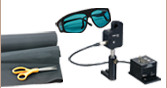
Please note that these products are not designed for use as laser safety equipment. For lab safety, Thorlabs offers an extensive line of safety and blackout products, including beam blocks, that significantly reduce exposure to stray light.
Optical Density and Transmission
Optical density (OD) indicates the attenuation factor provided by an optical filter, i.e. how much it reduces the optical power of an incident beam. OD is related to the transmission, T, by the equation
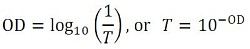
where T is a value between 0 and 1. Choosing a reflective ND filter with a higher optical density will translate to lower transmission and greater reflection of the incident light. For higher transmission and less reflection, a lower optical density would be appropriate. As an example, if a filter with an OD of 2 results in a transmission value of 0.01, this means the filter attenuates the beam to 1% of the incident power. Please note that the transmission data for our neutral density filters is provided in percent (%).
| General Specifications | ||||
|---|---|---|---|---|
| Filter | ND5xxB | NDxxB | ND2RxxB | ND2xxB |
| Substrate | N-BK7a | |||
| Size | Ø12.7 mm | Ø25.0 mm | Ø50.0 mm | 50.0 mm x 50.0 mm |
| Face Dimensional Tolerance | +0.0 / -0.2 mm | |||
| Thickness | 1.0 ± 0.1 mm | 2.0 ± 0.1 mm | ||
| Clear Aperture | >90% of Outer Diameter | >45.0 mm x 45.0 mm | ||
| Surface Accuracy/Flatnessb |
<2λ | <2λc | <2λd | |
| Surface Quality | 40-20 Scratch-Dig | |||
| Parallelism | <20 arcmin | <30 arcsec | ||
| Optical Density Tolerance | ±5.0% | |||
| Optical Density | Damage Thresholds | |
|---|---|---|
| 0.3 | CWa | 16 W/cm (532 nm, Ø0.051 mm) |
| Pulsed | 0.025 J/cm2 (532 nm, 10 ns, 10 Hz, Ø0.493 mm) | |
| 1.0 | CWa | 5 W/cm (532 nm, Ø0.019 mm) |
| Pulsed | 0.025 J/cm2 (532 nm, 10 ns, 10 Hz, Ø0.566 mm) | |
| 2.0 | CWa | 10 W/cm (532 nm, Ø0.365 mm) |
| Pulsed | 0.025 J/cm2 (532 nm, 10 ns, 10 Hz, Ø0.493 mm) | |
| For Detailed Plot Information | |
|---|---|
| |
For individual transmission and optical density plots, as well as Excel files with raw data, click on this icon in the product tables below. |
| An Excel file with transmission and reflectance data for all N-BK7 Reflective ND filters is also available. | |
| Optical Density | Transmission | Reflectance |
|---|---|---|
| OD 0.1 - 0.9 |  Click to Enlarge |
 Click to Enlarge |
| OD 1.0 - 2.0 |  Click to Enlarge |
 Click to Enlarge |
| OD 3.0 - 4.0 |  Click to Enlarge |
 Click to Enlarge |
Click to Enlarge
Water Spectrum as Recorded Through a Standard and Wedged ND filter
Comparison of Standard and Wedged ND Filters
We present laboratory measurements on the difference in the etalon effect between our standard reflective neutral density (ND) filters and our wedged reflective ND filters. In many broadband scattering or absorption measurements, it is important to understand how intensity fluctuations through the utilized optics can impact the measurement. While it is known that parallel surfaces introduce significant wavelength-dependent intensity fluctuations, we find that utilizing a wedged geometry significantly reduces these etalon effects.
For our experiment we used the SLS202 Stabilized Light Source as the broadband, fiber-coupled light source. The F260FC-C Fiber Collimator, held in the KAD11F Kinematic Pitch/Yaw Adapter, collimates the light out of the fiber. The collimated light is incident upon the ND filter that is being investigated before entering the OSA203B Optical Spectrum Analyzer. The OSA has a spectral resolution of 7.5 GHz (0.25 cm-1) and the traces were averaged (>100 scans) in order to reduce noise and allow for more accurate analysis. The data focused on a wavelength range of 1820 - 1845 nm, which covers the NIR water spectrum. Since the absorption spectrum of water is well known, it is ideal to use as a comparison to evaluate the performance difference between these two styles of ND filter.

The figure to the right summarizes the measured results for etalon effects through reflective neutral density filters. The etalon effects are quite stark, and we can see in the case of the standard ND filters that details of the water spectrum are lost to the intensity fluctuations of the background levels. By contrast, the wedged ND filters have a relatively clean signal with well-defined peaks. Data is presented for unmounted standard and wedged ND filters, though the results hold for mounted filters as well. Data is also compared to the HITRAN water spectrum standard. For details on the experimental setup employed and the results summarized here, please click here.
| Damage Threshold Specifications | ||
|---|---|---|
| Optical Density | Damage Thresholds | |
| 0.3 | CWa | 16 W/cm (532 nm, Ø0.051 mm) |
| Pulsed | 0.025 J/cm2 (532 nm, 10 ns, 10 Hz, Ø0.493 mm) | |
| 1.0 | CWa | 5 W/cm (532 nm, Ø0.019 mm) |
| Pulsed | 0.025 J/cm2 (532 nm, 10 ns, 10 Hz, Ø0.566 mm) | |
| 2.0 | CWa | 10 W/cm (532 nm, Ø0.365 mm) |
| Pulsed | 0.025 J/cm2 (532 nm, 10 ns, 10 Hz, Ø0.493 mm) | |
Damage Threshold Data for Thorlabs' Reflective ND Filters
The specifications to the right are measured data for Thorlabs' reflective neutral density filters. Damage threshold specifications are constant for a given optical density coating, regardless of the size of the filter.
Laser Induced Damage Threshold Tutorial
The following is a general overview of how laser induced damage thresholds are measured and how the values may be utilized in determining the appropriateness of an optic for a given application. When choosing optics, it is important to understand the Laser Induced Damage Threshold (LIDT) of the optics being used. The LIDT for an optic greatly depends on the type of laser you are using. Continuous wave (CW) lasers typically cause damage from thermal effects (absorption either in the coating or in the substrate). Pulsed lasers, on the other hand, often strip electrons from the lattice structure of an optic before causing thermal damage. Note that the guideline presented here assumes room temperature operation and optics in new condition (i.e., within scratch-dig spec, surface free of contamination, etc.). Because dust or other particles on the surface of an optic can cause damage at lower thresholds, we recommend keeping surfaces clean and free of debris. For more information on cleaning optics, please see our Optics Cleaning tutorial.
Testing Method
Thorlabs' LIDT testing is done in compliance with ISO/DIS 11254 and ISO 21254 specifications.
First, a low-power/energy beam is directed to the optic under test. The optic is exposed in 10 locations to this laser beam for 30 seconds (CW) or for a number of pulses (pulse repetition frequency specified). After exposure, the optic is examined by a microscope (~100X magnification) for any visible damage. The number of locations that are damaged at a particular power/energy level is recorded. Next, the power/energy is either increased or decreased and the optic is exposed at 10 new locations. This process is repeated until damage is observed. The damage threshold is then assigned to be the highest power/energy that the optic can withstand without causing damage. A histogram such as that below represents the testing of one BB1-E02 mirror.

The photograph above is a protected aluminum-coated mirror after LIDT testing. In this particular test, it handled 0.43 J/cm2 (1064 nm, 10 ns pulse, 10 Hz, Ø1.000 mm) before damage.

| Example Test Data | |||
|---|---|---|---|
| Fluence | # of Tested Locations | Locations with Damage | Locations Without Damage |
| 1.50 J/cm2 | 10 | 0 | 10 |
| 1.75 J/cm2 | 10 | 0 | 10 |
| 2.00 J/cm2 | 10 | 0 | 10 |
| 2.25 J/cm2 | 10 | 1 | 9 |
| 3.00 J/cm2 | 10 | 1 | 9 |
| 5.00 J/cm2 | 10 | 9 | 1 |
According to the test, the damage threshold of the mirror was 2.00 J/cm2 (532 nm, 10 ns pulse, 10 Hz, Ø0.803 mm). Please keep in mind that these tests are performed on clean optics, as dirt and contamination can significantly lower the damage threshold of a component. While the test results are only representative of one coating run, Thorlabs specifies damage threshold values that account for coating variances.
Continuous Wave and Long-Pulse Lasers
When an optic is damaged by a continuous wave (CW) laser, it is usually due to the melting of the surface as a result of absorbing the laser's energy or damage to the optical coating (antireflection) [1]. Pulsed lasers with pulse lengths longer than 1 µs can be treated as CW lasers for LIDT discussions.
When pulse lengths are between 1 ns and 1 µs, laser-induced damage can occur either because of absorption or a dielectric breakdown (therefore, a user must check both CW and pulsed LIDT). Absorption is either due to an intrinsic property of the optic or due to surface irregularities; thus LIDT values are only valid for optics meeting or exceeding the surface quality specifications given by a manufacturer. While many optics can handle high power CW lasers, cemented (e.g., achromatic doublets) or highly absorptive (e.g., ND filters) optics tend to have lower CW damage thresholds. These lower thresholds are due to absorption or scattering in the cement or metal coating.

LIDT in linear power density vs. pulse length and spot size. For long pulses to CW, linear power density becomes a constant with spot size. This graph was obtained from [1].

Pulsed lasers with high pulse repetition frequencies (PRF) may behave similarly to CW beams. Unfortunately, this is highly dependent on factors such as absorption and thermal diffusivity, so there is no reliable method for determining when a high PRF laser will damage an optic due to thermal effects. For beams with a high PRF both the average and peak powers must be compared to the equivalent CW power. Additionally, for highly transparent materials, there is little to no drop in the LIDT with increasing PRF.
In order to use the specified CW damage threshold of an optic, it is necessary to know the following:
- Wavelength of your laser
- Beam diameter of your beam (1/e2)
- Approximate intensity profile of your beam (e.g., Gaussian)
- Linear power density of your beam (total power divided by 1/e2 beam diameter)
Thorlabs expresses LIDT for CW lasers as a linear power density measured in W/cm. In this regime, the LIDT given as a linear power density can be applied to any beam diameter; one does not need to compute an adjusted LIDT to adjust for changes in spot size, as demonstrated by the graph to the right. Average linear power density can be calculated using the equation below.

The calculation above assumes a uniform beam intensity profile. You must now consider hotspots in the beam or other non-uniform intensity profiles and roughly calculate a maximum power density. For reference, a Gaussian beam typically has a maximum power density that is twice that of the uniform beam (see lower right).
Now compare the maximum power density to that which is specified as the LIDT for the optic. If the optic was tested at a wavelength other than your operating wavelength, the damage threshold must be scaled appropriately. A good rule of thumb is that the damage threshold has a linear relationship with wavelength such that as you move to shorter wavelengths, the damage threshold decreases (i.e., a LIDT of 10 W/cm at 1310 nm scales to 5 W/cm at 655 nm):

While this rule of thumb provides a general trend, it is not a quantitative analysis of LIDT vs wavelength. In CW applications, for instance, damage scales more strongly with absorption in the coating and substrate, which does not necessarily scale well with wavelength. While the above procedure provides a good rule of thumb for LIDT values, please contact Tech Support if your wavelength is different from the specified LIDT wavelength. If your power density is less than the adjusted LIDT of the optic, then the optic should work for your application.
Please note that we have a buffer built in between the specified damage thresholds online and the tests which we have done, which accommodates variation between batches. Upon request, we can provide individual test information and a testing certificate. The damage analysis will be carried out on a similar optic (customer's optic will not be damaged). Testing may result in additional costs or lead times. Contact Tech Support for more information.
Pulsed Lasers
As previously stated, pulsed lasers typically induce a different type of damage to the optic than CW lasers. Pulsed lasers often do not heat the optic enough to damage it; instead, pulsed lasers produce strong electric fields capable of inducing dielectric breakdown in the material. Unfortunately, it can be very difficult to compare the LIDT specification of an optic to your laser. There are multiple regimes in which a pulsed laser can damage an optic and this is based on the laser's pulse length. The highlighted columns in the table below outline the relevant pulse lengths for our specified LIDT values.
Pulses shorter than 10-9 s cannot be compared to our specified LIDT values with much reliability. In this ultra-short-pulse regime various mechanics, such as multiphoton-avalanche ionization, take over as the predominate damage mechanism [2]. In contrast, pulses between 10-7 s and 10-4 s may cause damage to an optic either because of dielectric breakdown or thermal effects. This means that both CW and pulsed damage thresholds must be compared to the laser beam to determine whether the optic is suitable for your application.
| Pulse Duration | t < 10-9 s | 10-9 < t < 10-7 s | 10-7 < t < 10-4 s | t > 10-4 s |
|---|---|---|---|---|
| Damage Mechanism | Avalanche Ionization | Dielectric Breakdown | Dielectric Breakdown or Thermal | Thermal |
| Relevant Damage Specification | No Comparison (See Above) | Pulsed | Pulsed and CW | CW |
When comparing an LIDT specified for a pulsed laser to your laser, it is essential to know the following:

LIDT in energy density vs. pulse length and spot size. For short pulses, energy density becomes a constant with spot size. This graph was obtained from [1].
- Wavelength of your laser
- Energy density of your beam (total energy divided by 1/e2 area)
- Pulse length of your laser
- Pulse repetition frequency (prf) of your laser
- Beam diameter of your laser (1/e2 )
- Approximate intensity profile of your beam (e.g., Gaussian)
The energy density of your beam should be calculated in terms of J/cm2. The graph to the right shows why expressing the LIDT as an energy density provides the best metric for short pulse sources. In this regime, the LIDT given as an energy density can be applied to any beam diameter; one does not need to compute an adjusted LIDT to adjust for changes in spot size. This calculation assumes a uniform beam intensity profile. You must now adjust this energy density to account for hotspots or other nonuniform intensity profiles and roughly calculate a maximum energy density. For reference a Gaussian beam typically has a maximum energy density that is twice that of the 1/e2 beam.
Now compare the maximum energy density to that which is specified as the LIDT for the optic. If the optic was tested at a wavelength other than your operating wavelength, the damage threshold must be scaled appropriately [3]. A good rule of thumb is that the damage threshold has an inverse square root relationship with wavelength such that as you move to shorter wavelengths, the damage threshold decreases (i.e., a LIDT of 1 J/cm2 at 1064 nm scales to 0.7 J/cm2 at 532 nm):

You now have a wavelength-adjusted energy density, which you will use in the following step.
Beam diameter is also important to know when comparing damage thresholds. While the LIDT, when expressed in units of J/cm², scales independently of spot size; large beam sizes are more likely to illuminate a larger number of defects which can lead to greater variances in the LIDT [4]. For data presented here, a <1 mm beam size was used to measure the LIDT. For beams sizes greater than 5 mm, the LIDT (J/cm2) will not scale independently of beam diameter due to the larger size beam exposing more defects.
The pulse length must now be compensated for. The longer the pulse duration, the more energy the optic can handle. For pulse widths between 1 - 100 ns, an approximation is as follows:

Use this formula to calculate the Adjusted LIDT for an optic based on your pulse length. If your maximum energy density is less than this adjusted LIDT maximum energy density, then the optic should be suitable for your application. Keep in mind that this calculation is only used for pulses between 10-9 s and 10-7 s. For pulses between 10-7 s and 10-4 s, the CW LIDT must also be checked before deeming the optic appropriate for your application.
Please note that we have a buffer built in between the specified damage thresholds online and the tests which we have done, which accommodates variation between batches. Upon request, we can provide individual test information and a testing certificate. Contact Tech Support for more information.
[1] R. M. Wood, Optics and Laser Tech. 29, 517 (1998).
[2] Roger M. Wood, Laser-Induced Damage of Optical Materials (Institute of Physics Publishing, Philadelphia, PA, 2003).
[3] C. W. Carr et al., Phys. Rev. Lett. 91, 127402 (2003).
[4] N. Bloembergen, Appl. Opt. 12, 661 (1973).

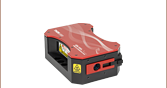
In order to illustrate the process of determining whether a given laser system will damage an optic, a number of example calculations of laser induced damage threshold are given below. For assistance with performing similar calculations, we provide a spreadsheet calculator that can be downloaded by clicking the button to the right. To use the calculator, enter the specified LIDT value of the optic under consideration and the relevant parameters of your laser system in the green boxes. The spreadsheet will then calculate a linear power density for CW and pulsed systems, as well as an energy density value for pulsed systems. These values are used to calculate adjusted, scaled LIDT values for the optics based on accepted scaling laws. This calculator assumes a Gaussian beam profile, so a correction factor must be introduced for other beam shapes (uniform, etc.). The LIDT scaling laws are determined from empirical relationships; their accuracy is not guaranteed. Remember that absorption by optics or coatings can significantly reduce LIDT in some spectral regions. These LIDT values are not valid for ultrashort pulses less than one nanosecond in duration.
A Gaussian beam profile has about twice the maximum intensity of a uniform beam profile.
CW Laser Example
Suppose that a CW laser system at 1319 nm produces a 0.5 W Gaussian beam that has a 1/e2 diameter of 10 mm. A naive calculation of the average linear power density of this beam would yield a value of 0.5 W/cm, given by the total power divided by the beam diameter:
However, the maximum power density of a Gaussian beam is about twice the maximum power density of a uniform beam, as shown in the graph to the right. Therefore, a more accurate determination of the maximum linear power density of the system is 1 W/cm.
An AC127-030-C achromatic doublet lens has a specified CW LIDT of 350 W/cm, as tested at 1550 nm. CW damage threshold values typically scale directly with the wavelength of the laser source, so this yields an adjusted LIDT value:
The adjusted LIDT value of 350 W/cm x (1319 nm / 1550 nm) = 298 W/cm is significantly higher than the calculated maximum linear power density of the laser system, so it would be safe to use this doublet lens for this application.
Pulsed Nanosecond Laser Example: Scaling for Different Pulse Durations
Suppose that a pulsed Nd:YAG laser system is frequency tripled to produce a 10 Hz output, consisting of 2 ns output pulses at 355 nm, each with 1 J of energy, in a Gaussian beam with a 1.9 cm beam diameter (1/e2). The average energy density of each pulse is found by dividing the pulse energy by the beam area:

As described above, the maximum energy density of a Gaussian beam is about twice the average energy density. So, the maximum energy density of this beam is ~0.7 J/cm2.
The energy density of the beam can be compared to the LIDT values of 1 J/cm2 and 3.5 J/cm2 for a BB1-E01 broadband dielectric mirror and an NB1-K08 Nd:YAG laser line mirror, respectively. Both of these LIDT values, while measured at 355 nm, were determined with a 10 ns pulsed laser at 10 Hz. Therefore, an adjustment must be applied for the shorter pulse duration of the system under consideration. As described on the previous tab, LIDT values in the nanosecond pulse regime scale with the square root of the laser pulse duration:
This adjustment factor results in LIDT values of 0.45 J/cm2 for the BB1-E01 broadband mirror and 1.6 J/cm2 for the Nd:YAG laser line mirror, which are to be compared with the 0.7 J/cm2 maximum energy density of the beam. While the broadband mirror would likely be damaged by the laser, the more specialized laser line mirror is appropriate for use with this system.
Pulsed Nanosecond Laser Example: Scaling for Different Wavelengths
Suppose that a pulsed laser system emits 10 ns pulses at 2.5 Hz, each with 100 mJ of energy at 1064 nm in a 16 mm diameter beam (1/e2) that must be attenuated with a neutral density filter. For a Gaussian output, these specifications result in a maximum energy density of 0.1 J/cm2. The damage threshold of an NDUV10A Ø25 mm, OD 1.0, reflective neutral density filter is 0.05 J/cm2 for 10 ns pulses at 355 nm, while the damage threshold of the similar NE10A absorptive filter is 10 J/cm2 for 10 ns pulses at 532 nm. As described on the previous tab, the LIDT value of an optic scales with the square root of the wavelength in the nanosecond pulse regime:
This scaling gives adjusted LIDT values of 0.08 J/cm2 for the reflective filter and 14 J/cm2 for the absorptive filter. In this case, the absorptive filter is the best choice in order to avoid optical damage.
Pulsed Microsecond Laser Example
Consider a laser system that produces 1 µs pulses, each containing 150 µJ of energy at a repetition rate of 50 kHz, resulting in a relatively high duty cycle of 5%. This system falls somewhere between the regimes of CW and pulsed laser induced damage, and could potentially damage an optic by mechanisms associated with either regime. As a result, both CW and pulsed LIDT values must be compared to the properties of the laser system to ensure safe operation.
If this relatively long-pulse laser emits a Gaussian 12.7 mm diameter beam (1/e2) at 980 nm, then the resulting output has a linear power density of 5.9 W/cm and an energy density of 1.2 x 10⁻⁴ J/cm2 per pulse. This can be compared to the LIDT values for a WPQ10E-980 polymer zero-order quarter-wave plate, which are 5 W/cm for CW radiation at 810 nm and 5 J/cm2 for a 10 ns pulse at 810 nm. As before, the CW LIDT of the optic scales linearly with the laser wavelength, resulting in an adjusted CW value of 6 W/cm at 980 nm. On the other hand, the pulsed LIDT scales with the square root of the laser wavelength and the square root of the pulse duration, resulting in an adjusted value of 55 J/cm2 for a 1 µs pulse at 980 nm. The pulsed LIDT of the optic is significantly greater than the energy density of the laser pulse, so individual pulses will not damage the wave plate. However, the large average linear power density of the laser system may cause thermal damage to the optic, much like a high-power CW beam.
| Posted Comments: | |
user
(posted 2022-09-11 21:39:05.827) Hello,
I've noted that the graphs don't specify the transmission for OD 3.0 and & 4.0 above 1000nm. Are these unsuitable for 1060nm? ppestre
(posted 2022-09-15 12:23:02.0) Thank you for your feedback! Yes, the operating range for attenuation goes up to 1100 nm. We have updated the graph accordingly. 曾 毛毛
(posted 2020-08-03 16:51:17.67) 请问吸收型和反射型中性密度衰减片是否适合在温度150度场景下使用? YLohia
(posted 2020-08-03 11:23:03.0) Thank you for contacting Thorlabs. An Applications Engineer from our team in China will reach out to you directly. Hugo Feyrit
(posted 2020-05-29 10:54:22.723) Hi,
For my application, I need to know the refractive index (let say at around 500 nm) of the reflective optical density ND520B (not the one of the N-BK7 substrate).
Could you please provide this information?
Thanks YLohia
(posted 2020-07-14 02:10:46.0) Hello, thank you for contacting Thorlabs. The reflective material in these filters is Inconel and the index of refraction values for this can be found online. I had reached out to you directly with more information at the time of your original posting. s.sobika
(posted 2018-03-15 08:31:17.77) Hi, I have an ND530B filter and I would like to know if this filter preserve the polarization effect ? llamb
(posted 2018-03-19 10:20:17.0) Hello, thank you for contacting Thorlabs. While we do not have any specific polarization test data on this, the metal Inconel coating will likely introduce some polarization effects on your incident beam. It's not designed to be polarization-maintaining, so a small change in polarization is to be expected. markus.augustin
(posted 2017-09-05 07:59:52.853) Hi, I'm also interested in the tolerance of the ND05b and ND20b (or ND505b and ND520b). Can you please provide typical variation on the OD over range 400 - 1000 nm?
Markus tfrisch
(posted 2017-09-15 11:23:30.0) Hello, thank you for contacting Thorlabs. The tolerance for OD is ±5% at the design wavelength of 633nm. I will reach out to you about typical data, but unfortunately, we do not have any statistical analysis on historical variations. We are able to offer individualized testing at other wavelengths, however. cpepe
(posted 2017-03-06 09:17:17.513) Hi,
I have an ND10B filter which I can see is a bit dirty. I read that you recommend only to clean it with air but this didnt work. I therefore wanted to hear if you have any other recomendations or will eg methanol just make it worse? tfrisch
(posted 2017-03-13 05:06:43.0) Hello, thank you for contacting Thorlabs. Unfortunately, I would not recommend cleaning with any solvents as unprotected coatings are easily damaged by contact. I will reach out to you directly. david.chadwick
(posted 2016-11-30 14:08:53.617) I'm sure it's in there somewhere -
Is there a maximum / minimum tolerance for the ND 3.0 value across the spectral band ?
Thanks,
Dave tfrisch
(posted 2016-12-05 09:37:34.0) Hi Dave, thank you for contacting Thorlabs. The tolerance we use for inspection is ±5% of the OD at the design wavelength (633nm in this case). I will contact you directly with typical data on the OD over the operating range. pmartel
(posted 2015-04-14 08:02:20.793) just purchased ND10B and similar filters.
is there a particular face of the filter the laser should strike, or wors good either way?
thanks for your input besembeson
(posted 2015-04-21 06:08:04.0) Response from Bweh at Thorlabs. The laser input should be to the face with the metal (inconel) coating. user
(posted 2013-10-29 16:33:50.13) Do you have data for the transmission for s- and p-polarized light? tcohen
(posted 2013-10-29 13:14:00.0) Response from Tim at Thorlabs: Thanks for your comment. These were measured at 0deg AOI for transmission, but if you’d like to see S&P data with some angle of incidence, we can provide further data. I don’t see that you left any contact info, so please let us know if you’d like to go over this further at Techsupport@thorlabs.com. info
(posted 2013-08-05 13:25:29.13) Welche absolute Genauigkeit hat der Filter ND20B bei 850 nm? Aus dem Diagramm läßt sich 1,1% ablesen, aber wie gut stimmen diese?
Kunden NR 346016 jlow
(posted 2013-08-07 15:04:00.0) Response from Jeremy at Thorlabs: The data on the graph is typical at that range and should be used as a guideline value. We could provide the filter specifically tested at 850nm if needed. We will get in contact with you to discuss about this. tcohen
(posted 2013-02-21 14:55:00.0) Response from Tim at Thorlabs to Ryan: Thank you for contacting us. We have reflectivity data past 1100nm on the “Graphs” tab and I will contact you directly to provide typical plots on %T extended past 1100nm. tcohen
(posted 2012-05-22 11:55:00.0) Response from Tim at Thorlabs: Thank you for your interest in our Reflective ND Filters. We are able to quote many custom optics and I will contact you directly to get more information so that we may provide pricing and lead time. yu.zhang
(posted 2012-05-21 02:34:51.0) N-BK7 Reflective Neutral Density Filters
We are interested in this product. But we need the size to be 180 mm x 180 mm.
Can thorlab customize for us? What will be the piece price (10 pieces for example)?
Thanks! |

 Zoom
ZoomClick on ![]() for a plot and downloadable data. The black dashed line in each plot indicates the designated optical density at 633 nm. See the Specs tab above for optical density tolerance.
for a plot and downloadable data. The black dashed line in each plot indicates the designated optical density at 633 nm. See the Specs tab above for optical density tolerance.
| Item # | Optical Densitya (Transmission) |
Transmission Data |
|---|---|---|
| ND501B | 0.1 (79%) | |
| ND502B | 0.2 (63%) | |
| ND503B | 0.3 (50%) | |
| ND504B | 0.4 (40%) | |
| ND505B | 0.5 (32%) | |
| ND506B | 0.6 (25%) | |
| ND507B | 0.7 (20%) | |
| ND508B | 0.8 (16%) |
| Item # | Optical Densitya (Transmission) |
Transmission Data |
|---|---|---|
| ND509B | 0.9 (13%) | |
| ND510B | 1.0 (10%) | |
| ND513B | 1.3 (5%) | |
| ND515B | 1.5 (3%) | |
| ND520B | 2.0 (1%) | |
| ND530B | 3.0 (0.1%) | |
| ND540B | 4.0 (0.01%) |

 Zoom
ZoomClick on ![]() for a plot and downloadable data. The black dashed line in each plot indicates the designated optical density at 633 nm. See the Specs tab above for optical density tolerance.
for a plot and downloadable data. The black dashed line in each plot indicates the designated optical density at 633 nm. See the Specs tab above for optical density tolerance.
| Item # | Optical Densitya (Transmission) |
Transmission Data |
|---|---|---|
| ND01B | 0.1 (79%) | |
| ND02B | 0.2 (63%) | |
| ND03B | 0.3 (50%) | |
| ND04B | 0.4 (40%) | |
| ND05B | 0.5 (32%) | |
| ND06B | 0.6 (25%) | |
| ND07B | 0.7 (20%) | |
| ND08B | 0.8 (16%) |
| Item # | Optical Densitya (Transmission) |
Transmission Data |
|---|---|---|
| ND09B | 0.9 (13%) | |
| ND10B | 1.0 (10%) | |
| ND13B | 1.3 (5%) | |
| ND15B | 1.5 (3%) | |
| ND20B | 2.0 (1%) | |
| ND30B | 3.0 (0.1%) | |
| ND40B | 4.0 (0.01%) |

 Zoom
ZoomClick on ![]() for a plot and downloadable data. The black dashed line in each plot indicates the designated optical density at 633 nm. See the Specs tab above for optical density tolerance.
for a plot and downloadable data. The black dashed line in each plot indicates the designated optical density at 633 nm. See the Specs tab above for optical density tolerance.
| Item # | Optical Densitya (Transmission) |
Transmission Data |
|---|---|---|
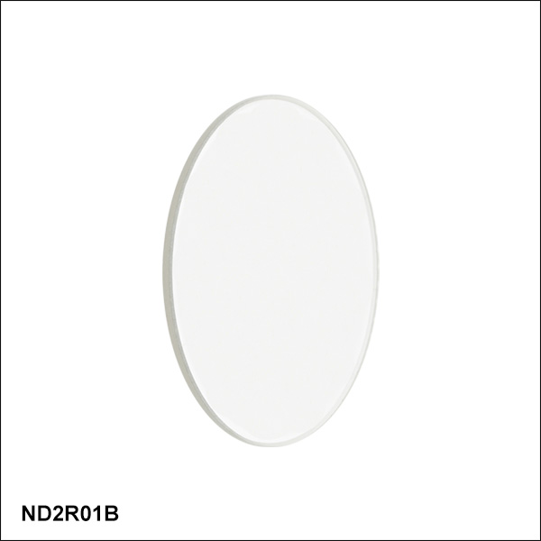
| ND2R01B | 0.1 (79%) | |
| ND2R02B | 0.2 (63%) | |
| ND2R03B | 0.3 (50%) | |
| ND2R04B | 0.4 (40%) | |
| ND2R05B | 0.5 (32%) | |
| ND2R06B | 0.6 (25%) | |
| ND2R07B | 0.7 (20%) | |
| ND2R08B | 0.8 (16%) |
| Item # | Optical Densitya (Transmission) |
Transmission Data |
|---|---|---|
| ND2R09B | 0.9 (13%) | |
| ND2R10B | 1.0 (10%) | |
| ND2R13B | 1.3 (5%) | |
| ND2R15B | 1.5 (3%) | |
| ND2R20B | 2.0 (1%) | |
| ND2R30B | 3.0 (0.1%) | |
| ND2R40B | 4.0 (0.01%) |

 Zoom
ZoomClick on ![]() for a plot and downloadable data. The black dashed line in each plot indicates the designated optical density at 633 nm. See the Specs tab above for optical density tolerance.
for a plot and downloadable data. The black dashed line in each plot indicates the designated optical density at 633 nm. See the Specs tab above for optical density tolerance.
| Item # | Optical Densitya (Transmission) |
Transmission Data |
|---|---|---|
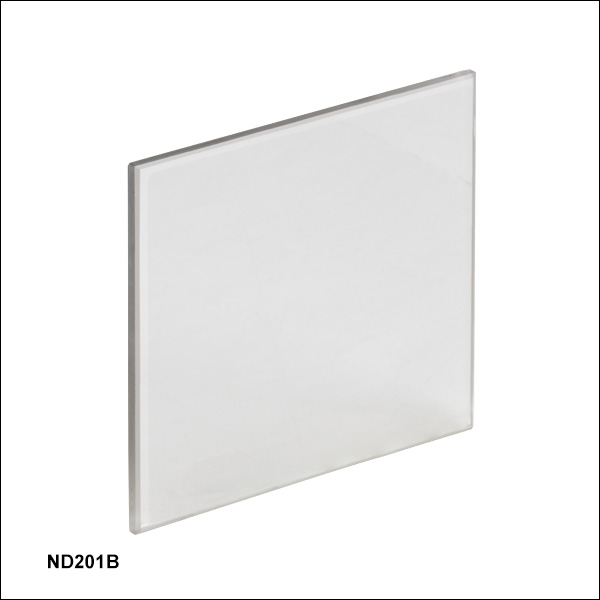
| ND201B | 0.1 (79%) | |
| ND202B | 0.2 (63%) | |
| ND203B | 0.3 (50%) | |
| ND204B | 0.4 (40%) | |
| ND205B | 0.5 (32%) | |
| ND206B | 0.6 (25%) | |
| ND207B | 0.7 (20%) | |
| ND208B | 0.8 (16%) |
| Item # | Optical Densitya (Transmission) |
Transmission Data |
|---|---|---|
| ND209B | 0.9 (13%) | |
| ND210B | 1.0 (10%) | |
| ND213B | 1.3 (5%) | |
| ND215B | 1.5 (3%) | |
| ND220B | 2.0 (1%) | |
| ND230B | 3.0 (0.1%) | |
| ND240B | 4.0 (0.01%) |