 Products Home / Drivers & Mounts / Optoelectronics Mounts / TO Can Laser Diode Mounts / ESD Protection and Strain Relief Cables
ESD Protection and Strain Relief Cables
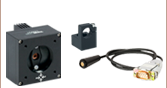
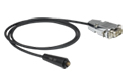
- Laser Socket and 3 Feet (0.91 Meters) of Shielded Cable
- Threads into Our Laser Diode Collimation Mounts
- Includes Clamping and Reverse Protection Diodes to Suppress ESD
- Cables Support Forward Voltages up to 3.3 V or 7.5 V
SR9B-DB9
Pin Codes: B and H
DB9 Terminated
SR9A
Pin Codes: A and E
Bare Wire Termination
SR9 Cables are
Compatible with
Our Laser Diode
Collimation Mounts


Please Wait
| Item # Prefixa |
Supported Pin Style |
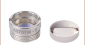
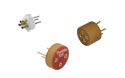
Component Socket |
Max LD Forward Voltage |
|---|---|---|---|
| SR9A | A and E | S8060 | 3.3 V |
| SR9B | B and H | S8060 | |
| SR9C | C and H | S8060 | |
| SR9D | D | S8060-4 | |
| SR9F | F and G | S8060-4 | |
| SR9HA | A and E | S8060 | 7.5 V |
| SR9HB | B and H | S8060 | |
| SR9HF | F and G | S8060-4 |
| Diode Compatibility with Strain Relief Cables | ||
|---|---|---|
| Laser Diodes | Ø3.8 mm | x |
| Ø5.6 mm | o | |
| Ø9.0 mm | ||
| TO Can Packages | TO-5 | x |
| TO-18 | o | |
| TO-46 | o | |
 Fully Compatible
o Not a Perfect Fit, but Functional
x Not Compatible
Featureso
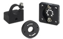
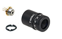
- Designed for Use with Either Ø5.6 mm or Ø9 mm Laser Diodes
- Includes Laser Socket and 3 Feet (0.91 Meters) of Shielded Cable
- External 13/32"-40 Threads Compatible with Select Laser Diode Accessories:
- Includes Clamping and Reverse Protection Diodes to Suppress ESD
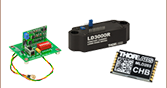
- Available with DB9 Connector for Mating Directly with LDC200C Series Laser Controllers
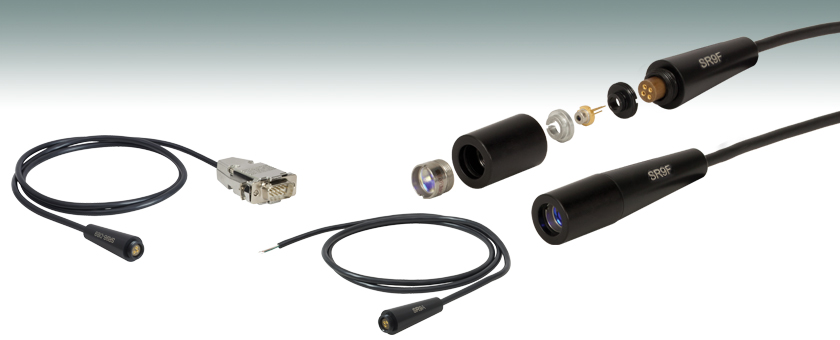
These strain relief and ESD protection products offer a convenient means of connecting a Ø5.6 mm or Ø9 mm laser diode to many of Thorlabs' laser diode controllers. Each model comes with a laser socket mounted to a small printed circuit board (PCB). The PCB contains a Schottky diode to clamp any reverse voltages that might appear across the laser diode, as well as a Zener diode to shunt any excessive voltages or ESD away from the diode.
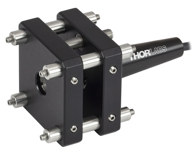
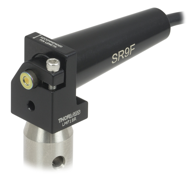
Each model corresponds to one or more of the standard Pin Styles for laser diodes (see Figure 1.3) and is compatible with our Laser Diode Collimation and Focusing Tubes, Ø1/2" Post Mounts, and Cage Plate Mounts. SR9 models are designed for laser diodes with forward voltages up to 3.3 V, while SR9H models are designed for laser diodes with forward voltages up to 7.5 V. Each strain relief is available with or without a DB9 connector. Models with item #'s that end in -DB9 are pin compatible with many of our Laser Diode Controllers (see the strain relief cable and controller pin diagrams to determine compatibility), as well as with the MLDEVAL Evaluation Board for our OEM laser diode controllers. To connect fiber-pigtailed TO can laser diodes to a breadboard or Ø1/2" post, see our L-bracket Passive Fiber-Pigtailed Laser Diode Mount.
Note: These cables are not designed to provide any temperature regulation. More information on temperature regulating a laser diode is provided in the Laser Diode Tutorial.
Figure 1.3 Supported Pin Codes
| Laser Diode Accessory Selection Guide | |||||
|---|---|---|---|---|---|
| Temperature Controlled Mounts |
Passive Mounts | Passive Mounts with Collimation Package |
Strain Relief Cables | Diode Sockets | Controllers |
 |
 |
 |
 |
 |
 |
Strain Relief Cable DB9 Connector Pin Configurations
D-type Male
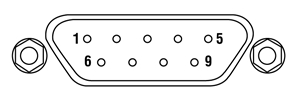
The following pin configurations are provided for strain relief cables that use a DB9 connector (Item #'s ending in -DB9) when used with the compatible style of laser diode. Each relief cable with bare wire leads has the same wire-color-to-laser-diode-pin configuration as its DB9-terminated counterpart.
| Pin Configuration for SR9A-DB9, SR9D-DB9, SR9F-DB9, SR9HA-DB9, and SR9HF-DB9 |
||
|---|---|---|
| Pin | Wire Color | Connection |
| 1 | - | Connected to Pin 5a |
| 2 | White | Photodiode Cathode (PDK) / Laser Diode Anode (LDA) |
| 3 | ||
| 4 | Red | Photodiode Anode (PDA) |
| 5 | - | Connected to Pin 1a |
| 6 | - | - |
| 7 | Green | Laser Diode Cathode (LDK) |
| 8 | - | - |
| 9 | - | - |
| Pin Configuration for SR9B-DB9 and SR9HB-DB9 | ||
|---|---|---|
| Pin | Wire Color | Connection |
| 1 | - | Connected to Pin 5a |
| 2 | White | Photodiode Cathode (PDK) / Laser Diode Cathode (LDK) |
| 3 | ||
| 4 | Red | Photodiode Anode (PDA) |
| 5 | - | Connected to Pin 1a |
| 6 | - | - |
| 7 | - | - |
| 8 | Green | Laser Diode Anode (LDA) |
| 9 | - | - |
| Pin Configuration for SR9C-DB9 | ||
|---|---|---|
| Pin | Wire Color | Connection |
| 1 | - | Connected to Pin 5a |
| 2 | Red | Photodiode Cathode (PDK) |
| 3 | White | Photodiode Anode (PDA) / Laser Diode Cathode (LDK) |
| 4 | ||
| 5 | - | Connected to Pin 1a |
| 6 | - | - |
| 7 | - | - |
| 8 | Green | Laser Diode Anode (LDA) |
| 9 | - | - |
| Posted Comments: | |
Val Capone
(posted 2024-02-10 18:04:15.597) Hi,
I've purchased an SR9B-DB9 and it is not compatible with the LPS-830-FC, which uses a Pin code "C".
Would it be ok to rewire the DB9 connector for the C code type?
Thank you. jpolaris
(posted 2024-02-22 04:31:24.0) Thank you for contacting Thorlabs. Since SR9B-DB9 and SR9C-DB9 use the same voltage protection elements, it might be possible to rewire the DB9 connector to the correct PD polarity, but there is a high risk of damaging the cable and doing so would void any warranty. The protection electronics are not designed to be easily modified. I have reached out to you directly to discuss possible alternative solutions. Patrick Kühl
(posted 2022-03-02 11:05:03.443) Hello,
we have just ordered the cable selected above (SR9A-DB9). Could you send us a matching CAD model of the side with the strain relief? When assembled is perfectly fine, it's all about the outer dimensions. That would be great!
Thank you very much and best regards,
Patrick Kühl ksosnowski
(posted 2022-03-08 12:58:55.0) Thanks for reaching out to Thorlabs. You can view the CAD file for the SR9A-DB9 by clicking on the red document icon next to the item above. Please let us know if there are any dimensions not listed which impact your application, and we can investigate further. Sangyoun Gee
(posted 2020-01-13 12:24:30.92) Hi,
Can I have a circuit diagram of SR9F?
I am considering using SR9F to mount a photo diode instead of LD. The reverse bias to PD may interfere with the Schottky diode.
Please provide me an advice.
Thanks asundararaj
(posted 2020-01-22 10:20:49.0) Thank you for contacting Thorlabs. The SR9F or other strain relief cables can be used to mount photodiodes, you would have to connect the Anode and Cathode of the photodiode on to the PDA and PDK on the Strain relief cable. The Schottky diode is across the LDA and LDK pins only and should have no effect. Warren Massey
(posted 2019-10-31 09:28:54.99) For the 3.3 V Zener diode and the Schottky diode used on the SR9F board, can you tell me what their part numbers are? Or if that is not allowed will you at least tell me what each of their respective datasheets list as their maximum-allowed operating and storage temperatures. asundararaj
(posted 2019-11-01 11:13:35.0) Thank you for contacting Thorlabs. The storage and operating temperature range of the component Zener diode is -65 to +150 °C and that for the component Schottky diode is -55 to +150 °C. Please note that this is not the storage and operating temperature of the strain relief cables. Marcelo Soto-Thompson
(posted 2019-07-12 05:19:28.637) Hello,
I seem to have broken my laser diode cable.
I ordered a new one but the the ETA is July 23rd. :-(
Is it possible to get the circuit diagram for the SR9HA-DB9 so I can troubleshoot and maybe repair it myself?
BR
Marcelo YLohia
(posted 2019-07-12 09:54:20.0) Hello Marcelo, thank you for contacting Thorlabs. I have reached out to you directly to discuss the possibility of obtaining this. vh257
(posted 2017-11-06 09:52:11.433) It seems like there is an error in the documentation (the engineering drawings/schematics) for a substantial number of the -DB9 variants of these cables. The pin-out table in the top left lists the wrong colour wires for the laser anode and laser cathode. On the SR9HB-DB9 it reads "White - Photodiode Cathode (PDK) Laser Diode Anode (LDA" and "Green - Laser Diode Cathode (LDK)". These should be the other way around, when compared to the diode pins and physically following the connections through on the circuit board. nbayconich
(posted 2017-11-20 09:42:10.0) Thank you for you feedback. We are currently correcting the pin-outs in our strain relief cable schematics. Thank you for bringing this to our attention. whath90
(posted 2016-11-15 14:16:05.94) Could you let me know the maximum allowable current of SR9B-DB9 series or what the AWG number of wire is? tfrisch
(posted 2016-11-28 02:50:56.0) Hello, thank you for contacting Thorlabs. The current will most often be limited by the diode rather than mount. The socket and AWG of the wires in the mount would be able to handle at least 1A, but since there is no temperature control for the diode in these mounts, the thermal load of a diode with such high drive current would prohibit it from being used with these cables for its own stability and temperature requirements. I have contacted you directly with more information. user
(posted 2016-02-03 10:26:56.363) Can you customize the series for PL450B? besembeson
(posted 2016-02-04 10:40:24.0) Response from Bweh at Thorlabs USA: We have the SR9HF or the SR9HF-DB9 with 7.5V forward voltage that should be suitable for the PL450B. hongsoo88
(posted 2015-08-10 13:40:07.357) Our lab already ordered MMF coupler FCMH2-FCL. and I'm thinkging of buying LP520-MF100 to connect to this coupler use LP520-MF100 as a laser source.
To use this LP520-MF100 can I use (1)SR9HF-DB9 and (2) PTLB1 ? besembeson
(posted 2015-09-24 06:35:51.0) Response from Bweh at Thorlabs USA: Yes that combination should work, if the laser diode will not be run continuously for long hours, in which case a temperature controlled mount such as the LDM9LP will be recommended. You will also need a laser current controller such as the LDC205C. ludoangot
(posted 2015-07-02 09:16:18.49) In response to my own inquiry, this can help other customers: I have just found out that the external thread on the SR9x series of cable fits the following adapter: S05LEDM and S1LEDM. Thorlabs, could you then offer the S05LEDM and S1LEDM without the LED mounting accessories (for a cheaper price), as part of your standard line of adapters? ludoangot
(posted 2015-06-03 15:07:05.723) Could you offer an adapter to mount the SR9 cable to SM1 tubes (internal = thread of the SR9 and external SM1 threads)? This would allow a great flexibility in building custom optical designs integrating the advantages of that cable (ESD protection, strain relief). jlow
(posted 2015-08-25 11:49:23.0) Response from Jeremy at Thorlabs: We offer this adapter at http://www.thorlabs.com/newgrouppage9.cfm?objectgroup_id=366. For Ø9mm LD, the part number is S1PLDM9. For Ø5.6mm LD, the part number is S1PLM56. lin.borowski
(posted 2013-08-21 11:10:19.773) Liebes Thorlabs Team,
für Beleuchtungszwecke verwenden wir eine LED mit der Halterung SM05 LED Mount for TO-18, 46...
Um Lötarbeit zu sparen würden wir diese gerne mit dem SR9A Kabel kombinieren. Damit man das Kabel aber sicher auf dem SM05 LED-Mount aufschauben kann, müßte diese einige mm länger sein.
Gibt es ein entsprechendes Bauteil, bzw. Adapter?
Oder ein Adapter um ein simples T 1-3/4 Package bzw. TO-46 Package in einer LT110P-B Collimation Tube zu verwenden?
Vielen Dank, mit freundlichen Grüßen
Lin Robert Borowski jlow
(posted 2013-09-17 16:54:00.0) Response from Jeremy at Thorlabs: Thank you for contacting Thorlabs. We will contact you directly on putting together the SR9A cable with the S05LEDM for your application. |