 Products Home / Optomechanical Components / Optical Post Assemblies / Bases / Table Clamps / Kinematic Bases
Kinematic Bases
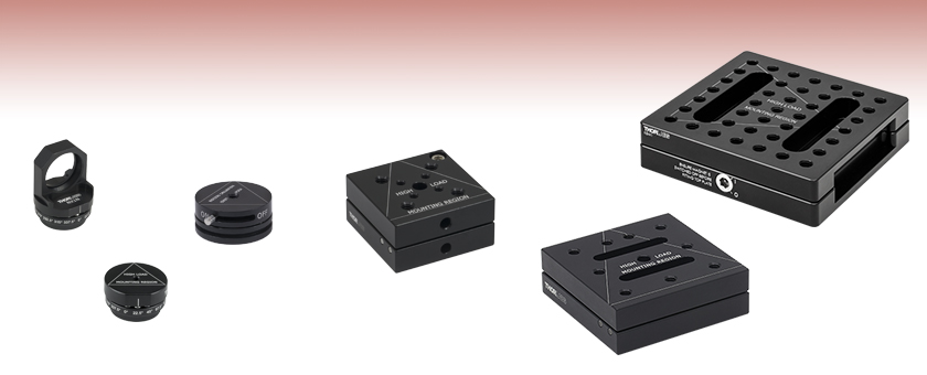
- Square and Circular Magnetic Retention Bases
- Magnetic Mounting Seats for Aluminum Breadboards
- Indexing Mounts with 22.5° Increments
- Precision Ball and V-Groove Design for High Repeatability
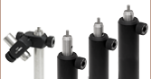
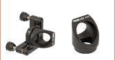
NX1N
Indexing Base
with Ø1" Optic Mount,
16 Positions
NX1NF
Indexing Base,
16 Positions
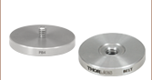
SB1
Locking Circular Base
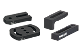
KB3X3
Magnetic Base,
3" x 3"
KBM1
Lockable Kinematic Breadboard,
3.94" x 3.94"
KB2X2
Magnetic Base,
2" x 2"


Please Wait

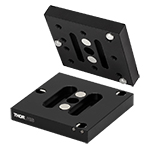
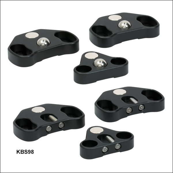
Click to Enlarge Figure 1.1 KBS98 Kinematic Seats Can Be Used to Convert a Breadboard into a Kinematic Platform
Features
- Insert and Remove Components with High Repeatability
- Ball and V-Groove Design for Precise Alignment
- Rare Earth Magnets Couple Top and Bottom Base Plates
- Some Top and Bottom Plates Available Individually or as Complete Unit
Kinematic bases are an excellent method for mounting elements that need to be inserted and removed from the optical path with a high degree of repeatability. Our ball and V-groove design allows the top plate to be kinematically positioned on the base plate with a high degree of precision. The two plates of the kinematic base are held together using pairs of rare-earth magnets.
Selection Guide
| Product Image (Click to Enlarge) |
 |
 |
 |
 |
 |
 |
 |
 |
| Item # | KB1X1 (KB25/M) |
KB2X2 (KB50/M) |
KB3X3 (KB75/M) |
KBM1 (KBM1/M) |
KBS98 | SB1 (SB1/M) |
NX1NF (NX1NF/M) | NX1N (NX1N/M) |
| Features | Compact | Multiple Mounting Options | Multiple Mounting Options | Multiple Mounting Options, Locking Magnet |
Breadboard Mounting | Locking Magnet | 16 Positions | Ø1" Optic Mount, 16 Positions |
| Tapped Holes | None | Four 1/4"-20 (M6) Taps Four 8-32 (M4) Taps |
Nine 1/4"-20 (M6) Taps | 39 1/4"-20 (M6) Taps | N/A | 1/4"-20 (M6) Tap | 8-32 (M4) Tap | N/A |
| Counterbores | #8 (M4) Hole | 1/4" (M6) Hole | 1/4" (M6) Hole | None | 12 1/4" (M6) Slots | None | None | N/A |
| Size | 1" x 1" (25 mm x 25 mm) |
2" x 2" (50 mm x 50 mm) |
3" x 3" (75 mm x 75 mm) |
3.94" x 3.94" (100 mm x 100 mm) |
N/A | Ø1.7" (Ø43 mm) | Ø1.3" (Ø33 mm) | Ø1.3" (Ø33 mm) |
Repeatability Testing
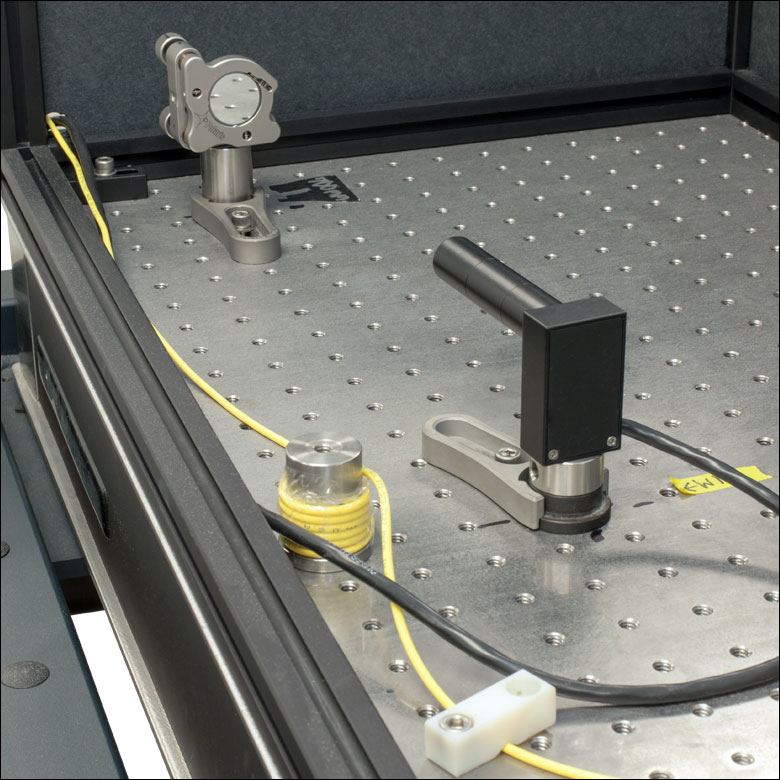
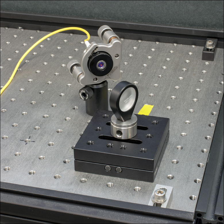
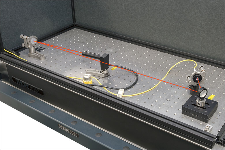
A selection of Thorlabs Kinematic Bases were tested to determine the deviation of a reflected beam attributed to removing and replacing the top plate of the base. The test setup (see Figure 2.1) consisted of an S1FC635 fiber-coupled laser source terminating in a fiber collimator that was held in a previous-generation Polaris® Mirror Mount. The collimated beam was directed towards a BB1-E02 mirror housed in an LMR1 fixed mount that was post mounted on the kinematic base being tested (see Figure 2.2). After reflecting off the first mirror, the beam traveled towards and reflected off of a second mirror housed in a previous-generation Polaris mount. After reflection, the light was directed onto a PDP90A Lateral Effect Position Sensor that had three SM05L10 SM05-Threaded Lens Tubes attached to the front to block stray light (see Figure 2.3). The total beam path is shown in Figure 2.1 and was 1 m long.
Click to Enlarge
Figure 2.3 BB1-E02 Mirror in Previous-Generation Polaris Mount and PDP90A Position Sensor with SM05L10 Lens Tubes
Click to Enlarge
Figure 2.2 S1FC635 Fiber-Coupled Laser Directed Towards a BB1-E02 Mirror Mounted on Top of the Kinematic Base Being Tested
Click to Enlarge
Figure 2.1 Experimental Apparatus for Repeatability Testing with
1 m Beam Path
The test was conducted by first centering the beam on the sensor through adjustment of the Polaris mount holding the second mirror. After centering the beam, thirty seconds were allowed to pass for stabilization purposes, and then a measurement of the beam position was made and recorded as the inital position. Next, the top plate of the kinematic base was lifted from the bottom and then replaced in the same orientation. After a thirty second stabilization period, a second measurement of the beam position was taken. Finally, the Polaris mirror mount was readjusted to center the beam on the sensor, and the process was repeated. Sixty data points were collected, amounting to thirty measurements of the beam displacement.
The results of the measurements are presented in Tables 2.4 through 2.8 as the absolute difference in µrad between the original position of the beam on the sensor and the position after removing and replacing the top plate of the kinematic base. Each value has been divided by two because a change of θ in the mirror's angle results in a change of 2θ in the measured position. The combined value takes into account both X- and Y-position measurements and represents the net distance of the deviation from the origin.
| Table 2.4 KB1X1 (KB25/M) - Summary of Results | |||||
|---|---|---|---|---|---|
| Dimension | Mean | Median | Minimum | Maximum | Plot |
| |ΔX| | 2.40 µrad | 1.20 µrad | 0.03 µrad | 26.72 µrad |  |
| |ΔY| | 4.78 µrad | 2.04 µrad | 0.04 µrad | 21.71 µrad |  |
| Combined | 6.36 µrad | 2.95 µrad | 0.58 µrad | 26.72 µrad |  |
| Table 2.5 KB2X2 (KB50/M) - Summary of Results | |||||
|---|---|---|---|---|---|
| Dimension | Mean | Median | Minimum | Maximum | Plot |
| |ΔX| | 10.22 µrad | 10.39 µrad | 0.95 µrad | 19.37 µrad |  |
| |ΔY| | 6.04 µrad | 5.76 µrad | 0 µrad | 24.16 µrad |  |
| Combined | 11.87 µrad | 11.43 µrad | 3.60 µrad | 30.96 µrad |  |
| Table 2.6 KB3X3 (KB75/M) - Summary of Results | |||||
|---|---|---|---|---|---|
| Dimension | Mean | Median | Minimum | Maximum | Plot |
| |ΔX| | 16.71 µrad | 8.00 µrad | 0.06 µrad | 73.54 µrad |  |
| |ΔY| | 10.47 µrad | 3.04 µrad | 0.26 µrad | 58.63 µrad |  |
| Combined | 21.20 µrad | 11.74 µrad | 1.30 µrad | 81.90 µrad |  |
| Table 2.7 SB1 (SB1/M) - Summary of Results | |||||
|---|---|---|---|---|---|
| Dimension | Mean | Median | Minimum | Maximum | Plot |
| |ΔX| | 9.15 µrad | 0.64 µrad | 0.01 µrad | 159.40 µrad |  |
| |ΔY| | 3.07 µrad | 1.71 µrad | 0.01 µrad | 17.48 µrad |  |
| Combined | 11.21 µrad | 2.31 µrad | 0.52 µrad | 159.47 µrad |  |
| Table 2.8 NX1NF (NX1NF/M) and NX1N (NX1N/M) - Summary of Results | |||||
|---|---|---|---|---|---|
| Dimension | Mean | Median | Minimum | Maximum | Plot |
| |ΔX| | 10.05 µrad | 1.32 µrad | 0.09 µrad | 140.45 µrad |  |
| |ΔY| | 1.30 µrad | 1.00 µrad | 0.01 µrad | 4.27 µrad |  |
| Combined | 10.6 µrad | 2.12 µrad | 0.38 µrad | 140.50 µrad |  |
| Posted Comments: | |
Petr Zimmermann
(posted 2025-01-31 12:26:16.29) We would like to use this in a high vacuum application. For that we have strict requirements on the outgassing, therefore Id like to ask: How are the magnets held inside: do u use any kind of glue or are they press fitted somehow? Thanks a lot, Petr Liam Connolly
(posted 2021-10-21 02:13:27.21) What is the repeatability of this kinematic base? I only see data for the other products. Thanks! DJayasuriya
(posted 2021-10-25 05:24:59.0) Thank you for your inquiery. The repeatability of the KBM1 is 0.4-9.3 μrad from locked on position to locked on position. Hope this helps. Feel free to get in touch with your local tech support team if you have any questions. user
(posted 2021-03-01 12:08:47.76) For the KBM1/M do you have any data on the holding force? DJayasuriya
(posted 2021-03-03 11:25:51.0) Thank you for your inquiry. The KBM1/M has a magnetic holding force of 40 N. Hope this helps. Sophie A
(posted 2020-07-15 10:40:49.227) I'd like to know what the tolerances are on the dimensions of the 25 mm x 25 mm top and base plates (KB25/M, KBT25/M, KBB25/M and KBT25T/M). Many thanks. YLohia
(posted 2020-07-22 04:30:31.0) Thank you for contacting Thorlabs. The length and width tolerances for all of the plates mentioned are 0.98" +/- 0.010". A C
(posted 2020-03-13 11:20:04.633) 1) What is the load rating for the KBS98 kinematic balls and grooves? (Per set of three pieces)
2) Do you have individual models for the different mounts? (two models for the top and two models for the bottom) llamb
(posted 2020-03-17 09:15:59.0) Thank you for contacting Thorlabs. 1) While we do not spec a max static load for the KBS98 seats, we would say a safe static weight limit for a set of three seats is about 75 kg as a guideline. However, if you're looking for kinematic adjustability with these KBS98 seats, we feel comfortable giving a maximum centralized load of 1.1 kg per seat as a guideline, without sacrificing any repeatability or quality. More weight can certainly be placed upon the seats and adjusted, but you may see a change in performance as the ball or rods on which the ball sits will degrade/deform over time with higher loads. 2) If you're looking for individual 3D models, you can suppress components after opening the KBS98's files in Solidworks to do so. Otherwise, we can offer individual seats as specially quoted custom items as well. I have reached out to you directly to discuss further. Sarvjit Shastri
(posted 2019-09-25 14:09:51.97) Broken link for pdf drawing for the KB1x1
https://www.thorlabs.com/drawings/d6fb152021d4e495-1D45F028-B8DA-BEA1-E774A731741ECD67/KB1X1-AutoCADPDF.pdf YLohia
(posted 2019-09-26 09:02:52.0) Hello, thank you for contacting Thorlabs. That link is not a live link, which is why you may have trouble opening it. This issue can be avoided by clicking the “Copy Link to Clipboard” button in the ESD popup window and sending (or saving) that link instead: https://www.thorlabs.com/_sd.cfm?fileName=2374-E0W.pdf&partNumber=KB1X1 user
(posted 2019-09-12 17:04:23.63) a 3" switchable kinematic base (preferably square) would be very useful. Additionally, if the SB1 were to have more than one mounting hole for more secure mounting, its utility would be greatly increased.
Thanks! YLohia
(posted 2019-09-13 08:59:46.0) Hello, thank you for your feedback. We currently offer the KBM1 3.94" x 3.94" square lockable/switchable magnetic base. I have passed on your suggestions to our design team for further consideration as a future product. Razvan Savutiu
(posted 2019-08-23 16:55:28.253) Do you have locking base with radius for rolls.
We work on some aplications to check flatness on sanders and the gap between the top and the bottom is 120mm.
The standard magnetic base of our EASY LASER INSTRUMENT it would not fit well. We need a smaller base and turnable head.
Please contact us to discuss our aplication to select the suitable products.
Kind regards
Razvan Savutiu
07540625650
www.emc-group.co.uk llamb
(posted 2019-08-26 04:40:45.0) Hello Razvan, thank you for contacting Thorlabs. Our indexing mounting base or perhaps our round kinematic base may offer the turnable feature you're looking for, but I have reached out to you directly to discuss your needs further. j.degallaix
(posted 2019-03-01 08:18:11.687) Hello there,
Would it possible to propose only the NX1N/M top plate ? so in that case we can swap quickly optics and still keep the possibility to change the angle ?
Thanks a lot and keep the good products! llamb
(posted 2019-03-01 11:21:43.0) Thank you for your feedback! I have added this idea to our internal product forum for further review. bram.britcher
(posted 2018-05-02 14:37:24.467) For KB1X1, what is maximum load in "High Load Mounting Region" (normal to and centered on top surface)? llamb
(posted 2018-05-15 08:40:44.0) Hello, thank you for contacting Thorlabs. We do not have a load spec for the KB1X1. Over time the dowel pins where the balls sit may slowly deform with heavy loads and repeated removal/insertion of the top plate, but it depends on your removal frequency and load. The High Load Mounting Region is designated to show where your three main points of contact are between the plates. I will reach out to you directly to discuss your loading method and application. snortman
(posted 2015-11-23 10:52:21.887) Hi,
Is there any data available regarding the magnetic pull forces of the kinematic mounts? I need to see how strong they are for use under dynamic conditions.
Thank you,
Scott Nortman
snortman@magicleap.com besembeson
(posted 2015-11-25 11:46:32.0) Response from Bweh at Thorlabs USA: The KB1X1 or KB25/M rear earth magnets have individual pull force of about 1.8lbs which gives a total of 3.6lbs for the base. user
(posted 2015-09-24 11:50:17.16) KB1X1 - Summary of 30 Measurements:
Did you test with 30 pieces from different lots? Or tsted only one piece? besembeson
(posted 2015-10-08 12:37:24.0) Response from Bweh at Thorlabs USA: These were 30 measurements from a single unit of each kinematic base. FURUI.WANG
(posted 2015-03-20 13:38:11.46) Is it possible to mount the KB3X3 to an robot as a quick release connector for pick up tool? In this case, the top piece is fixed and the bottom piece is not supported. Will the top piece has enough force to hold the bottom piece? Thanks! cdaly
(posted 2015-03-25 02:55:59.0) Response from Chris at Thorlabs: These values are typical and in no way a guarantee, but I found that the KB3X3 plates will typically separate under a tensile force or roughly 6.5 pounds or a torque of about 0.4 ft-lbs. francois.wildi
(posted 2015-01-21 11:30:35.75) hello, I would like to know how much I can load the KBS98 kinematic seats (per seat). I would like to use them to position an optical mount thst is rather heavy on an optical table. cdaly
(posted 2015-01-21 02:41:40.0) Response from Chris at Thorlabs: I'm afraid we do not have an official load spec for these, but recommend no more than 75kg for a full set of three breadboard seats as a guideline. dewilcox
(posted 2014-08-08 12:30:52.09) I love to use these. Would you consider using a sapphire-based v-grooves instead of the rod-based v-grooves currently in use? I imagine sapphire would cause less fretting over time. Thorlabs' Polaris mounts use sapphire v-grooves, and I've been very pleased with them. cdaly
(posted 2014-08-13 10:28:18.0) Response from Chris at Thorlabs: Thank you for your suggestion. The only down side really is sapphire seats would likely increase the cost of the product. We are discussing this internally and a change may be implemented in the future. We appreciate the input and would be happy to hear any other ways in which you'd like to see our product line expanded or improved. mbeck
(posted 2014-06-05 15:16:13.15) Dear Sir/Madam,
I would like to use the CAD file for the mentioned product (KBS98). Yet, on your homepage I can only find the imperial one. Do you have a digital version of the metric KBS98 that you can provide/send me?
Regards,
Dr. Matthias Beck besembeson
(posted 2014-06-05 05:34:06.0) A response from Bweh E at Thorlabs Newton-USA: Thanks for contacting Thorlabs. These are designed to work for both imperial or metric breadboards. The elongated slotted holes allow the seats to all point to a common center in the middle of the breadboard, whether it is metric or imperial. robert.b.brown
(posted 2014-03-19 07:15:25.693) Hi,
We have been using he KB3X3 Kinematic Bases widely in a number of different Optical Table applications which support various Procution (highish volume) Laser Products over a number of Years. The basic features of the mounts are what we rely on, i.e precision alignment and repeatability when removing / refitting elements. Thorlabs have provided some accuracy and repeatability Test Results on the Website which show that performance is very good. Do Thorlabs have any Data showing the long term accuracy and repeatability of these products over many hundreds of operations rather than just '30 measurements'. I would be interested in any longer term data involving Hundered or Thousands of operations. Do Thorlabs have a suggested 'life' of the Products after which replacement should be considered ? Do Thorlabs have any recommended periodic inspection criteria for the 2 Plates of the Kinematic Base to allow a user to determine if a Base is worn beyond its useful life ? - Any comments on the above points appreciated - Best Regards - Bob Brown jlow
(posted 2014-03-26 10:33:12.0) Response from Jeremy at Thorlabs: You can inspect the balls and dowel pins under a 10x to 20x inspection scope. The features to look for would be chips, scratches, pits, or any surface imperfection that would have an impact on the repeatability. The dowel pins that the ball rests on could start to deform over many uses and could start to indent as well. On a related note, we are going to be releasing a new switchable design soon that would extend the lifetime by minimizing the impact of the two plates. user
(posted 2014-01-29 14:00:59.95) Hello, what's the maximum allowed (vertical) load on KB3X3 and SB1? Thanks. jlow
(posted 2014-02-13 09:03:44.0) Response from Jeremy at Thorlabs: In the vertical orientation, the maximum torque for the KB3X3 is about 0.5 lbs-ft (0.677 N-m). For the SB1, it is about 0.0189lbs-ft (0.0256 N-m). guignot
(posted 2013-11-15 10:14:42.73) Hi,
I need to switch a large mirror on and off automatically with a very high repeatability and I would like to know what is the magnetic force value for SB1? Thanks. cdaly
(posted 2013-11-21 03:29:29.0) Response from Chris at Thorlabs: We do not really have a specified value, but just measuring one off the shelf I saw a max clamping force of just about 20 Newtons (4.5 lbs) when the SB1 was switched to the ON position. This can vary from item to item though. l.obst
(posted 2013-07-09 10:13:25.12) Hello, is there another vacuum compatible version of the magnetic mounts? cdaly
(posted 2013-07-09 11:00:00.0) Response from Chris at Thorlabs: Thank you for your feedback. We have provided an unanodized version with vacuum compatible grease in the past as a custom. I will contact you directly about providing a quote. bdada
(posted 2011-06-06 13:56:00.0) Response from Buki at Thorlabs:
Thank you for your feedback. We are glad to hear you find our magnetic bases useful and will look into expanding this product line to include more sizes.
If you have further questions, please contact TechSupport@thorlabs.com syim
(posted 2011-06-03 12:17:32.0) The magnetic bases are very useful. I love it. But I cannot find "middle size" type such as a 2"x2" plate or 3"x2" (like standard base, BA2). 3"x3" type is somewhat too bulky for my applications. Thanks. klee
(posted 2009-09-23 17:09:03.0) A response from Ken at Thorlabs to dvelkov: Thank you for your valuable feedback. Your suggestion has been forwarded to our engineering department. Meanwhile, if you are interested, we can work on a quote for making the top plate with #8-32 as a special. dvelkov
(posted 2009-09-23 14:55:52.0) It would be very useful to have 8-32 threaded center instead of 1/4-20. That would allow direct mounting of optical mounts (e.g. KM100) to the top plate instead of searching for thread adapters and/or using posts. This is first hand experience resulting from mounting needs.
Thank you for your attention.
Best Regards,
Dragan Velkov
VLOC - Subsidiary of II-VI, Inc.
7826 Photonics Drive
New Port Richey, FL 34655
Tel.: (727) 375-8562, ext. 44549 Tyler
(posted 2008-06-09 11:25:04.0) A response from Tyler at Thorlabs to sutherlandws: The basic concept of the kinematic base design is to utilize a 3 point contact that dont over constrain the position of the base. Thorlabs uses a cone, a flat, and a v-groove as the three points of contact. The cone maintains a pivot for the kinematic design while restricting motion on the x and y plane, the v-groove restricts the rotation of the base, and the flat provides a the third point contact. I will contact you via email to determine more precisely the kind of information you are looking for. sutherlandws
(posted 2008-06-04 19:50:13.0) Do you have some basic design documents/descriptions of kinematic mount protocols? My ME team is attempting to design a reproducible mount for a Raman instrument sampling accessory and I have had excellent success with these plates.
Can such a mounting configuration be used to mount two components in a circular orientiation, on the outer edge of a donut-like metal ring?
Any information you can provide would be appreciated. |
")
Click to Enlarge
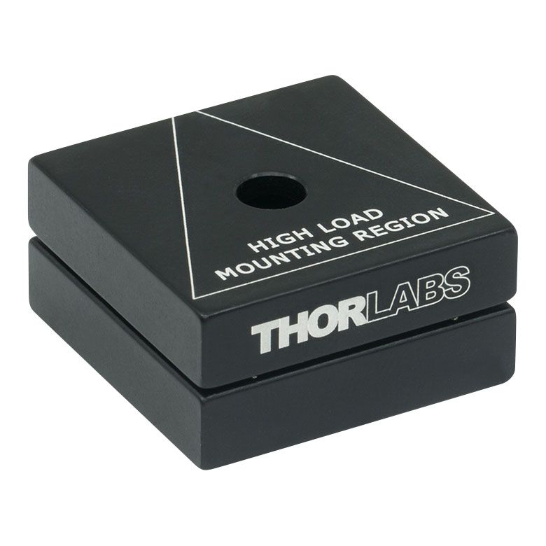
Figure G1.1 KB1X1 Kinematic Base
- Ball and V-Groove Design Allows High-Precision Positioning
- Top Plate Included in Complete Base (KBT1X1) Features an #8 (M4) Counterbore
- Alternate Top Plate (KBT1X1T) Features Four 8-32 (M4) Tapped Holes and a #8 (M4) Counterbore
- Bottom Plate has a #8 (M4) Counterbore
The top mounting plate and bottom base plate of the KB1X1 (KB25/M) kinematic base are magnetically coupled using two pairs of high-strength magnets which provide a holding force of 3.6 lbs. With a ball and V-groove design, the top plate can be inserted and removed with high repeatability. The top and bottom plate both have a center-located #8 (M4) counterbore hole which allows either plate to be mounted to a Ø1/2" post. Using an AE8E25E (AE4M6M) thread adapter, the plates can also be secured to a 1/4"-20 (M6) tapped optical table. Alternatively, the KBT1X1T and KBT25T/M top plates feature four 8-32 or M4 tapped holes, respectively. During angular repeatability testing, we obtained a mean of 6.36 µrad, a minimum of 0.58 µrad, and a maximum of 26.72 µrad. For information about repeatability testing of the KB1X1 and other kinematic bases, see the Repeatability tab.
")
 Zoom
Zoom
Click to Enlarge
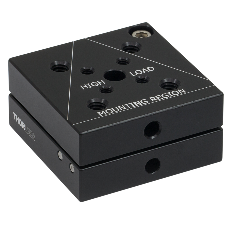
Figure G2.1 KB2X2 Kinematic Base
- Ball and V-Groove Design Allows High-Precision Positioning
- Top Plate Features Four 1/4"-20 (M6) Tapped Holes, Four 8-32 (M4) Tapped Holes, and a 1/4" (M6) Counterbore
- Bottom Plate Features a 1/4" (M6) Counterbore
- Top and Bottom Plates Available Individually or as Complete Unit
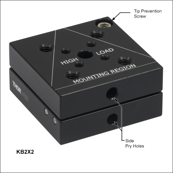
The top mounting plate and bottom base plate of the KB2X2 (KB50/M) kinematic base are magnetically coupled using two pairs of high-strength magnets which provide a holding force of 6.25 lbs. With a ball and V-groove design, the top plate can be inserted and removed with high repeatability. The top plate has a central 1/4" (M6) counterbore that can be used to attach a Ø1" post. Alternatively, an SD1 counterbore adapter can be used to make the top plate compatible with 8-32 components, such as Ø1/2" posts. Additionally, the KBT2X2 top plate features four 1/4"-20 (M6) tapped holes and four 8-32 (M4) tapped holes to provide flexible mounting options. The top plate of the KB2X2 is engraved with a triangle indicating the high-load mounting region.
The top and bottom plates also have blind holes in the side for inserting 5/32" (4 mm) ball drivers to pry the plates apart. Additionally, the KB2X2 features a 9/64" (3 mm) hex head cap screw for tip prevention that can be used to prevent the two plates from separating while in use. Individual top and bottom plates are also available for interchanging different optomechanical setups. However, the 8-32 (M4) cap screw for tip prevention is not included with the purchase of individual top and bottom plates. If you would like a KB2X2 with fewer magnets (weaker magnetic coupling), please contact Technical Support.
During angular repeatability testing, we obtained a mean of 11.87 µrad, a minimum of 3.60 µrad, and a maximum of 30.96 µrad. For information about repeatability testing of the KB2X2 and other kinematic bases, see the Repeatability tab.
")
 Zoom
Zoom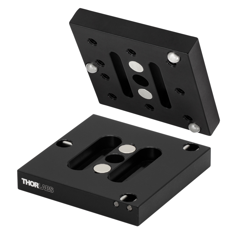
Click to Enlarge
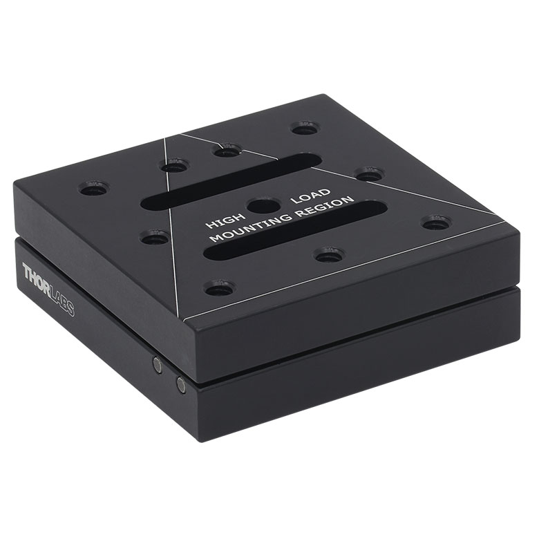
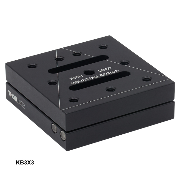
Figure G3.2 KB3X3 Kinematic Base
- Ball and V-Groove Design Allows High-Precision Positioning
- Top Plate Features a Center 1/4" (M6) Counterbore, Two 1/4" (M6) Counterbored Slots, and Nine 1/4"-20 (M6) Tapped Holes
- Bottom Plate Features a Center 1/4" (M6) Counterbore and Two 1/4" (M6) Counterbored Slots
- Top and Bottom Plates Available Individually or as Complete Unit
The top mounting plate and bottom base plate of the KB3X3 (KB75/M) kinematic base are magnetically coupled using two pairs of high-strength magnets which provide a holding force of 6.5 lbs. With a ball and V-groove design, the top plate can be inserted and removed with high repeatability. The top plate has a central 1/4" (M6) counterbore that can be used to attach a Ø1/2" post holder, while an array of nine 1/4"-20 (M6) tapped holes on the top plate provide the same mounting functionality as an optical breadboard. The top plate of the KB3X3 is engraved with a triangle indicating the high-load mounting region. Individual top and bottom plates are also available for interchanging different optomechanical setups.
During angular repeatability testing, we obtained a mean of 21.20 µrad, a minimum of 1.30 µrad, and a maximum of 81.90 µrad. For information about testing done on the repeatability of the KB3X3 and other kinematic bases, please see the Repeatability tab.
")
 Zoom
Zoom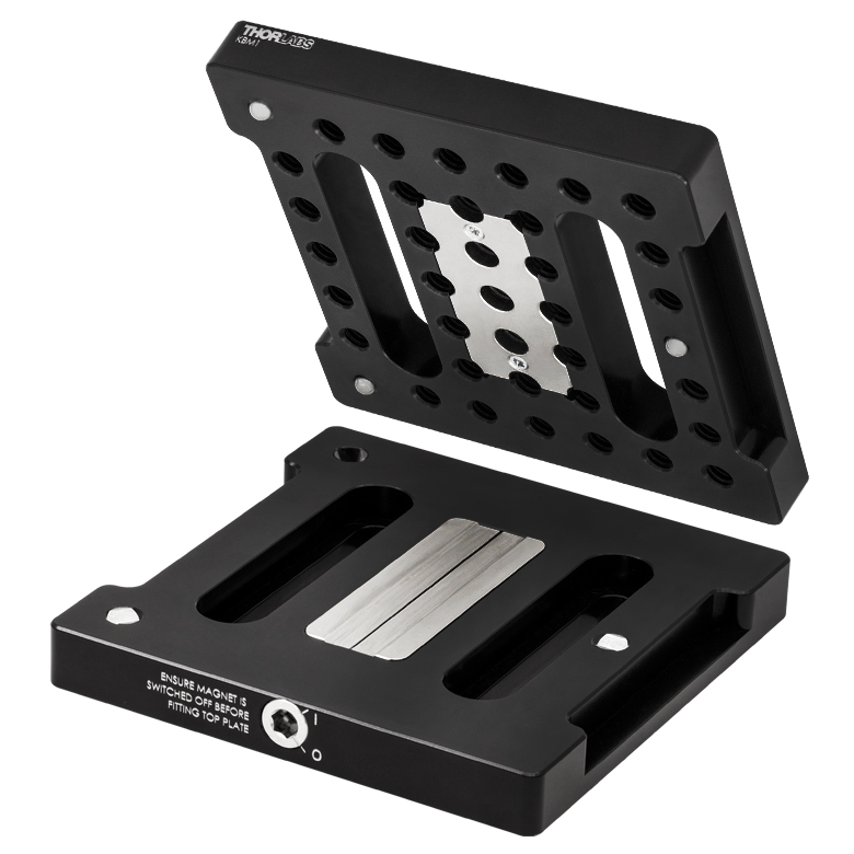
Click to Enlarge
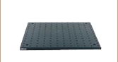
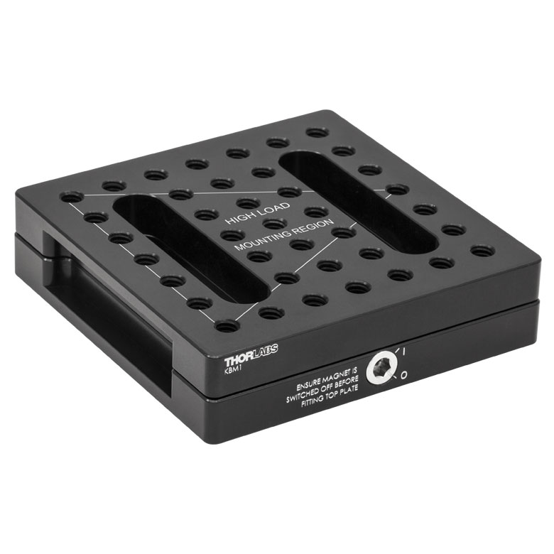
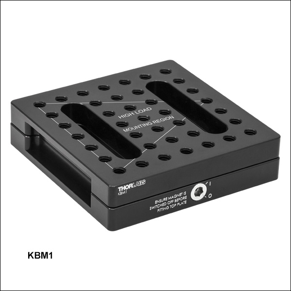
Figure G4.2 KBM1 Kinematic Breadboard
Click to Enlarge
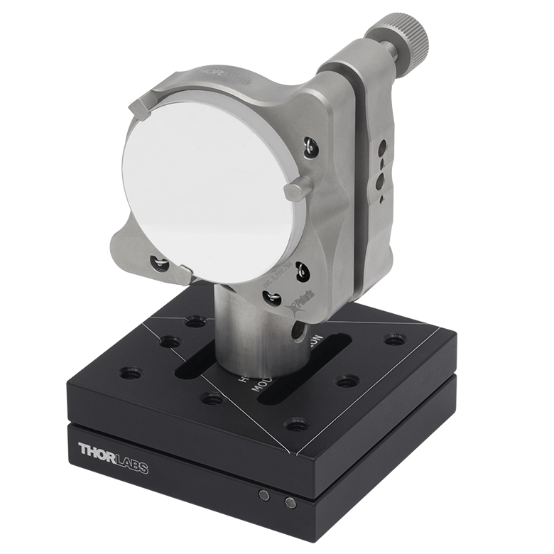
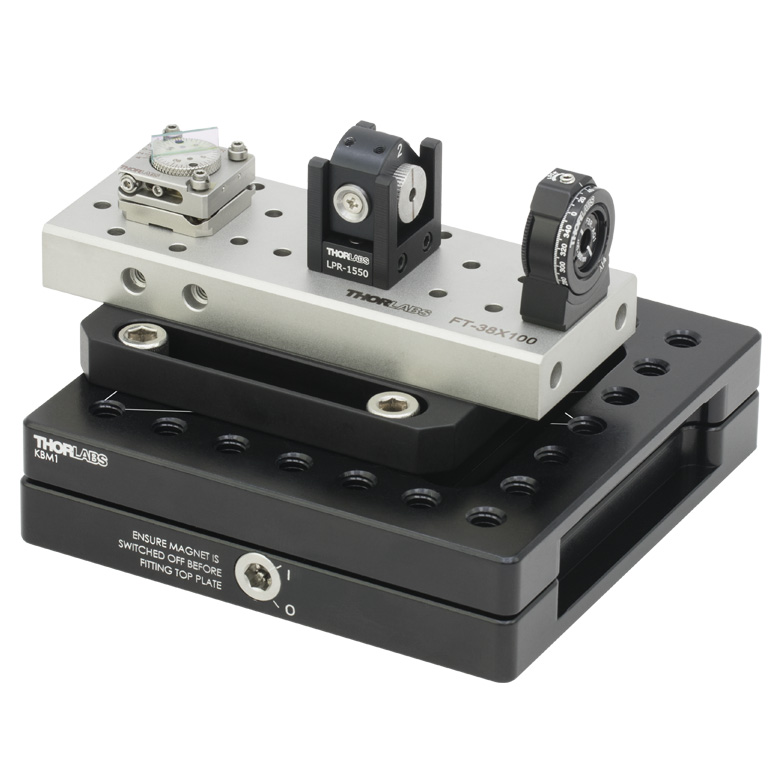
Figure G4.1 FiberBench Mounted on KBM1 Base
- Magnetic Holding Force of 40 N
- Ball and V-Groove Design Allows High-Precision Positioning
- Top Plate Offers 39 1/4"-20 (M6) Tapped Holes for Mounting
- Top and Bottom Plates Available Individually or as Complete Unit
The KBM1(/M) is a compact, high-precision, low-profile, lockable kinematic magnetic base, measuring 3.94" x 3.94" x 0.98" (100.0 mm x 100.0 mm x 25.0 mm). The top mounting plate and bottom base plate of the KBM1(/M) kinematic base (see Figure G4.2) are magnetically coupled using a high-strength magnet. The KBM1(/M) features a ball and V-groove design with a removable top plate. Individual top and bottom plates are also available for interchanging different optomechanical setups.
The top plate has an array of 39 1/4"-20 (M6) tapped holes [0.46" (11.8 mm) deep] spaced 0.5" (12.5 mm) apart and provides the same mounting functionality as an optical breadboard. The bottom plate has two 2.00" (50.0 mm) long counterbored slots for 1/4"-20 (M6) cap screws for mounting to an optical table. The magnetic force between the two plates is switched on and off by turning the switching screw through 90° using a 3/16" (5 mm) hex wrench. The magnetic switch design allows for the top plate to be mounted with less risk of damage or misalignment to precision components and fragile payloads.
Please note that the switch in the base should be set to off before placing the top to avoid damaging the kinematic seats. The switch can be engaged once the top has been installed. Maximum stability in the top plate can be achieved by keeping the center of mass of optomechanics mounted on the plate within the triangular region between the kinematic seats (see Figures G4.1 and G4.2).
Figure G4.1 shows the KBM1 being used with our FT-38X135 FiberBench. The FiberBench system is designed to couple fiber optic setups into free space and facilitates the quick exchange, insertion, or removal of optical components while maintaining the same optical axis.

 Zoom
ZoomClick to Enlarge Figure G5.1 KBS98 Kinematic Seats Can Be Used to Convert a Breadboard into a Kinematic Platform
- Converts Any Breadboard into Kinematic Platform
- Ball and V-Groove Design Allows High-Precision Positioning
- Seats Offer Universal 1/4" (M6) Counterbores for Breadboard Mounting
- Top and Bottom Plate Sets Available Individually or as Complete Unit
The KBS98 kinematic seats can be used to convert any imperial or metric breadboard into a kinematic platform that can be removed and replaced with a high degree of accuracy. The KBS98 consists of six plates. Three of the plates, which are referred to as the bottom set, have V-groove slots and should be mounted on the stationary optical table or breadboard. The other three plates, which are referred to as the top set, have an inset ball that will sit in the V-groove of the bottom plate. Each seat has a high-strength magnet which, when used together with another seat, provides a holding force of 10 lbs.
The top plates should be attached to the optical breadboard that is being taken out of and put back into an optical setup. The seats should be arranged in a triangular pattern near the corners/edge of the optical breadboard with the V-grooves in the bottom plates aligned so that the three axes defined by the V-grooves intersect at a common point. Proper positioning of the plates is necessary in order to maximize the stability of the optical breadboard.
")
 Zoom
Zoom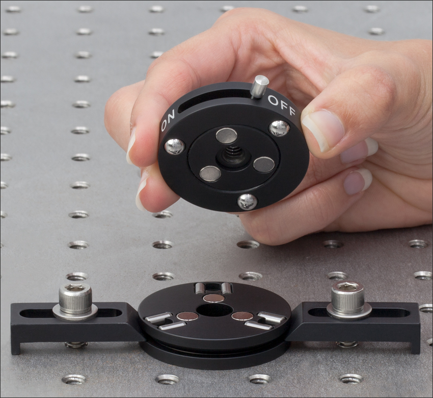
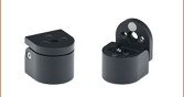
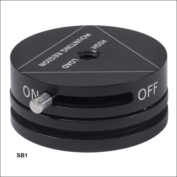
Click to Enlarge Figure G6.1 SB1 Kinematic Base Mounted to an Optical Table with CL6 Table Clamps
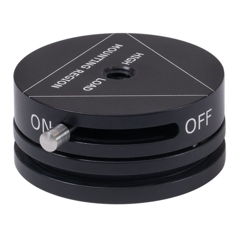
- On/Off Switch to Connect/Disconnect Plates
- SB1(/M) Includes 1/4"-20 (M6) Tapped Top Plate and 1/4" (M6) Counterbored Bottom Plate
- Top Plate with Centered 8-32 Tap Available
The SB1(/M) round kinematic base is comprised of both a top plate and a bottom plate. The top plate can be easily removed and replaced with an ON/OFF switch that interrupts the magnetic force coupling the plates of the base. When set to ON, high-strength magnets in the base provide a holding force of 4.5 lbs. With a ball and V-groove design, the top plate will automatically reposition to an exact location with high repeatability. The bottom plate has a centered 1/4"-20 (M6) through hole counterbored for a caphead screw that allows the base to be mounted to an optical table. Alternatively, CL6 table clamps can be used in the groove of the bottom plate to fix the base in an arbitrary position on an optical table, as shown in Figure G6.1. During angular repeatability testing, we obtained a mean of 11.21 µrad, a minimum of 0.52 µrad, and a maximum of 159.47 µrad. For information about testing done on the repeatability of the SB1 and other kinematic bases, please see the Repeatability tab.
The SB1(/M) round kinematic base ships with the SB1T(/M) top plate with a 1/4"-20 (M6) tap and the SB1B bottom plate. Note that the SB1T8 top plate with an 8-32 tap and the SB1T4/M top plate with an M4 tap are compatible with both the SB1T(/M) and SB1B, and must be purchased separately for more threading options.
")
 Zoom
Zoom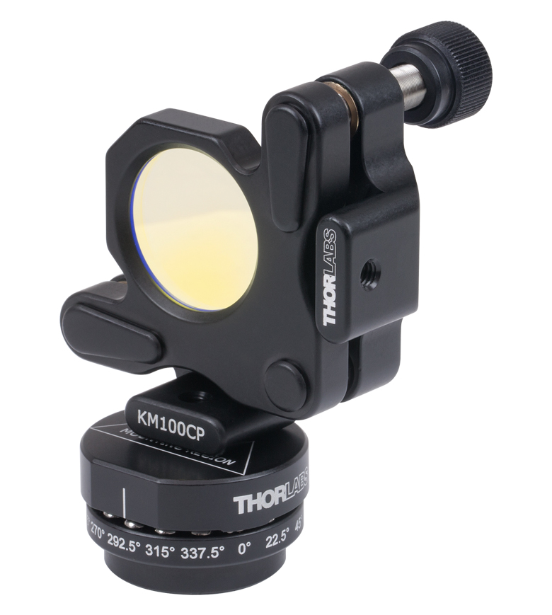
Click to Enlarge
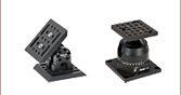
Figure 509A Kinematic mounts, such as the KM100CP, can be mounted to the NX1NF to allow for tip and tilt adjustments.
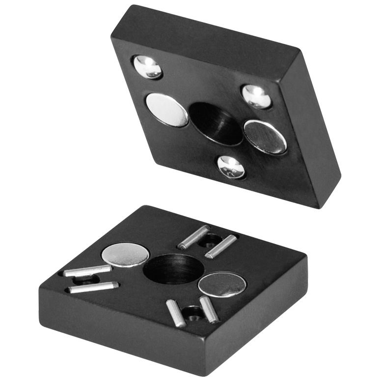
Click to Enlarge
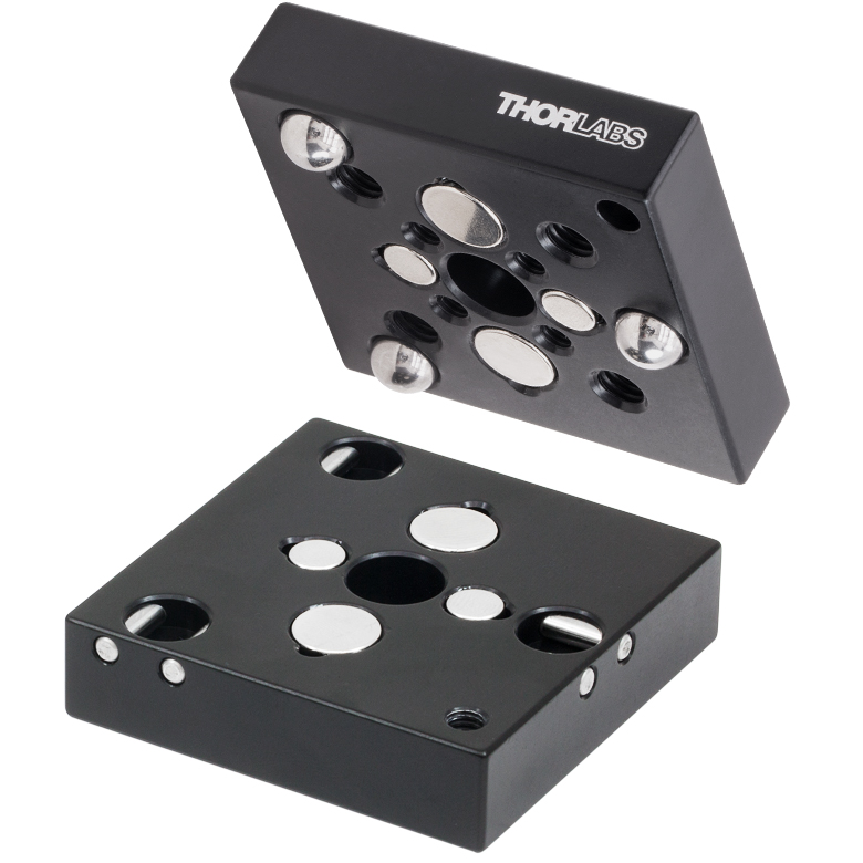
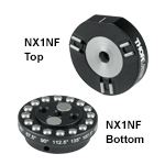
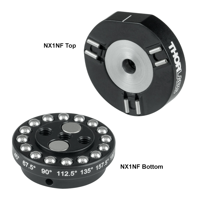
Figure 509B Top and Bottom Plates of the NX1NF(/M)
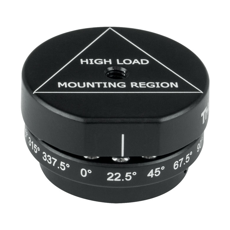
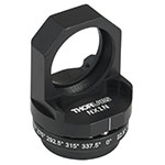
- Indexed with 16 Positions at 22.5° Increments
- Top Plate has an 8-32 (M4) Tap for Component Mounting
- Three 8-32 (M4) Tapped Mounting Holes in Bottom Plate
- Easy, Repeatable Exchange of Optical Components
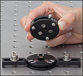
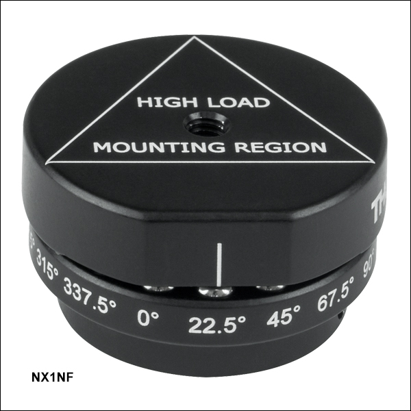
The NX1NF(/M) Indexing Base features 16 indexed positions every 22.5° allowing mounted components to be held at both 45° and 90°. The angular positions are engraved on the base plate for fast alignment. The top plate returns to any given position, indicated by an engraved witness line, with high repeatability. This mount is ideal for redirecting a laser to multiple targets on an optical table, as well as for precise switching of shared laser systems.
For maximum stability, the center of gravity of components mounted to the top plate, NX1NFT(/M), should be located within the designated mounting region, which is marked with an engraving.
Neodymium iron magnets couple the top and bottom plates while stainless steel ball bearings and V-grooves provide the 16 indexing positions. Three 8-32 (M4) tapped mounting holes in the bottom plate allow the mount to be secured to a Ø1/2" post. A small through hole, located directly under the 90° engraving on the bottom plate, accepts a 5/64" (2 mm) balldriver to help provide enough torque when attaching the mount to the post. The magnets in the NX1NF provide a holding force of 1.5 lbs between the top and bottom plates. During angular repeatability testing, we obtained a mean of 10.6 µrad, a minimum of 0.38 µrad, and a maximum of 140.50 µrad. For information about testing done on the repeatability of the NX1NF and other kinematic bases, please see the Repeatability tab.
Please Note: The top plate of this indexing mount is compatible with the bottom plate of the NX1N(/M) 16-position, indexing mount (sold below).

 Zoom
Zoom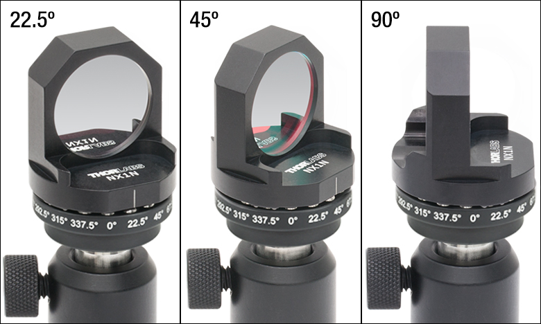
Click to Enlarge
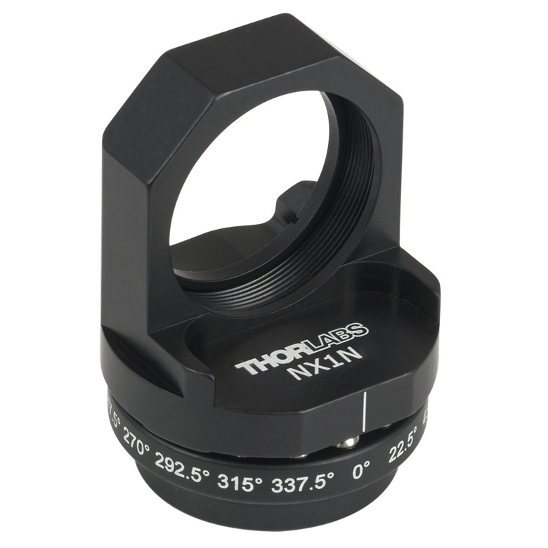
Figure 440A The NX1N(/M) Indexing Mount can hold an optic at any one of 16 positions, including 45° and 90°.
- Indexed with 16 Positions at 22.5° Increments
- Holds Ø1" Optics up to 7 mm (0.27") Thick
- Three 8-32 (M4) Mounting Holes in Bottom Plate
- Easy, Repeatable Exchange of Optical Components
The NX1N(/M) Indexing Mount for Ø1" optics features 16 indexed positions every 22.5°, allowing the optic to be held at both 45° and 90°. This mount is ideal for redirecting a laser to multiple targets on an optical table, and its angular positions are engraved on the base plate for fast alignment. The top plate returns to any given position, indicated with the engraved witness line, with a high repeatability. During angular repeatability testing, we obtained a mean of 10.6 µrad, a minimum of 0.38 µrad, and a maximum of 140.50 µrad. For information about testing done on the repeatability of the NX1N and other kinematic bases, please see the Repeatability tab.
The included SM1 (1.035"-40) retaining ring (SM1RR) secures the optic against the front lip of the mount. This indexing mount can hold optics that are no greater than 7 mm (0.27") thick. Neodymium iron magnets couple the top and bottom plates, while stainless steel ball bearings and V-grooves provide the 16 indexed positions. Three 8-32 (M4) tapped mounting holes in the bottom plate allow the mount to be secured to a Ø1/2" post. A small through hole, located directly under the 90° engraving on the bottom plate, accepts a 5/64" (2.00 mm) balldriver to help provide enough torque when attaching the mount to the post.
Please Note: The top plate of this indexing mount is compatible with the bottom plate of the NX1NF (NX1NF/M) 16-position, indexing mounting base.