 Products Home / Optomechanical Components / Vacuum Components / Vacuum-Compatible Adjusters & Actuators / Vacuum-Compatible Piezoelectric Inertia Actuators
Vacuum-Compatible Piezoelectric Inertia Actuators
- Vacuum-Compatible Down to 10-6 Torr
- 10 mm, 13 mm, 25 mm, or 50 mm Travel Range
- Ideal for Set-and-Hold Applications that Require
High-Resolution Relative Positioning
MPIA10VF
10 mm Travel Range,
3/16"-130 Mounting Thread
for Select Polaris Ø1/2" Mounts
Application Idea
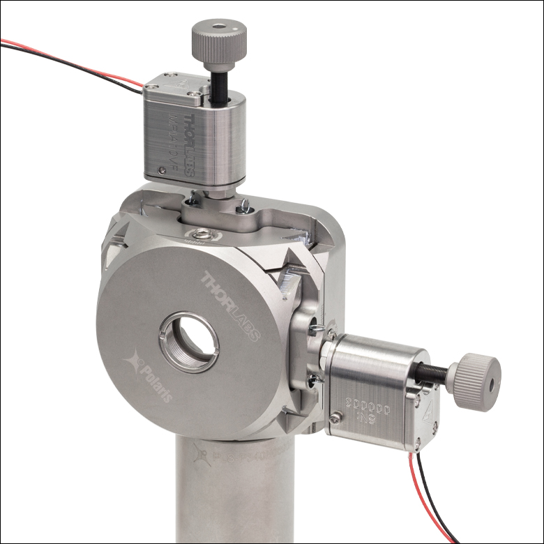
Two MPIA10VF Piezo Inertia Actuators can be used
in place of the 3/16"-130 adjustment screws
in our POLARIS-K05 Mirror Mount.
PIAK10VF
10 mm Travel Range,
1/4"-100 Mounting Thread
for the KS1TV Mirror Mount
PIA25VF
25 mm Travel Range,
Ø3/8" Mounting Barrel
for Translation Stages


Please Wait
| Table 1.1 Key Specificationsa | |||||
|---|---|---|---|---|---|
| Item # | MPIA10VF | PIAK10VF | PIA13VF | PIA25VF | PIA50VF |
| Travel | 10 mm | 10 mm | 13 mm | 25 mm | 50 mm |
| Step Sizeb,c | 10 - 20 nm (Typ.), ≤30 nm (Max) |
10 - 30 nm (Typ.), ≤30 nm (Max) |
|||
| Step Size Adjustabilityd | Up to 30% | ||||
| Active Preload | 13 N Maxe | 30 N Maxf | 25 N Maxf | ||
| Speed (Continuous Stepping)b,c |
1.2 - 2.4 mm/min. (Typ.), ≤3.6 mm/min. (Max) |
1.2 - 3.6 mm/min. (Typ.), ≤3.6 mm/min. (Max) |
|||
| Motor Type | Piezoelectric Inertia | ||||
| Primary Mounting Feature | 3/16"-130 Thread |
1/4"-100 Threadg |
Ø3/8" (Ø9.525 mm) Barrelh | ||
| Vacuum Rating | 10-6 Torr | ||||
| Bakeout Temperature | 130 °C Max | ||||
| Operating Voltage | 130 V Max | 125 V Max | |||
| Required Controlleri | KIM001 or KIM101 | ||||
Features
- Compact Motor Housings:
- MPIA10VF: 20.7 mm x 14.6 mm (W x H)
- PIA Series: 31.5 mm x 17.0 mm (W x H)
- Manual Adjustment via Knob on Adjuster Screw
- Rated Down to 10-6 Torr
- Variants with Mounting Threads for Compatibility with Kinematic Mounts or Ø3/8" Barrel for Linear Translation Stages (See Table 1.1 for Details)
- Ideal for Set-and-Hold Applications that Require High-Resolution Relative Positioning
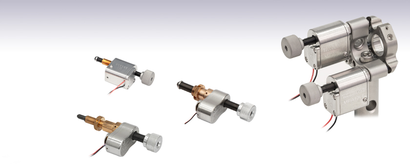
Thorlabs' Vacuum-Compatible Piezoelectric Inertia Actuators provide high-resolution linear motion control with no backlash and long piezo translation ranges in compact, vacuum-compatible packages. The step size can be adjusted up to 30% to a maximum of 30 nm using the KIM001 or KIM101 Controllers (sold separately below). Due to the open-loop design, hysteresis, and application conditions, the achieved step size of the system can vary by up to 20% and is not normally repeatable. An external feedback system will need to be used to overcome this variance. We also offer standard piezo inertia actuators for non-vacuum applications.
These actuators are self-locking when at rest and when there is no power supplied to the piezo, making them ideal for set-and-hold applications that require nanometer resolution and long-term alignment stability. Manual adjustments can be made using the knob on the adjuster screw, as long as the piezo is not actively translating the screw; the knob is also compatible with 5/64" (2.0 mm) hex keys.
Powered by discrete piezo stacks, these actuators operate at speeds of up to 3.6 mm/minute. The design of the piezo motor, detailed below, will rotate the tip of the lead screw during translation.
Mounting Options
The MPIA10VF actuator features a 3/16"-130 threaded barrel for compatibility with Polaris Ø1/2" optic mounts that use 3/16"-130 adjuster screws. The PIAK10VF actuator features a 1/4"-100 threaded barrel for compatibility with the KS1TV mirror mount or other mounts that don't require matched 1/4"-100 actuators. Note that this actuator is not compatible with our Polaris mirror mounts; see below for details.
The PIA13VF, PIA25VF, and PIA50VF actuators each have a Ø3/8" (Ø9.525 mm) barrel that can be mounted in a manual stage that has a Ø3/8" mounting clamp.
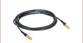
Each actuator has an integrated 0.75 m flying lead and is shipped with 1.0 m of SMC-terminated coaxial cable for wiring outside the vacuum chamber. The flying leads and cored cable lengths can be cut down as needed, but the total length (inside and outside) should not exceed 2.0 m.
Required Controller
A KIM001 or KIM101 Controller, available below, is required to operate these piezo inertia actuators; they cannot be driven using a standard piezo controller. These drivers have an internal sawtooth voltage signal generator capable of sending sub-millisecond pulses (steps) with controllable amplitudes from 85 V to 125 V.
Click to Enlarge
Simplified Illustration Showing the Operation of an Inertia Piezo Actuator
Piezoelectric Inertia "Slip-Stick" Motor
A piezo stack mounted perpendicular to the lead screw axis actuates the screw via a design based on the system's inertia and coefficients of friction. Two decoupled arms, or jaws, are located on either side of the piezo. These arms extend across the top and bottom of the main lead screw, as illustrated in the diagram to the left.
The piezo reacts to a custom sawtooth voltage waveform, causing it to expand or contract. The waveform is asymmetric, slowly ramping up to the specified voltage and then quickly dropping the voltage to zero on a nanosecond timescale. As shown in the bottom illustration to the left, the jaws will "stick" to the lead screw during the slow voltage ramp due to static friction, turning the screw similar to a person using their thumb and forefinger. The nanosecond voltage drop will cause the arms to "slip" due to the screws' inertia and the lower coefficient of dynamic friction, allowing the arms to return to their original position without undoing the rotation of the screw. This mechanism allows a single piezo element to translate a lead screw along its entire length.
Due to a number of factors that include the application conditions, piezo hysteresis, component variance, and the axial load, the achieved step size will vary and is not repeatable. To help overcome this variance, an external feedback system will need to be used. Alternatively, a stepper motor actuator can also be substituted depending on the application.
| Item #a | MPIA10VF | PIAK10VF | PIA13VF | PIA25VF | PIA50VF |
|---|---|---|---|---|---|
| Travel | 10 mm (0.39") | 10 mm (0.39") | 13 mm (0.51") | 25 mm (0.98") | 50 mm (1.97") |
| Step Sizeb,c | 10 - 20 nm (Typ.), ≤30 nm (Max) | 10 - 30 nm (Typ.), ≤30 nm (Max) | |||
| Step Size Adjustabilityd | Up to 30% Max | ||||
| Step Frequency | 2 kHz Max | ||||
| Backlash | None | ||||
| Active Preload | 13 N Maxe | 30 N Maxf | 25 N Maxf | ||
| Angular Resolution | 1.1 μrad (Typ.)g with POLARIS-K05 Ø1/2" Mirror Mount |
0.5 µrad (Typ.) with KS1TV Ø1" Mirror Mount |
N/A | ||
| Recommended Max Active Axial Load Capacityh |
N/A | 2.5 kg (5.5 lbs) | |||
| Speed (Continuous Stepping)b,c |
1.2 - 2.4 mm/min. (Typ.), ≤3.6 mm/min. (Max) |
1.2 - 3.6 mm/min. (Typ.), ≤3.6 mm/min. (Max) | |||
| Drive Screw | 6-80 Thread, Hard PVD Coated |
1/4"-80 Thread, Hard PVD Coated | |||
| Actuator Tip | Tungsten-Carbide-Coated Ball | ||||
| Lifetime | >1.5 x 10⁸ Steps | >1 Billion Steps | |||
| Motor Type | Piezoelectric Inertia | ||||
| Piezo Specifications | |||||
| Operating Voltage | 130 V Max | 125 V Max | |||
| Capacitance | 100 nF | 175 nF | |||
| Resonant Frequency | 250 kHz | 125 kHz (No Load) | |||
| Physical Specifications | |||||
| Dimensionsi (L x W x H) |
48.9 mm x 20.7 mm x 14.6 mm (1.93" x 0.81" x 0.57") |
77.7 mm x 31.5 mm x 17.0 mm (3.06" x 1.24" x 0.67") |
59.4 mm x 31.5 mm x 17.0 mm (2.34" x 1.24" x 0.67") |
72.0 mm x 31.5 mm x 17.0 mm (2.83" x 1.24" x 0.67") |
97.0 mm x 31.5 mm x 17.0 mm (3.82" x 1.24" x 0.67") |
| Mass | 30.5 g (1.08 oz) with Flying Leads Only |
55 g (1.94 oz) with Flying Leads Only |
55 g (1.94 oz) with Flying Leads Only |
60 g (2.12 oz) with Flying Leads Only |
65 g (2.29 oz) with Flying Leads Only |
| Mounting Feature (Auxiliary) |
3/16"-130 Thread with Lock Nut |
1/4"-100 Thread with Lock Nutj (Ø3/8" [Ø9.525 mm] Barrel) |
Ø3/8" (Ø9.525 mm) Barrel (3/8"-40 Thread with Lock Nut) |
||
| Vacuum Rating | 10-6 Torr | ||||
| Operating Temperature | 10 to 40 °C | 5 to 40 °C | |||
| Bakeout Temperature | 130 °C Max | ||||
| Cable Length | 0.75 m (2.5 ft) Flying Lead for Vacuum, 1.0 m (3.3 ft) of Cored Cable for Wiring Outside Chamber |
||||
| Connector Type | SMC Female | ||||
| Cable Exit Adjustability | Fixed | ±55° for Left- or Right-Hand Exit | |||
| Compatible Controllerk | KIM001 or KIM101 | ||||
Software
Kinesis Version 1.14.58
The Kinesis Software Package, which includes a GUI for control of Thorlabs' Kinesis system controllers.
Also Available:
- Firmware Update Utilities
- Communications Protocol

Figure 58A Kinesis GUI Screen
Thorlabs offers the Kinesis software package to drive our wide range of motion controllers. The software can be used to control devices in the Kinesis family, which covers a wide variety of motion controllers ranging from small, low-powered, single-channel drivers (such as the K-Cubes®) to high-power, multi-channel benchtop units and modular 19" rack nanopositioning systems (the MMR60x Rack System).
The Kinesis Software features .NET controls which can be used by 3rd party developers working in the latest C#, Visual Basic, LabVIEW™, or any .NET compatible languages to create custom applications. Low-level DLL libraries are included for applications not expected to use the .NET framework and APIs are included with each install. A Central Sequence Manager supports integration and synchronization of all Thorlabs motion control hardware.
By providing this common software platform, Thorlabs has ensured that users can mix and match any of our motion control devices in a single application, while only having to learn a single set of software tools. In this way, it is perfectly feasible to combine any of the controllers from single-axis to multi-axis systems and control all from a single, PC-based unified software interface.
The software package allows two methods of usage: graphical user interface (GUI) utilities for direct interaction with and control of the controllers 'out of the box', and a set of programming interfaces that allow custom-integrated positioning and alignment solutions to be easily programmed in the development language of choice.
Thorlabs' Kinesis software features new .NET controls which can be used by third-party developers working in the latest C#, Visual Basic, LabVIEW™, or any .NET compatible languages to create custom applications.
C#
This programming language is designed to allow multiple programming paradigms, or languages, to be used, thus allowing for complex problems to be solved in an easy or efficient manner. It encompasses typing, imperative, declarative, functional, generic, object-oriented, and component-oriented programming. By providing functionality with this common software platform, Thorlabs has ensured that users can easily mix and match any of the Kinesis controllers in a single application, while only having to learn a single set of software tools. In this way, it is perfectly feasible to combine any of the controllers from the low-powered, single-axis to the high-powered, multi-axis systems and control all from a single, PC-based unified software interface.
The Kinesis System Software allows two methods of usage: graphical user interface (GUI) utilities for direct interaction and control of the controllers 'out of the box', and a set of programming interfaces that allow custom-integrated positioning and alignment solutions to be easily programmed in the development language of choice.
For a collection of example projects that can be compiled and run to demonstrate the different ways in which developers can build on the Kinesis motion control libraries, click on the links below. Please note that a separate integrated development environment (IDE) (e.g., Microsoft Visual Studio) will be required to execute the Quick Start examples. The C# example projects can be executed using the included .NET controls in the Kinesis software package (see the Kinesis Software tab for details).
 |
Click Here for the Kinesis with C# Quick Start Guide Click Here for C# Example Projects Click Here for Quick Start Device Control Examples |
|
LabVIEW
LabVIEW can be used to communicate with any Kinesis-based controller via .NET controls. In LabVIEW, you build a user interface, known as a front panel, with a set of tools and objects and then add code using graphical representations of functions to control the front panel objects. The LabVIEW tutorial, provided below, provides some information on using the .NET controls to create control GUIs for Kinesis-driven devices within LabVIEW. It includes an overview with basic information about using controllers in LabVIEW and explains the setup procedure that needs to be completed before using a LabVIEW GUI to operate a device.
 |
Click Here to View the LabVIEW Guide Click Here to View the Kinesis with LabVIEW Overview Page |
|
| Posted Comments: | |
| No Comments Posted |

 Zoom
Zoom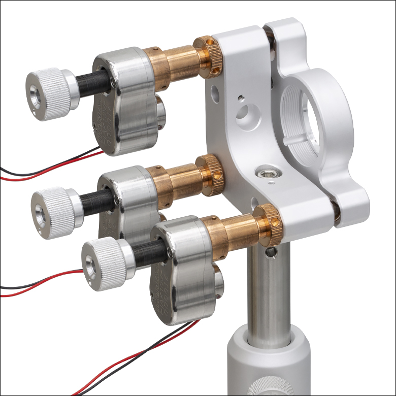
Click to Enlarge
Figure G1.3 KS1TV Mirror Mount with PIAK10VF Actuators Attached
(Each Sold Separately)
Click to Enlarge
Figure G1.2 POLARIS-05XY Ø1/2" Optic Translation Mount with MPIA10VF Actuators Attached
(Each Sold Separately)

Click to Enlarge
Figure G1.1 POLARIS-K05 Ø1/2" Mirror Mount with MPIA10VF Actuators Attached
(Each Sold Separately)
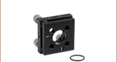
- MPIA10VF: 3/16"-130 Threaded Mounting Barrel for Compatibility with Select Polaris Ø1/2" Optic Mounts
- PIAK10VF: 1/4"-100 Threaded Mounting Barrel for Compatibility with KS1TV Mirror Mount
- High-Resolution Linear Motion with 10 mm Travel
- KIM001 or KIM101 Controller Required for Operation (Sold Separately Below)
These actuators feature threaded barrels which allow them to be used in place of manual actuators on select kinematic mounts. They provide high-resolution linear motion control over a 10 mm translation range in a compact package.
The MPIA10VF actuator features a 3/16"-130 threaded barrel for compatibility with Polaris Ø1/2" optic mounts that use 3/16"-130 adjuster screws. The PIAK10VF actuator features a 1/4"-100 threaded barrel for compatibility with our KS1TV mirror mount. The control cable of the PIAK10VF actuator can be adjusted up to 110° for space-constrained applications (click here for a photo).
Note that the PIAK10VF actuator is not compatible with Polaris mounts that use 1/4"-100 adjusters. These mounts require a specific actuator ball size and tip design to ensure that the ball contact is centered on the sapphire end stone and that there is proper screw clearance during full translation. In the case of the PIAK10VF actuator, the side of the screw, rather than the ball tip, will contact the sapphire end stone and, as a result, the actuator should not be used with Polaris mounts.
These actuators can provide nanometer resolution with long-term alignment stability. Manual adjustments can be made using the knob on the adjuster screw, as long as the piezo is not actively translating the screw; the knob is also compatible with 5/64" (2.0 mm) hex keys. The piezoelectric elements are self-locking when at rest and when there is no power supplied to the piezo, making them ideal for set-and-hold applications. As a result, any drift is due to the lead screw of the actuator.
Please note that the "slip-stick" nature of these devices uses very short pulse widths and continuous stepping of the actuator will result in an audible noise at a typical level of 60 to 70 dB.

 Zoom
Zoom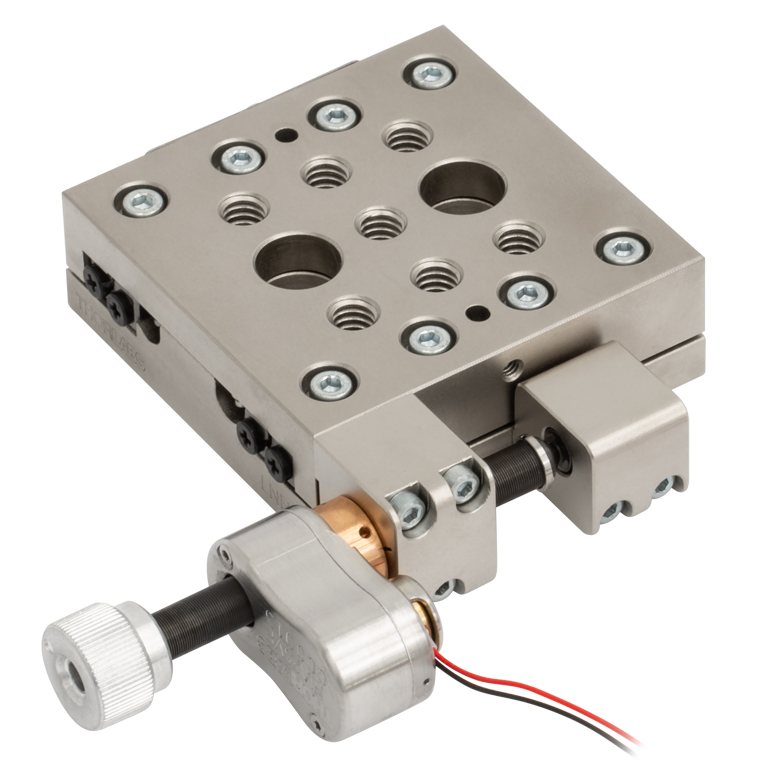
Click to Enlarge
Figure G2.2 PIA25VF Inertia Actuator Used in Place of the Micrometer in our LNR25M(/M) Translation Stage (Contact Tech Sales to Request a Vacuum-Compatible Version of the Stage)
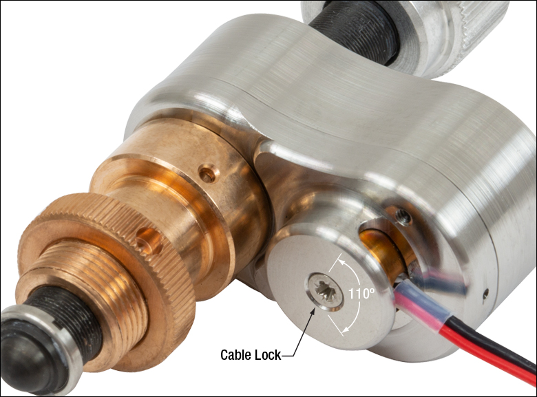
Click for Details
Figure G2.1 The flying lead can be adjusted up to 110° for
- Ø3/8" (Ø9.525 mm) Barrel for Mounting to Manual Stages with Ø3/8" (Ø9.525 mm) Mounting Clamps
- High-Resolution Linear Motion with Up to 50 mm Travel
- KIM001 or KIM101 Controller Required for Operation (Sold Separately Below)
These actuators feature Ø3/8" barrels that allow them to be used as compact motorized replacements for manual drive screws or micrometers on many of our translation stages. They provide nanometer resolution with long-term alignment stability over a translation range as long as 50 mm. Manual adjustments can be made using the knob on the adjuster screw, as long as the piezo is not actively translating the screw; the knob is also compatible with 5/64" (2.0 mm) hex keys. To order vacuum-compatible versions of our stages, please contact Tech Sales.
The "slip-stick" nature of this device uses very short pulse widths and continuous stepping of the actuator will result in an audible noise at a typical level of 60 to 70 dB.

 Zoom
Zoom| Key Specificationsa | ||
|---|---|---|
| Item # | KIM001 | KIM101 |
| Piezoelectric Outputs (SMC Male) | One | Four |
| Piezo Output Voltage | 85 to 125 VDC | 85 to 125 VDC per Channel |
| Top Panel Controls | Scroll Wheel | Dual-Axis Joystick |
| External Input (SMA Female) |
±10 V ± 2% | |
| Input Power | +15 VDC @ 2 A | |
| Housing Dimensionsb |
60.0 mm x 60.0 mm x 47.0 mm (2.36" x 2.36" x 1.85") |
121.0 mm x 60.0 mm x 47.0 mm (4.76" x 2.36" x 1.85") |
| Compatible Software | Kinesis | Kinesis |
- For complete specifications, please see the manuals by clicking the red Docs icons (
 ) below.
 - Not Including Mounting Plate
- Compact Footprints
- Adjustable Voltage Output from 85 V to 125 V
- Single-Channel and Four-Channel Versions Available
- Standalone Operation via Top Panel Controls and Display or PC Control via USB Plug and Play
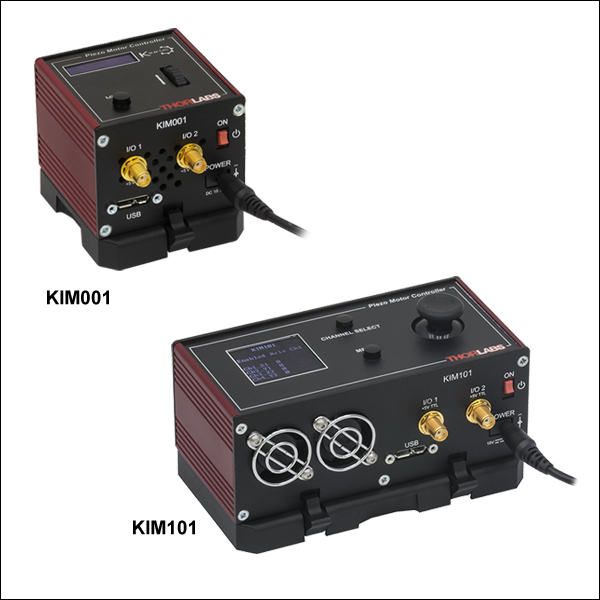
These compact K-Cube® Controllers provide easy manual and PC control of our piezo inertia stages, actuators, and optic mounts. They feature adjustable voltage output from 85 V to 125 V. The top panel display screen enables operation as soon as the unit is turned on, without the need for connection to a PC. Alternatively, both controllers have USB connectivity that provides 'Plug-and-Play' PC-controlled operation with our Kinesis software package (included).
These units have small footprints and may be mounted directly to the optical table using the 1/4" (M6) counterbored slots in the base plate. Their compact size allows these controllers to be positioned close to the motorized system for added convenience when manually adjusting motor positions using the top panel controls. Tabletop operation also allows minimal drive cable lengths for easier cable management.
Please note that these controllers do not ship with a power supply. The compatible KPS201 power supply is sold below.
KIM001 Single-Channel Controller
This single-channel piezo inertia controller provides a voltage output for a single piezo inertia stage or actuator. The top panel features a spring-loaded scroll wheel for driving the stage or actuator as well as selecting menu options.
KIM101 Four-Channel Controller
This four-channel controller features four SMC outputs to drive piezo inertia devices. The channels can be controlled independently or simultaneously in pairs using the dual-axis joystick on the controller's top panel. The controller can be configured to operate up to four PD series piezo inertia stages, up to four PIA series piezo inertia actuators, or up to two PIM series piezo inertia optic mounts; one KIM101 can only concurrently drive devices that use the same "Select Stage" configuration in the controller's menu options (see the manuals for more details).
For more information, please see the full web presentation.
Power Supply Options
The KIM001 and KIM101 Motor Controllers do not ship with a power supply. The compatible KPS201 Power Supply is sold separately below.
Note: Due to the nature of its design, and its non-linear high frequency switching, the KIM001 and KIM001 units are not compatible with the KEH3 or KEH6 hubs. Only use the KPS201 power supply unit.

 Zoom
Zoom- Power Supply Compatible with KIM001 and KIM101 Motor Controllers
- Universal Input: 100 - 240 VAC
- Region-Specific Adapter Plug Shipped with Power Supply
The KPS201 power supply outputs +15 VDC at up to 2.66 A and can power a single K-Cube® or T-Cube™ with a 3.5 mm jack. It plugs into a standard wall outlet. One region-specific plug adapter, selectable at checkout, is included with each power supply.