 Products Home
InnerVision® X-Ray Measurement Systems
- Non-Destructive Internal Coordinate Measurements
- 1.5 MP CMOS Flat Panel Detector
- Granite Base Ensures Thermal and Mechanical Stability
- Smooth, High-Speed Positioning with 0.1 µm Precision
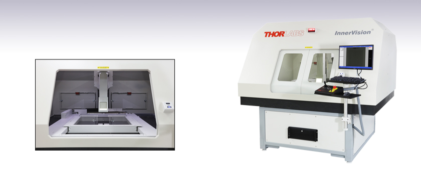
XA712
X-Ray Measurement System, 710 mm x 660 mm Range
X-Ray Coordinate Measurement System Interior


Please Wait

 Ike Jariel General Manager Thorlabs Measurement Systems |
Exploring the Options?Thorlabs' X-Ray Metrology Systems are customized to meet the demanding needs of your application. If you do not see a product or specification that you require or you are looking for assistance customizing our system, our team is happy to help.In the Budgetary Phase?System price can vary based on the exact components. Through our conversations, I can ensure your system quote is tailored to your requirements.OEM or Custom Projects?Click here to learn about our OEM capabilities.Want a System Demo?Contact us to demo a system in our showroom or remotely. |
I'm Happy to Assist! |
Inspection Applications
- Surface Mount Devices (SMD) and Plated Through Hole (PTH) Assemblies
- Single and Multi-Layer PCBs
- Ball Grid Arrays
- Reinforcements
- Fasteners in Composite Structures
- Encapsulated Objects
- Laminated Features
- Small Part Internal Inspection
- Small Hole Inspection in Electronics Assemblies
Features
- Non-Destructive Measurements of Internal Geometries
- XY Measuring Range Options:
- 710 mm x 660 mm (28" x 24")
- 1270 mm x 915 mm (50" x 36")
- High-Speed (500 mm/s) Translation using Linear Motors
- 2D Measurements with CNC and Manual Operation
- Ø5 µm Spot Size, 20 - 90 kV X-Ray Source for High-Resolution Images
- Stable Granite Base Ensures High Accuracy and Repeatability
- Ergonomic Workstation for Simple and Convenient Operation
- Advanced, Feature-Rich MetLogix® M3 Metrology Control Software
- Optional Accessories for Added Functionality and Flexibility
- Hinged Polycarbonate Platen to Retain Thin Electronics
- Radiation Meter to Monitor X-Ray Leakage
- Calibration Grid to Ensure Accuracy and Orthogonality
Thorlabs' InnerVision® X-Ray Measurement Systems are robust coordinate measuring systems that utilize an X-ray source to measure and locate internal or surface-level features of electronics or other small devices. Automated protocols enable inspection of large volumes of parts sequentially or simultaneously. With tolerance reports and export utilities, thresholds can be set to enable timely corrections to a production process or, when necessary, interruption of production to minimize scrap.
Each metrology system is supported by a granite base to provide the utmost measurement stability. Balanced, non-contact, magnetic linear motors with air bearings are used to position the XY stage quickly, quietly, and accurately. The system's X-ray source, located under the polycarbonate stage platform, has a Ø5 µm spot size at 4 W of electrical power and a 20 kV to 90 kV voltage range (maximum electrical power of 8 W). This can easily penetrate common circuit board materials such as copper and fiberglass up to 0.5" thick, in addition to a variety of plastics and composites with lower X-ray scattering. An X-ray collection path is cantilevered with granite support over the stage. This includes a radiation shield and a 1.5 MP CMOS flat panel detector to collect, process, and record the transmission signal through the sample.
Please see the Design Features and Specs tabs for more details on the systems. The base systems can be upgraded to include additional accessories, including a hinged polycarbonate platen, radiation meter, and calibration grid. Please see the Accessories tab for details on these options.
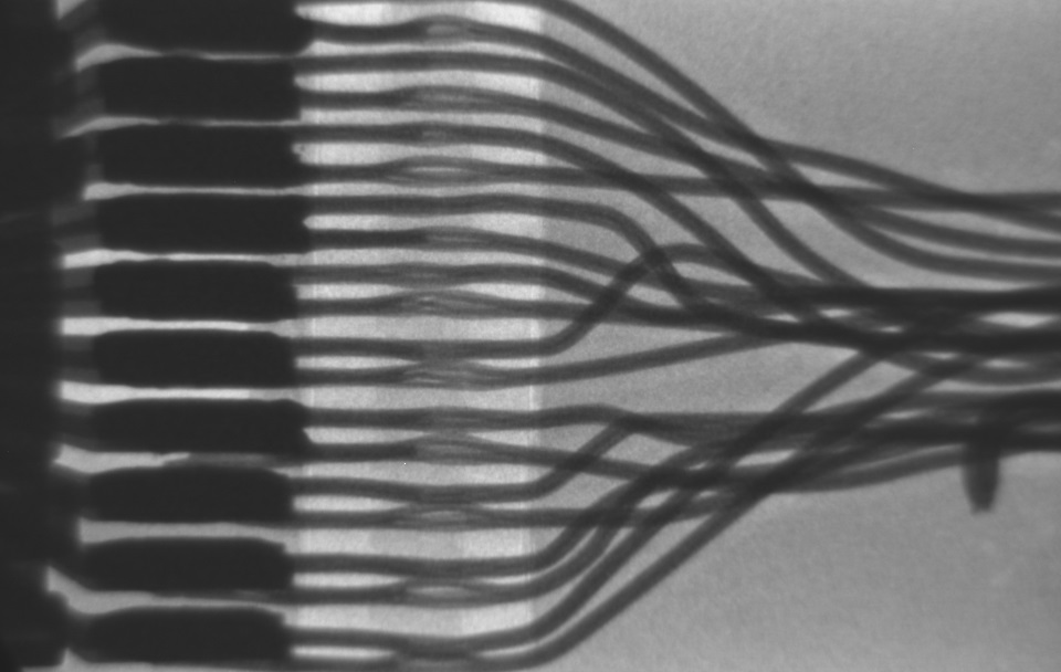
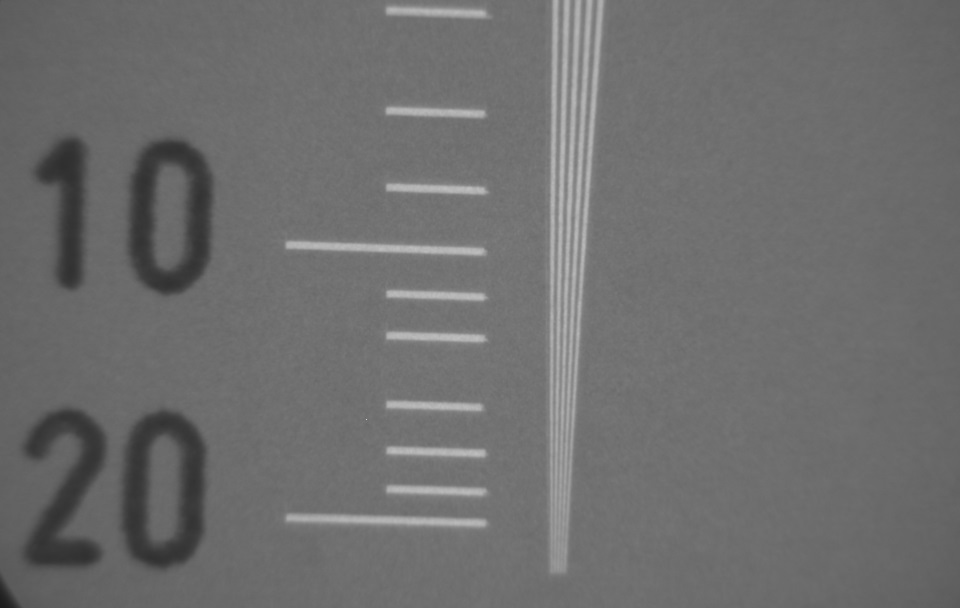
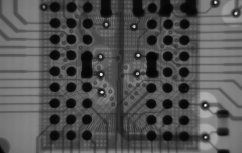
Images Taken Using the InnerVision X-Ray Measurement System

Exploring the Options?
Thorlabs' X-Ray Measurement Systems are customized to meet the demanding needs of your application. If you do not see a product or specification that you require or you are looking for assistance selecting a system, please contact me. Our Measurement Systems Team is happy to help and can provide system recommendations based on your needs.
Ike Jariel
General Manager
Thorlabs Measurement Systems
The InnerVision® X-Ray Measurement Systems are designed for high performance in demanding industrial applications. Key design elements of the systems are described below. Many aspects of the design can be customized to meet the requirements of the user. Contact us to discuss customization options or for assistance selecting a system and accessories.
Mechanical Design
The base for the InnerVision system is made from granite, a material commonly used in quality control and metrology departments that provides a number of advantages for long-travel stages. Granite resists changes in environmental temperature due to its low coefficient of thermal expansion and exhibits minimal warping over time, particularly over longer distances. It can also be made extremely flat to create a near-ideal 2D plane.
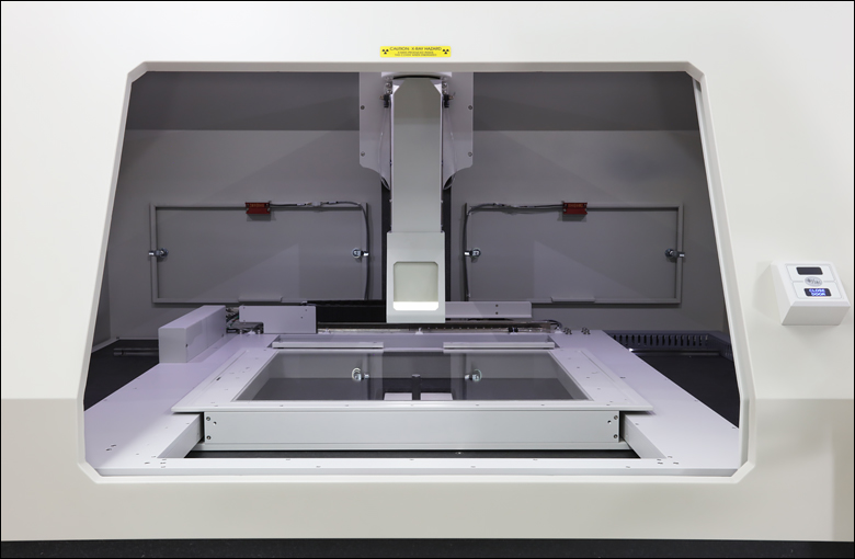
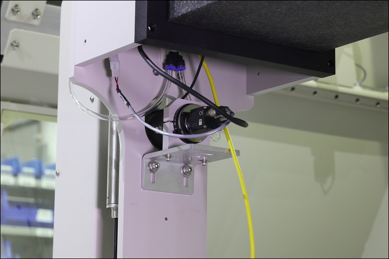
Click to Enlarge
Interior View of XA712 X-Ray Measurement System
Each motor axis and associated encoder is bonded directly onto the granite to create a system that is extremely accurate, stable, and resistant to environmental factors.
The stage uses a combination of air bearings and mechanical bearings to position the stage. The mechanical bearings, consisting of a rail and motor for each axis, provide rigid orthogonality as the stage translates over its full range. Air bearings will not wear, do not require lubrication, and do not generate any particulates during use and thus will require less long-term maintenance. Air bearings are not recommended for unclean environments where dust, dirt, debris, or other contaminants may be present. They will also require a source of clean, pressurized air or nitrogen. It is recommended to lubricate the mechanical bearings and rails periodically.
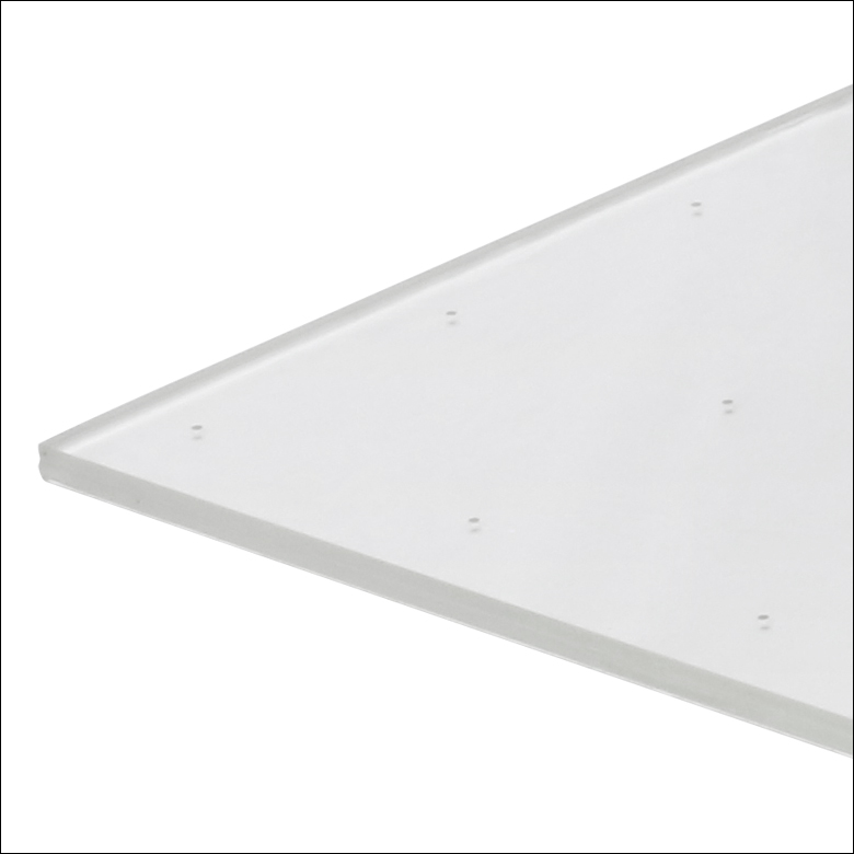
The acrylic moving stage platform offers very high X-ray transmission. An optional hinged platen is available to secure items and press the sample flat on the stage. See the Accessories tab for more information.
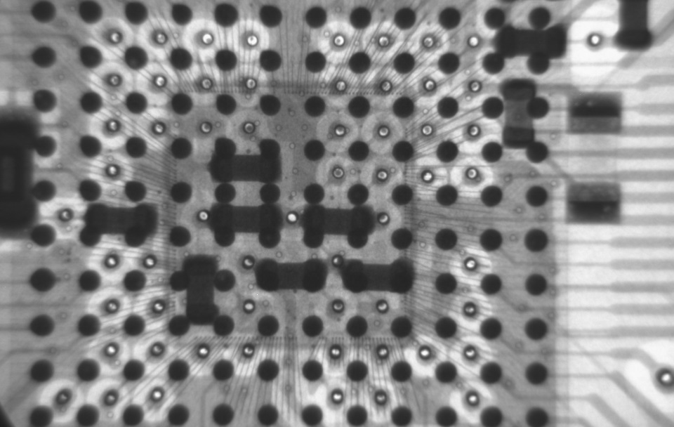
Click to Enlarge
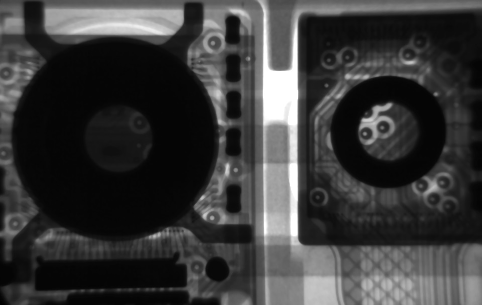
X-Ray Image of a Microchip taken using the InnerVision X-Ray Measurement System
(20 mm Diagonal FOV)
Optical System
The microfocus X-ray source has a Ø5 µm spot size with 4 W of electrical power (maximum 8 W electrical) and a 20 kV to 90 kV voltage range. This can easily penetrate common circuit board materials such as copper and fiberglass up to 0.5" thick, in addition to a variety of plastics and composites with lower X-ray scattering. The source's sealed-tube design is extremely reliable and provides a long system uptime with simple maintenance.
The X-ray source performs an automatic warm-up cycle each time the system is turned on. The routine begins when the X-RAY ENABLE key switch is turned.
The X-ray collection path is cantilevered with granite support over the transport. This collection tube includes a radiation shield and a 1.5 MP flat panel detector to collect, process, and record the signal transmitted through the sample. The configuration of elements results in a 20 mm field of view.
Click for Details
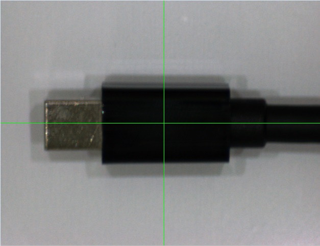
Spotter Camera
A 1.3 MP spotter camera, shown to the left, collects a small portion of visible light that is picked off from the X-ray optical path to provide real-time positioning information. This allows the operator to view the surface features of the sample side-by-side with the corresponding internal features.
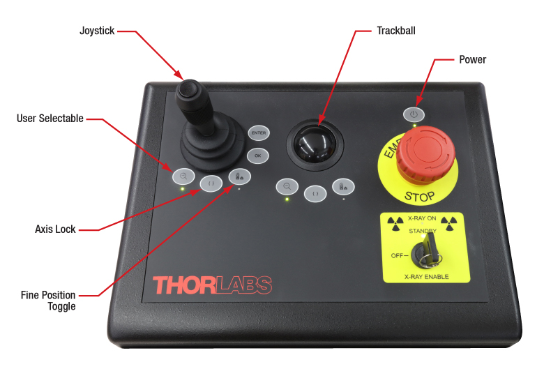
Ergonomic Workstation
Each InnerVision system includes a workstation that can be rotated or vertically adjusted for most operator heights. The workstation includes a 24" touchscreen monitor, keyboard, mouse, and control panel. The control panel, shown to the right, includes a joystick and trackball to manually position the stage, a key switch to enable the X-ray source, an emergency stop switch, a power button to turn the entire system on or off, two sets of three buttons to configure the actions of the joystick or trackball, and Enter/OK buttons for measurement actions.
Click for Details
X-Ray System Control Panel
Joystick and Trackball
The joystick and trackball can both be used at any time to control the motion of the stage. The preferred means of control is up to the user; however, the trackball is designed to minimize the signal delay between its movement and the system's response, allowing operators to have a high level of precise control over their actions.
Control Buttons
A set of three equivalent control buttons are included under both the joystick and trackball. The function of the left button can be selected from a list by the user. The center button is the axis lock, which toggles between single-axis linear motions and free, two-dimensional motion. The right button is the fine position toggle, which allows for small movements of the stage by reducing the responsivity of the joystick.
Emergency Stop
This button will cut power to the entire machine and can be used in the event of an emergency.
Interlock System
The interlock system helps to ensure safety and can be connected to an external interlock system by the user.
Exploring the Options?Thorlabs' X-Ray Metrology Systems are customized to meet the demanding needs of your application. If you do not see a product or specification that you require or you are looking for assistance customizing our system, please contact me. Our Measurement Systems Team is happy to help and can provide system recommendations based on your needs. |
Ike Jariel General Manager Thorlabs Measurement Systems |
| Base Item # | XA712 | XA1272 | |
|---|---|---|---|
| XY Control | |||
| Stage Bearings | Air and Mechanical | ||
| Stage Motors | Linear | ||
| Measurement (Travel) Range | 710 mm x 660 mm (28" x 24") | 1270 mm x 915 mm (50" x 36") | |
| U95 Accuracya |
(5.0 + L/200) µm | ||
| Velocity | 500 mm/s | ||
| X-Ray Source | |||
| Type | Sealed Tube with Integrated Power Supply | ||
| Spot Size | Ø5 µm at 4 W | ||
| Full Exit Angle |
39° | ||
| Voltage Range | 20 - 90 kV | ||
| Current Range | 10 - 200 µA | ||
| Max Electrical Power | 8 W | ||
| Electron Beam Power | 8 W (Max) | ||
| Focus-to-Object Distance (FOD) | 9.5 mm | ||
| Flat Panel Detector | |||
| Sensor | CMOS | ||
| Resolution | 1.5 MP | ||
| Pixels (H x V) | 1032 x 1548 | ||
| Frame Rate | 30 fps | ||
| Field of View (FOV) | 20 mm Diagonal | ||
| Scintillator Material | Gd2O2S | ||
| Dynamic Range | 3000:1 | ||
| Digitization | 14 Bits | ||
| Unit Dimensions | |||
| Typical Unit Dimensions |  |
 |
|
| Rear Clearance | Allow Approximately 500 mm (18") for Servicing | ||
| Approximate System Weight (Uncrated / Crated) |
2600 kg (5700 lbs) / 2760 kg (6050 lbs) | 5443 kg (12 000 lbs) / 5683 kg (12 550 lbs) | |
| General | |||
| Radiation Leakage (5 cm from Any Surface) |
0.3 mR/hr Maximum | ||
| Operating Temperature | Range | 20 ± 0.5 °C (67° - 69 °F) | |
| Rate | 0.25 °C/hr (0.5 °F/hr) | ||
| Relative Humidity (Non-Condensing) | 30% - 80% | ||
| Line Voltage | 115 / 220 VAC, 50 / 60 Hz, Single Phase, 1.0 kW | ||
| Air Supply (For Stage Bearings) | Velocity | 85 L/m (3 CFM) Dry Air | |
| Pressure | 7 - 8.25 Bar (100 - 120 PSI) | ||
Click for Details
Calibration Grid
Click to Enlarge
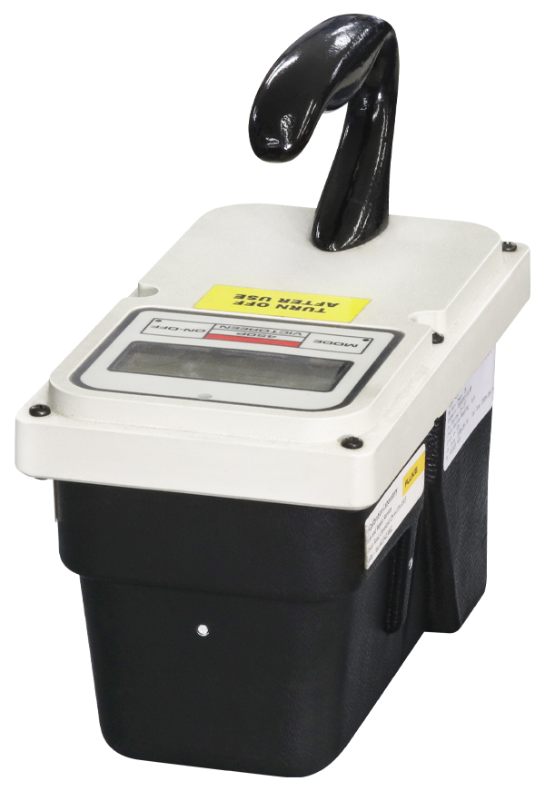
Radiation Survey Meter
The base systems can be upgraded to include one or more of the following add-ons.
Hinged Polycarbonate Platen
A pneumatic, hinged polycarbonate platen can be added to any XY stage to secure and flatten objects or circuit boards up to 0.25" (6.4 mm) thick. The platen can be configured to open automatically as part of a software routine, or when the glass panel is opened manually.
Radiation Survey Meter
A radiation meter is available to periodically audit the system for radiation leakage; this acts as a secondary safety measure to the shielding and safety interlocks that are included with the base system. The meter readout is in units of microroentgens per hour (µR/hr). Please note that radiation leakage can occur at any location on the machine and not necessarily an opening or seam; the entire machine should be audited for leakage according to local regulations.
X-Ray Calibration Grid
A precision grid permits user certification and recalibration of the accuracy and orthogonality of the X-ray system. The grid is modified with X-ray-capable metal targets that are certified traceable to NIST. Grids are available for either size of the X-ray system.
Spare Parts Package
The spare parts package, included with each system purchase, contains a selection of replacement parts matching the specific configuration of the machine. The parts included are components that maintain calibration or commonly need replacement. Having the parts on hand can greatly reduce the time required to get a machine back online in the event of a failure.
Ike Jariel
General Manager
Thorlabs Measurement Systems
Exploring the Options?
Thorlabs' X-Ray Measurement Systems are customized to meet the demanding needs of your application. If you do not see a product or specification that you require or you are looking for assistance selecting a system, please contact me. Our Measurement Systems Team is happy to help and can provide system recommendations based on your needs.
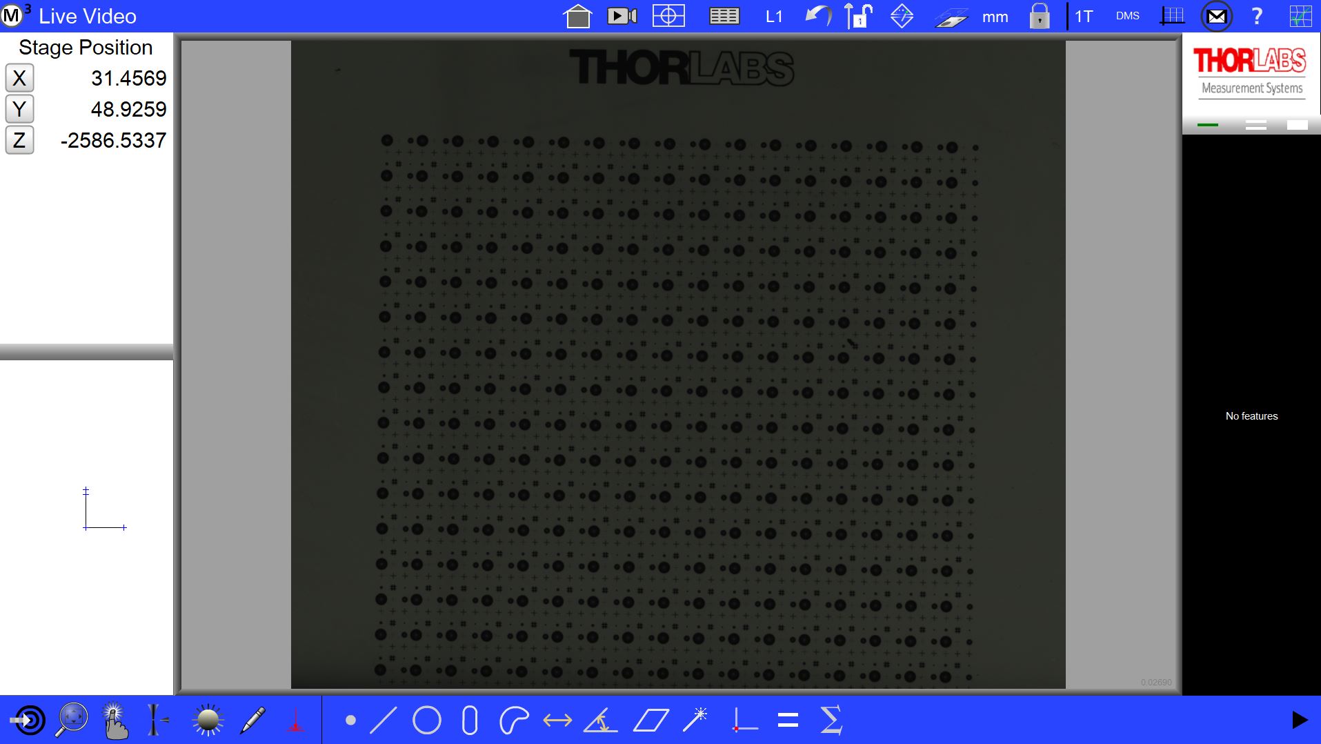
MetLogix® M3 Metrology Control Package
The included software package offers video edge detection to measure and calculate radii, diameters, distances, and angles as well as enable auto-alignment of parts. Unit conversions and nonlinear error corrections are standard. The software includes user programming and tolerance reporting, calculation of complex features, and context-sensitive help screens on an LCD display.
Features
- Program custom routines that control movement, lighting, fixtures, and more.
- The Microsoft Windows® environment is used with on-line help to ease training.
- Programs can be automatically created from CAD data or by recording steps while manually measuring a part.
- Enhanced video edge detection (VED) for selective feature measurement.
- Versatile video edge detection tools such as linewidth, circle, center-of-mass, and buffer that speed the measuring process.
- The system reports position and size of features, allowing optimization of the user’s fabrication process.
- Tolerances to Cartesian, as well as True Position, LMC, and MMC are provided.
| Posted Comments: | |
| No Comments Posted |