 Products Home / Fiber Components / Fused Fiber Optic Couplers / Splitters / 1x16 Single Mode Fiber Optic Splitters
1x16 Single Mode Fiber Optic Splitters

- 1310 / 1550 nm Dual-Window Planar Splitters
- Split Input Evenly into 16 Ports
- 2.0 mm Narrow Key FC/PC or FC/APC Connectors
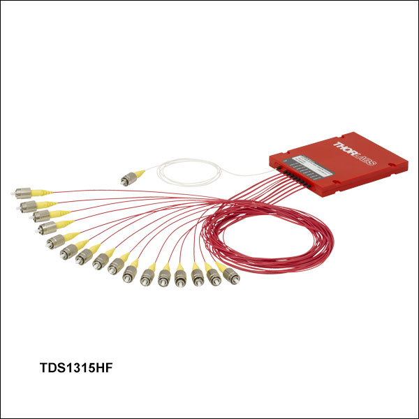
TDS1315HF
FC/PC Connectors
TDS1315HA
FC/APC Connectors
Use for Splitting Signals


Please Wait
Click to Enlarge
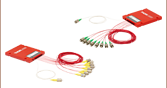
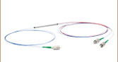
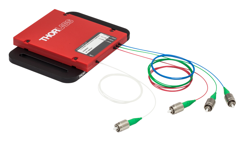
1x16 Wideband Single Mode PLC Splitter Mounted on FCQB Base (Available Below)
Features
- Split Input Signal Evenly into 16 Output Ports
- ±40 nm Bandwidth Around Each Center Wavelength
- 2.0 mm Narrow Key FC/PC or FC/APC Connectors
- 0.8 m Long Fiber Leads with a Tolerance of +0.075 m / -0.0 m
- Individual Test Reports Available for Each Splitter; Click Here for Sample Test Report
- Mount to an Optical Table with the FCQB Mounting Base (Available Below)
Thorlabs' Single Mode 1x16 Fiber Optic Planar Lightwave Circuit (PLC) Splitters allow a user to split a single input signal evenly into 16 output signals, which is ideal for passive optical networks (PON) and other high-channel-count applications. In contrast to fused fiber couplers, where light is coupled from one fiber core to the other, these devices operate as a continuous waveguide that splits the propagating signals. Refer to the 1x16 Splitter Tutorial tab for additional information. Each splitter features a ±40 nm bandwidth around both 1310 nm and 1550 nm center wavelengths and can support a max power of 300 mW when terminated. They cannot be used in reverse to combine light sources together into one output port.
 ) next to the Item # and entering your device's serial number under "Download Serial Item Data." If your device was provided with a paper copy of the test results and you prefer an electronic version, please contact Tech Support.
Thorlabs provides an individual test report for each device that includes coupling ratio and insertion loss at both 1310 nm and 1550 nm for each of the 16 output ports; click here for a sample. Each single mode splitter is contained in a compact 100 mm x 80 mm x 10 mm housing that includes four sets of through holes for mounting the device to our FCQB mounting base (available separately below). These splitters feature a labeled red housing and 0.8 m fiber leads jacketed using Ø900 µm Hytrel®* tubing. Devices are offered from stock with 2.0 mm narrow key FC/PC or FC/APC connectors.
Custom and OEM Fiber Splitters
Our splitters are produced on-site in our North American manufacturing facilities and our design team is able to deliver custom solutions in as little as three weeks. Custom splitter configurations with other wavelengths, fiber types, coupling ratios, port configurations, or housing options are available, and each custom splitter includes an individualized test report. Please contact Tech Sales for inquiries or to discuss your application.
*Hytrel® is a registered trademark of DuPont Polymers, Inc.
1x16 Fiber Optic PLC Splitter Definitions
This tab provides a brief explanation of how we determine several key specifications for our 1x16 planar waveguide splitters. These devices are fabricated waveguide splitters that split the input signal evenly among 16 outputs. These splitters are not recommended for light combining applications and should only be used to split light. For combining light of different wavelengths, Thorlabs offers a line of wavelength division multiplexers (WDMs).
Excess Loss
Excess loss in dB is determined by the ratio of the total input power to the total output power:
Pinput is the input power, and the Pport is the output power at each port; when summed across all ports, this represents the total output power. All powers are expressed in mW.
Insertion Loss
The insertion loss is defined as the ratio of the input power to the output power for a given port of the splitter. Insertion loss is always specified in decibels (dB). It is generally defined using the equation below:
where Pin and Pout are the input and output powers (in mW). For our 1x16 PLC splitters, the insertion loss specification is provided for each output port. To define the insertion loss for a specific output (e.g., port 1 or port 2), the equation is rewritten as:
Insertion loss inherently includes both coupling (e.g., light transferred to the other output legs) and excess loss (e.g., light lost from the splitter) effects. The maximum allowed insertion loss for each output is specified. Because the insertion loss in each output is correlated to light coupled to the other outputs, no splitter will ever have the maximum insertion loss in all outputs simultaneously.
Calculating Insertion Loss using Power Expressed in dBm
Insertion loss can also be easily calculated with the power expressed in units of dBm. The equation below shows the relationship between power expressed in mW and dBm:
Then, the insertion loss in dB can be calculated as follows:

Optical Return Loss (ORL)
Optical return loss (ORL) is the fraction of light that is reflected back into the input port of the component.
Coupling Ratio
Insertion loss (in dB) is the ratio of the input power to the output power from each leg of the splitter as a function of wavelength. It captures both the coupling ratio and the excess loss. The coupling ratio is calculated from the measured insertion loss. Coupling ratio (in %) is the ratio of the optical power from each output port to the sum of the total power of all output ports as a function of wavelength. It is not impacted by spectral features such as the water absorption region because all output legs are affected equally.
Uniformity
The uniformity is also calculated from the measured insertion loss. Uniformity is the variation (in dB) of the insertion loss over the bandwidth as a function of wavelength. It is a measure of how evenly the insertion loss is distributed over the spectral range. The uniformity is defined as the difference between the insertion loss in one output leg at a given wavelength and the highest or lowest value of insertion loss over the specified wavelength range in that same output leg.
| Quick Links |
|---|
| Damage at the Air / Glass Interface |
| Intrinsic Damage Threshold |
| Preparation and Handling of Optical Fibers |
Laser-Induced Damage in Silica Optical Fibers
The following tutorial details damage mechanisms relevant to unterminated (bare) fiber, terminated optical fiber, and other fiber components from laser light sources. These mechanisms include damage that occurs at the air / glass interface (when free-space coupling or when using connectors) and in the optical fiber itself. A fiber component, such as a bare fiber, patch cable, or fused coupler, may have multiple potential avenues for damage (e.g., connectors, fiber end faces, and the device itself). The maximum power that a fiber can handle will always be limited by the lowest limit of any of these damage mechanisms.
While the damage threshold can be estimated using scaling relations and general rules, absolute damage thresholds in optical fibers are very application dependent and user specific. Users can use this guide to estimate a safe power level that minimizes the risk of damage. Following all appropriate preparation and handling guidelines, users should be able to operate a fiber component up to the specified maximum power level; if no maximum is specified for a component, users should abide by the "practical safe level" described below for safe operation of the component. Factors that can reduce power handling and cause damage to a fiber component include, but are not limited to, misalignment during fiber coupling, contamination of the fiber end face, or imperfections in the fiber itself. For further discussion about an optical fiber’s power handling abilities for a specific application, please contact Thorlabs’ Tech Support.
Damage at the Air / Glass Interface
There are several potential damage mechanisms that can occur at the air / glass interface. Light is incident on this interface when free-space coupling or when two fibers are mated using optical connectors. High-intensity light can damage the end face leading to reduced power handling and permanent damage to the fiber. For fibers terminated with optical connectors where the connectors are fixed to the fiber ends using epoxy, the heat generated by high-intensity light can burn the epoxy and leave residues on the fiber facet directly in the beam path.
| Table 36C Estimated Optical Power Densities on Air / Glass Interfacea | ||
|---|---|---|
| Type | Theoretical Damage Thresholdb | Practical Safe Levelc |
| CW (Average Power) |
~1 MW/cm2 | ~250 kW/cm2 |
| 10 ns Pulsed (Peak Power) |
~5 GW/cm2 | ~1 GW/cm2 |
Damage Mechanisms on the Bare Fiber End Face
Damage mechanisms on a fiber end face can be modeled similarly to bulk optics, and industry-standard damage thresholds for UV Fused Silica substrates can be applied to silica-based fiber. However, unlike bulk optics, the relevant surface areas and beam diameters involved at the air / glass interface of an optical fiber are very small, particularly for coupling into single mode (SM) fiber. therefore, for a given power density, the power incident on the fiber needs to be lower for a smaller beam diameter.
Table 36C lists two thresholds for optical power densities: a theoretical damage threshold and a "practical safe level". In general, the theoretical damage threshold represents the estimated maximum power density that can be incident on the fiber end face without risking damage with very good fiber end face and coupling conditions. The "practical safe level" power density represents minimal risk of fiber damage. Operating a fiber or component beyond the practical safe level is possible, but users must follow the appropriate handling instructions and verify performance at low powers prior to use.
Calculating the Effective Area for Single Mode Fibers
The effective area for single mode (SM) fiber is defined by the mode field diameter (MFD), which is the cross-sectional area through which light propagates in the fiber; this area includes the fiber core and also a portion of the cladding. To achieve good efficiency when coupling into a single mode fiber, the diameter of the input beam must match the MFD of the fiber.
As an example, SM400 single mode fiber has a mode field diameter (MFD) of ~Ø3 µm operating at 400 nm, while the MFD for SMF-28 Ultra single mode fiber operating at 1550 nm is Ø10.5 µm. The effective area for these fibers can be calculated as follows:
SM400 Fiber: Area = Pi x (MFD/2)2 = Pi x (1.5 µm)2 = 7.07 µm2 = 7.07 x 10⁻⁸ cm2
SMF-28 Ultra Fiber: Area = Pi x (MFD/2)2 = Pi x (5.25 µm)2 = 86.6 µm2 = 8.66 x 10⁻⁷ cm2
To estimate the power level that a fiber facet can handle, the power density is multiplied by the effective area. Please note that this calculation assumes a uniform intensity profile, but most laser beams exhibit a Gaussian-like shape within single mode fiber, resulting in a higher power density at the center of the beam compared to the edges. Therefore, these calculations will slightly overestimate the power corresponding to the damage threshold or the practical safe level. Using the estimated power densities assuming a CW light source, we can determine the corresponding power levels as:
SM400 Fiber: 7.07 x 10⁻⁸ cm2 x 1 MW/cm2 = 7.1 x 10⁻⁸ MW = 71 mW (Theoretical Damage Threshold)
7.07 x 10⁻⁸ cm2 x 250 kW/cm2 = 1.8 x 10⁻⁵ kW = 18 mW (Practical Safe Level)
SMF-28 Ultra Fiber: 8.66 x 10⁻⁷ cm2 x 1 MW/cm2 = 8.7 x 10⁻⁷ MW = 870 mW (Theoretical Damage Threshold)
8.66 x 10⁻⁷ cm2 x 250 kW/cm2 = 2.1 x 10⁻⁴ kW = 210 mW (Practical Safe Level)
Effective Area of Multimode Fibers
The effective area of a multimode (MM) fiber is defined by the core diameter, which is typically far larger than the MFD of an SM fiber. For optimal coupling, Thorlabs recommends focusing a beam to a spot roughly 70 - 80% of the core diameter. The larger effective area of MM fibers lowers the power density on the fiber end face, allowing higher optical powers (typically on the order of kilowatts) to be coupled into multimode fiber without damage.
Damage Mechanisms Related to Ferrule / Connector Termination
 Click to Enlarge
Figure 36D Plot showing approximate input power that can be incident on a single mode silica optical fiber with a termination. Each line shows the estimated power level due to a specific damage mechanism. The maximum power handling is limited by the lowest power level from all relevant damage mechanisms (indicated by a solid line).
Fibers terminated with optical connectors have additional power handling considerations. Fiber is typically terminated using epoxy to bond the fiber to a ceramic or steel ferrule. When light is coupled into the fiber through a connector, light that does not enter the core and propagate down the fiber is scattered into the outer layers of the fiber, into the ferrule, and the epoxy used to hold the fiber in the ferrule. If the light is intense enough, it can burn the epoxy, causing it to vaporize and deposit a residue on the face of the connector. This results in localized absorption sites on the fiber end face that reduce coupling efficiency and increase scattering, causing further damage.
For several reasons, epoxy-related damage is dependent on the wavelength. In general, light scatters more strongly at short wavelengths than at longer wavelengths. Misalignment when coupling is also more likely due to the small MFD of short-wavelength SM fiber that also produces more scattered light.
To minimize the risk of burning the epoxy, fiber connectors can be constructed to have an epoxy-free air gap between the optical fiber and ferrule near the fiber end face. Our high-power multimode fiber patch cables use connectors with this design feature.
Determining Power Handling with Multiple Damage Mechanisms
When fiber cables or components have multiple avenues for damage (e.g., fiber patch cables), the maximum power handling is always limited by the lowest damage threshold that is relevant to the fiber component. In general, this represents the highest input power that can be incident on the patch cable end face and not the coupled output power.
As an illustrative example, Figure 36D shows an estimate of the power handling limitations of a single mode fiber patch cable due to damage to the fiber end face and damage via an optical connector. The total input power handling of a terminated fiber at a given wavelength is limited by the lower of the two limitations at any given wavelength (indicated by the solid lines). A single mode fiber operating at around 488 nm is primarily limited by damage to the fiber end face (blue solid line), but fibers operating at 1550 nm are limited by damage to the optical connector (red solid line).
In the case of a multimode fiber, the effective mode area is defined by the core diameter, which is larger than the effective mode area for SM fiber. This results in a lower power density on the fiber end face and allows higher optical powers (on the order of kilowatts) to be coupled into the fiber without damage (not shown in graph). However, the damage limit of the ferrule / connector termination remains unchanged and as a result, the maximum power handling for a multimode fiber is limited by the ferrule and connector termination.
Please note that these are rough estimates of power levels where damage is very unlikely with proper handling and alignment procedures. It is worth noting that optical fibers are frequently used at power levels above those described here. However, these applications typically require expert users and testing at lower powers first to minimize risk of damage. Even still, optical fiber components should be considered a consumable lab supply if used at high power levels.
Intrinsic Damage Threshold
In addition to damage mechanisms at the air / glass interface, optical fibers also display power handling limitations due to damage mechanisms within the optical fiber itself. These limitations will affect all fiber components as they are intrinsic to the fiber itself. Two categories of damage within the fiber are damage from bend losses and damage from photodarkening.
Bend Losses
Bend losses occur when a fiber is bent to a point where light traveling in the core is incident on the core/cladding interface at an angle higher than the critical angle, making total internal reflection impossible. Under these circumstances, light escapes the fiber, often in a localized area. The light escaping the fiber typically has a high power density, which burns the fiber coating as well as any surrounding furcation tubing.
A special category of optical fiber, called double-clad fiber, can reduce the risk of bend-loss damage by allowing the fiber’s cladding (2nd layer) to also function as a waveguide in addition to the core. By making the critical angle of the cladding/coating interface higher than the critical angle of the core/clad interface, light that escapes the core is loosely confined within the cladding. It will then leak out over a distance of centimeters or meters instead of at one localized spot within the fiber, minimizing the risk of damage. Thorlabs manufactures and sells 0.22 NA double-clad multimode fiber, which boasts very high, megawatt range power handling.
Photodarkening
A second damage mechanism, called photodarkening or solarization, can occur in fibers used with ultraviolet or short-wavelength visible light, particularly those with germanium-doped cores. Fibers used at these wavelengths will experience increased attenuation over time. The mechanism that causes photodarkening is largely unknown, but several fiber designs have been developed to mitigate it. For example, fibers with a very low hydroxyl ion (OH) content have been found to resist photodarkening and using other dopants, such as fluorine, can also reduce photodarkening.
Even with the above strategies in place, all fibers eventually experience photodarkening when used with UV or short-wavelength light, and thus, fibers used at these wavelengths should be considered consumables.
Preparation and Handling of Optical Fibers
General Cleaning and Operation Guidelines
These general cleaning and operation guidelines are recommended for all fiber optic products. Users should still follow specific guidelines for an individual product as outlined in the support documentation or manual. Damage threshold calculations only apply when all appropriate cleaning and handling procedures are followed.
-
All light sources should be turned off prior to installing or integrating optical fibers (terminated or bare). This ensures that focused beams of light are not incident on fragile parts of the connector or fiber, which can possibly cause damage.
-
The power-handling capability of an optical fiber is directly linked to the quality of the fiber/connector end face. Always inspect the fiber end prior to connecting the fiber to an optical system. The fiber end face should be clean and clear of dirt and other contaminants that can cause scattering of coupled light. Bare fiber should be cleaved prior to use and users should inspect the fiber end to ensure a good quality cleave is achieved.
-
If an optical fiber is to be spliced into the optical system, users should first verify that the splice is of good quality at a low optical power prior to high-power use. Poor splice quality may increase light scattering at the splice interface, which can be a source of fiber damage.
-
Users should use low power when aligning the system and optimizing coupling; this minimizes exposure of other parts of the fiber (other than the core) to light. Damage from scattered light can occur if a high power beam is focused on the cladding, coating, or connector.
Tips for Using Fiber at Higher Optical Power
Optical fibers and fiber components should generally be operated within safe power level limits, but under ideal conditions (very good optical alignment and very clean optical end faces), the power handling of a fiber component may be increased. Users must verify the performance and stability of a fiber component within their system prior to increasing input or output power and follow all necessary safety and operation instructions. The tips below are useful suggestions when considering increasing optical power in an optical fiber or component.
-
Splicing a fiber component into a system using a fiber splicer can increase power handling as it minimizes possibility of air/fiber interface damage. Users should follow all appropriate guidelines to prepare and make a high-quality fiber splice. Poor splices can lead to scattering or regions of highly localized heat at the splice interface that can damage the fiber.
-
After connecting the fiber or component, the system should be tested and aligned using a light source at low power. The system power can be ramped up slowly to the desired output power while periodically verifying all components are properly aligned and that coupling efficiency is not changing with respect to optical launch power.
-
Bend losses that result from sharply bending a fiber can cause light to leak from the fiber in the stressed area. When operating at high power, the localized heating that can occur when a large amount of light escapes a small localized area (the stressed region) can damage the fiber. Avoid disturbing or accidently bending fibers during operation to minimize bend losses.
-
Users should always choose the appropriate optical fiber for a given application. For example, large-mode-area fibers are a good alternative to standard single mode fibers in high-power applications as they provide good beam quality with a larger MFD, decreasing the power density on the air/fiber interface.
-
Step-index silica single mode fibers are normally not used for ultraviolet light or high-peak-power pulsed applications due to the high spatial power densities associated with these applications.
| Posted Comments: | |
| No Comments Posted |

 Zoom
Zoom
 Zoom
Zoom
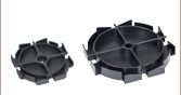
Click to Enlarge
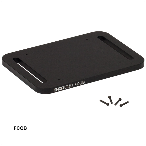
The FCQB base is designed for the red package used to house Thorlabs' WDMs, 1x4 couplers, and splitters, as shown above.
- Mounting Base for:
- 3-Wavelength WDMs
- 1x4 Couplers
- 1x4, 1x8, or 1x16 Splitters
- Four M2 Taps for Mounting Fiber Optic Component Housing
- 2.25" Long Clearance Slots Accepts 1/4"-20 (M6) Screws
- Four M2 Mounting Screws Included
The FCQB mounting base provides two 2.25" long clearance slots for 1/4" (M6) cap screws to secure the base to an optical table or other tapped surface. The two clearance slots are located 4" (101.6 mm) apart at opposite edges of the mounting base. Four M2 taps between the clearance slots are positioned to align with the through holes in Thorlabs' 3-Wavelength Wavelength Division Multiplexers (WDMs), 1x4 SM Couplers, 1x4 PM Splitters, 1x8 SM Splitters, 1x8 PM Splitters, 1x16 SM Splitters, or 1x16 PM Splitters. Four M2 screws are included.