 Products Home / Optomechanical Components / Optical Cage Systems / Fiber Coupling and Spatial Filter Systems
Fiber Coupling and Spatial Filter Systems
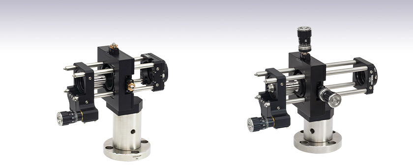
- Free Space Fiber Launch System with Submicron XY Translator
- Spatial Filter System Produces "Clean" Gaussian Beams
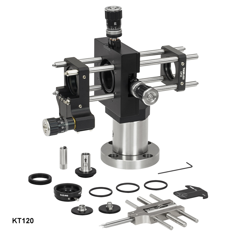
KT120
Free-Space
Fiber Coupler
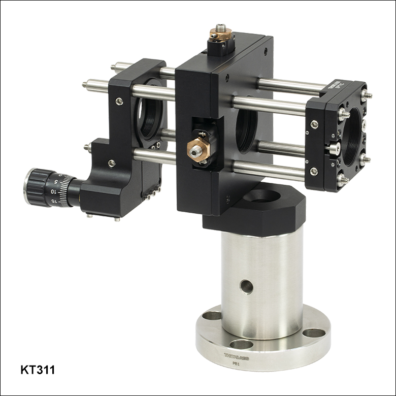
KT311
Spatial Filter System


Please Wait
| Recommended Focusing Opticsa | |
|---|---|
| Item # | Description |
| C230TMD-A | 350 - 700 nm, f = 4.51 mm, NA = 0.55 Aspheric Lens |
| C230TMD-B | 600 - 1050 nm, f = 4.51 mm, NA = 0.55 Aspheric Lens |
| C230TMD-C | 1050 - 1700 nm, f = 4.51 mm, NA = 0.55 Aspheric Lens |
Features
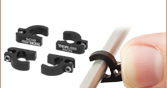
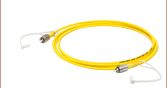
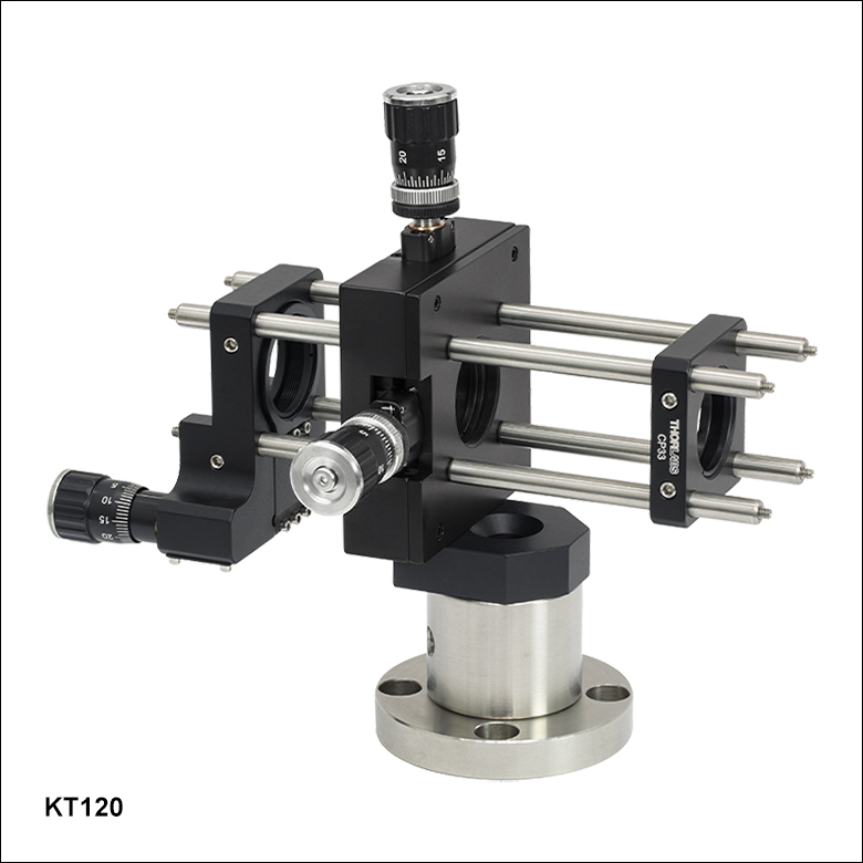
- KT120(/M) Fiber Coupler Accepts FC or SMA Fiber Cables
- High-Precision Differential Adjusters Included with KT120(/M) Provide Submicron Translation
- KT311(/M) Spatial Filter Directly Compatible with Ø9 mm Aspheric Lens Housings
- Easy-to-Follow Instructions and Alignment Tools
Fiber Launch Systems
Thorlabs' KT120(/M) fiber launch system couples free-space laser beams into fiber optic cables. This system, which can be used with single or multimode fiber, is equipped with high-precision differential adjusters capable of submicron translation.
This fiber launch system only includes optomechanical components (see the Components tab for a complete list of components). The table to the upper right lists the recommended optics for focusing collimated light into an output fiber connected to the KT120(/M) system. Note that to reach the best coupling performance into a multimode fiber, the numerical aperture of the lens should match that of the fiber. Similarly, for optimized coupling into a single mode fiber the spot size of the focused beam must be less than the mode-field diameter of the fiber.
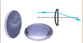
Spatial Filter Systems
Many applications, such as holography, require a beam with uniform intensity. The KT311(/M) spatial filter is ideal for producing a clean, spatially uniform, Gaussian beam. The input of this system consists of a Z-axis translator, which can house a diffraction-limted aspheric lens. This aspheric lens focuses the beam through a pinhole, which can be mounted in the XY translator. The output consists of a Ø1" cage mount, which holds and centers a collimating optic.
This filter system only includes optomechanical components (see the Components tab for a complete list of components). The aspheric lens, collimating optics, and pinhole must be purchased separately. Please refer to the Tutorial tab for more information on choosing the appropriate optics and pinhole for your application.
| KT120 | KT120/M | Description | Qty. | |
|---|---|---|---|---|
| CP33 | CP33/M | SM1-Threaded 30 mm Cage Plate | 1 | |
| CPA1 | 30 mm Cage System Alignment Plate | 1 | ||
| E09RMS | Extended RMS to M9 x 0.5 Adapter | 1 | ||
| ER2 | Cage Assembly Rod, 2" Long | 4 | ||
| ER3 | Cage Assembly Rod, 3" Long | 4 | ||
| MA2 | MA2/M | Ø1.5" Post Mounting Adapter | 1 | |
| P1.5 | P30/M | Ø1.5" Mounting Post | 1 | |
| PB1 | Mounting Post Base | 1 | ||
| SM1A3 | Adapter with External SM1 Threads and Internal RMS Threads |
1 | ||
| SM1D12 | SM1 Lever-Actuated Iris Diaphragm | 1 | ||
| SM1FC | FC/PC Fiber Adapter Plate | 1 | ||
| SM1RR | SM1 Retaining Ring | 3 | ||
| SM1ZA | Z-Axis Translation Mount | 1 | ||
| SPW301 | Spanner Wrench for a M9 x 0.5 Optics Housing | 1 | ||
| SPW801 | Adjustable Spanner Wrench | 1 | ||
| ST1XY-D | ST1XY-D/M | XY Translator with Differential Drives | 1 | |
| SM1SMA | SMA Fiber Adapter Plate | 1 | ||
| - | 5/64" (2.0 mm) Hex Keya | 1 | ||

| KT311 | KT311/M | Description | Qty. |
|---|---|---|---|
| CPA1 | 30 mm Cage System Alignment Plate | 1 | |
| E09RMS | Extended RMS to M9 x 0.5 Adapter | 1 | |
| ER2 | Cage Assembly Rod, 2" Long | 8 | |
| MA2 | MA2/M | Ø1.5" Post Mounting Adapter | 1 |
| P2 | P50/M | Ø1.5" Mounting Post | 1 |
| PB1 | Mounting Post Base | 1 | |
| SM1L03 | SM1 Lens Tube, 0.3" Thread Depth | 1 | |
| SM1A3 | Adapter with External SM1 Threads and Internal RMS Threads |
1 | |
| SM1RR | SM1 Retaining Ring | 3 | |
| SM1ZA | Z-Axis Translation Mount | 1 | |
| SPT1C | SPT1C/M | Coarse ±1 mm XY Slip Plate Positioner | 1 |
| SPW301 | Spanner Wrench for a M9 x 0.5 Optics Housing | 1 | |
| SPW801 | Adjustable Spanner Wrench | 1 | |
| ST1XY-A | ST1XY-A/M | XY Translator with 100 TPI Drives | 1 |
| - | 5/64" (2.0 mm) Hex Keya | 1 | |
Principles of Spatial Filters
For many applications, such as holography, spatial intensity variations in the laser beam are unacceptable. Our KT311(/M) spatial filter system is ideal for producing clean Gaussian beams.
Figure 1: Spatial Filter System
The input Gaussian beam has spatially varying intensity "noise". When a beam is focused by an aspheric lens, the input beam is transformed into a central Gaussian spot (on the optical axis) and side fringes, which represent the unwanted "noise" (see Figure 2 below). The radial position of the side fringes is proportional to the spatial frequency of the "noise".
Figure 2
By centering a pinhole on a central Gaussian spot, the "clean" portion of the beam can pass while the "noise" fringes are blocked (see Figure 3 below).
Figure 3
The diffraction-limited spot size at the 99% contour is given by:

where λ = wavelength, ƒ=focal length and r = input beam radius at the 1/e2 point.
Choosing the Correct Optics and Pinhole for Your Spatial Filter System
The correct optics and pinhole for your application depend on the input wavelength, source beam diameter, and desired exit beam diameter.
For example, suppose that you are using a 650 nm diode laser source that has a diameter (1/e2) of 1.2 mm and want your beam exiting the spatial filter system to be about 4.4 mm in diameter. Based on these parameters, the C560TME-B mounted aspheric lens would be an appropriate choice for the input side of spatial filter system because it is designed for use at 650 nm, and its clear aperture measures 5.1 mm, which is large enough to accommodate the entire diameter of the laser source.
The equation for diffraction limited spot size at the 99% contour is given above, and for this example, λ = (650 x 10-9 m), f = 13.86 mm for the C560TM-B, and r = 0.6 mm. Substitution yields
Diffraction-Limited Spot Size (650 nm source, Ø1.2 mm beam)
The pinhole should be chosen so that it is approximately 30% larger than D. If the pinhole is too small, the beam will be clipped, but if it is too large, more than the TEM00 mode will get through the pinhole. Therefore, for this example, the pinhole should ideally be 19.5 microns. Hence, we would recommend the mounted pinhole P20K, which has a pinhole size of 20 μm. Parameters that can be changed to alter the beam waist diameter, and thus the pinhole size required, include changing the input beam diameter and focal length of focusing lens. Decreasing the input beam diameter will increase the beam waist diameter. Using a longer focal length focusing lens will also increase the beam waist diameter.
Finally, we need to choose the optic on the output side of the spatial filter so that the collimated beam's diameter is the desired 4.4 mm. To determine the correct focal length for the lens, consider the following diagram in Figure 4, which is not drawn to scale. From the triangle on the left-hand side, the angle is determined to be approximately 2.48o. Using this same angle for the triangle on the right-hand side, the focal length for the plano-convex lens should be approximately 50 mm.
Figure 4: Beam Expansion Example
For this focal length, we recommend the LA1131-B plano-convex lens [with f = 50 mm at the design wavelength (λ = 633 nm), this is still a good approximation for f at the source wavelength (λ = 650 nm)].
Note: The beam expansion equals the focal length of the output side divided by the focal length of the input side.
For optimal performance, a large-diameter aspheric lens can be used in place of a plano-convex lens if the necessary focal length on the output side is 20 mm (see AL2520-A, AL2520-B, AL2520-C). These lenses are 25 mm in diameter and can be held in place using the supplied SM1RR Retaining Ring.
Click to Enlarge
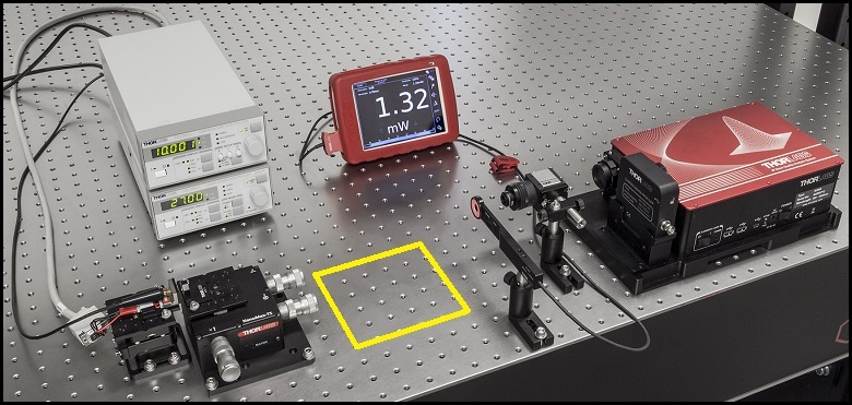
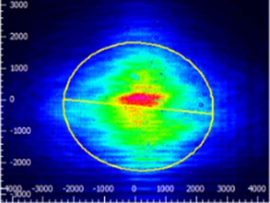
Figure 1: The beam circularization systems were placed in the area of the experimental setup highlighted by the yellow rectangle.

Click to Enlarge
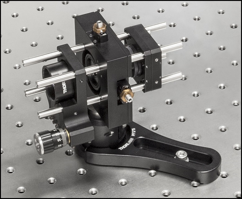
Figure 4: Spatial Filter System
Click to Enlarge
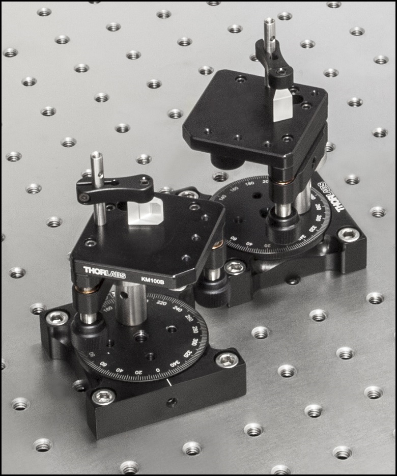
Figure 3: Anamorphic Prism Pair System
Click to Enlarge
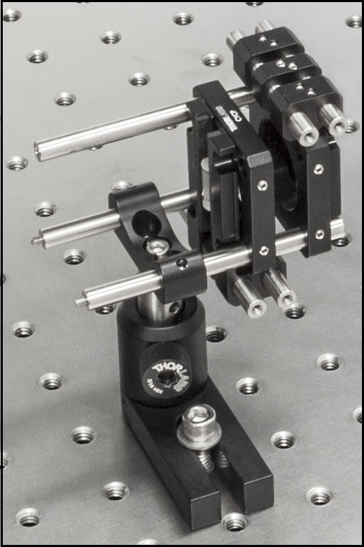
Figure 2: Cylindrical Lens Pair System
Comparison of Circularization Techniques for Elliptical Beams
Edge-emitting laser diodes emit elliptical beams as a consequence of the rectangular cross sections of their emission apertures. The component of the beam corresponding to the narrower dimension of the aperture has a greater divergence angle than the orthogonal beam component. As one component diverges more rapidly than the other, the beam shape is elliptical rather than circular.
Elliptical beam shapes can be undesirable, as the spot size of the focused beam is larger than if the beam were circular, and as larger spot sizes have lower irradiances (power per area). Techniques for circularizing an elliptical beam include those based on a pair of cylindrical lenses, an anamorphic prism pair, or a spatial filter. This work investigated all three approaches. The characteristics of the circularized beams were evaluated by performing M2 measurements, wavefront measurements, and measuring the transmitted power.
While it was demonstrated that each circularization technique improves the circularity of the elliptical input beam, each technique was shown to provide a different balance of circularization, beam quality, and transmitted power. The results of this work, which are documented in this Lab Fact, indicate that an application's specific requirements will determine which is the best circularization technique to choose.
Experimental Design and Setup
The experimental setup is shown in Figure 1. The elliptically-shaped, collimated beam of a temperature-stabilized 670 nm laser diode was input to each of our circularization systems shown in Figures 2 through 4. Collimation results in a low-divergence beam, but it does not affect the beam shape. Each system was based on one of the following:
- LJ1874L2-A and LJ1638L1-A Plano-Convex Convex Cylindrical Lenses (Figure 2)
- PS873-A Unmounted Anamorphic Prism Pair (Figure 3)
- Previous Generation KT310 Spatial Filter System with P5S Ø5 µm Pinhole (Figure 4)
The beam circularization systems, shown to the right, were placed, one at a time, in the vacant spot in the setup highlighted by the yellow rectangle. With this arrangement, it was possible to use the same experimental conditions when evaluating each circularization technique, which allowed the performance of each to be directly compared with the others. This experimental constraint required the use of fixturing that was not optimally compact, as well as the use of an unmounted anamorphic prism pair, instead of a more convenient mounted and pre-aligned anamorphic prism pair.
The characteristics of the beams output by the different circularization systems were evaluated by making measurements using a power meter, a wavefront sensor, and an M2 system. In the image of the experimental setup, all of these systems are shown on the right side of the table for illustrative purposes; they were used one at a time. The power meter was used to determine how much the beam circularization system attenuated the intensity of the input laser beam. The wavefront sensor provided a way to measure the aberrations of the output beam. The M2 system measurement describes the resemblance of the output beam to a Gaussian beam. Ideally, the circularization systems would not attenuate or aberrate the laser beam, and they would output a perfectly Gaussian beam.
Edge-emitting laser diodes also emit astigmatic beams, and it can be desirable to force the displaced focal points of the orthogonal beam components to overlap. Of the three circularization techniques investigated in this work, only the cylindrical lens pair can also compensate for astigmatism. The displacement between the focal spots of the orthogonal beam components were measured for each circularization technique. In the case of the cylindrical lens pair, their configuration was tuned to minimize the astigmatism in the laser beam. The astigmatism was reported as a normalized quantity.
Experimental Results
The experimental results are summarized in the following table, in which the green cells identify the best result in each category. Each circularization approach has its benefits. The best circularization technique for an application is determined by the system’s requirements for beam quality, transmitted optical power, and setup constraints.
Spatial filtering significantly improved the circularity and quality of the beam, but the beam had low transmitted power. The cylindrical lens pair provided a well-circularized beam and balanced circularization and beam quality with transmitted power. In addition, the cylindrical lens pair compensated for much of the beam's astigmatism. The circularity of the beam provided by the anamorphic prism pair compared well to that of the cylindrical lens pair. The beam output from the prisms had better M2 values and less wavefront error than the cylindrical lenses, but the transmitted power was lower.
| Method | Beam Intensity Profile | Circularitya | M2 Values | RMS Wavefront | Transmitted Power | Normalized Astigmatismb |
|---|---|---|---|---|---|---|
| Collimated Source Output (No Circularization Technique) |
 Click to Enlarge Scale in Microns |
0.36 | Y Axis: 1.63 |
0.17 | Not Applicable | 0.67 |
| Cylindrical Lens Pair | 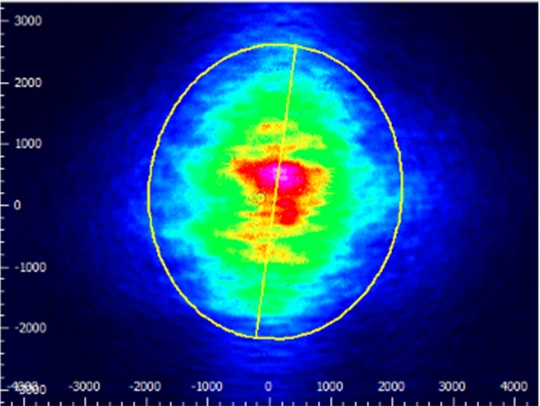 Click to Enlarge Scale in Microns |
0.84 | X Axis: 1.90 Y Axis: 1.93 |
0.30 | 91% | 0.06 |
| Anamorphic Prism Pair |
 Click to Enlarge Scale in Microns |
0.82 | X Axis: 1.60 Y Axis: 1.46 |
0.16 | 80% | 1.25 |
| Spatial Filter |  Click to Enlarge Scale in Microns |
0.93 | X Axis: 1.05 Y Axis: 1.10 |
0.10 | 34% | 0.36 |
Components used in each circularization system were chosen to allow the same experimental setup be used for all experiments. This had the desired effect of allowing the results of all circularization techniques to be directly compared; however, optimizing the setup for a circularization technique could have improved its performance. The mounts used for the collimating lens and the anamorphic prism pair enabled easy manipulation and integration into this experimental system. It is possible that using smaller mounts would improve results by allowing the members of each pair to be more precisely positioned with respect to one another. In addition, using made-to-order cylindrical lenses with customized focal lengths may have improved the results of the cylindrical lens pair circularization system. All results may have been affected by the use of the beam profiler software algorithm to determine the beam radii used in the circularity calculation.
Additional Information
Some information describing selection and configuration procedures for several components used in this experimental work can be accessed by clicking the following hyperlinks:
Cage System Overview
The Cage Assembly System provides a convenient way to construct large optomechanical systems with an established line of precision-machined building blocks designed for high flexibility and accurate alignment.
16 mm, 30 mm, and 60 mm Cage System Standards
Thorlabs offers three standards defined by the center-to-center spacing of the cage assembly rods (see image below). The 16 mm cage, 30 mm cage, and 60 mm cage standards are designed to accommodate Ø1/2", Ø1", and Ø2" optics, respectively. Specialized cage plates that allow smaller optics to be directly inserted into our larger cage systems are also available.
Standard Threads
The flexibility of our Cage Assembly System stems from well-defined mounting and thread standards designed to directly interface with a wide range of specialized products. The three most prevalent thread standards are our SM05 Series (0.535"-40 thread), SM1 Series (1.035"-40 thread), and SM2 Series (2.035"-40 thread), all of which were defined to house the industry's most common optic sizes. Essential building blocks, such as our popular lens tubes, directly interface to these standards.
An example of the standard cage plate measurements determining cage system compatibility.
| Standard Cage System Measurements | |||
|---|---|---|---|
| Cage System | 16 mm | 30 mm | 60 mm |
| Thread Series | SM05 | SM1 | SM2 |
| Rod to Rod Spacing | 16 mm (0.63") | 30 mm (1.18") | 60 mm (2.36") |
| Total Length | 25 mm (0.98") | 41 mm (1.60") | 71.1 mm (2.80") |
| Cage Components | ||
|---|---|---|
| Cage Rods | 16 mm | These rods are used to connect cage plates, optic mounts, and other components in the cage system. The SR Series Cage Rods are compatible with our 16 mm cage systems, while the 30 mm and 60 mm cage systems use ER Series Cage Rods. |
| 30 mm | ||
| 60 mm | ||
| Cage Plates | 16 mm | These serve as the basic building blocks for a cage system. They may have SM-threaded central bores, smooth bores sized for industry standard optics or to accommodate the outer profile of our SM Series Lens Tubes, or specialized bores for other components such as our FiberPorts. |
| 30 mm | ||
| 60 mm | ||
| Optic Mounts | 16 mm | Thorlabs offers fixed, kinematic, rotation, and translation mounts specifically designed for our Cage Systems. |
| 30 mm | ||
| 60 mm | ||
| Cage Cubes | 16 mm | These cubes are useful for housing larger optical components, such as prisms or mirrors, or optics that need to sit at an angle to the beam path, such as beamsplitters. Our cage cubes are available empty or with pre-mounted optics. |
| 30 mm | ||
| 60 mm | ||
| Replacement Setscrews | Replacement setscrews are offered for our 16 mm (SS4B013, SS4B025, and SS4B038) and 30 mm (SS4MS5 and SS4MS4) cage systems products. | |
| Post and Breadboard Mounts and Adapters | Mounting options for cage systems can be found on our Cage System Construction pages. Cage Systems can be mounted either parallel or perpendicular to the table surface. | |
| Size Adapters | Cage System Size Adapters can be used to integrate components from different cage system and threading standards. | |
| Specialized Components | Thorlabs also produces specialized cage components, such as Filter Wheels, a HeNe Laser Mount, and a FiberPort Cage Plate Adapter, allowing a wide range of our products to be integrated into cage-mounted optical systems. Explore our Cage Systems Visual Navigation Guide to see the full range of Thorlabs' cage components. | |
| Posted Comments: | |
Miguel Larotonda
(posted 2021-08-23 16:15:16.843) Hi, what is the intended purpose of the SM1L03 adapter that is included on this kit? as an extension of the cage for the collimating lens?
I have an older kit (KT310) and that piece is not included.
Thanks in advance,
Miguel YLohia
(posted 2021-08-27 03:10:03.0) Hello Miguel, thank you for contacting Thorlabs. The included SM1L03 can indeed by used as an extension of the cage or for any of the other SM1 threaded components in this kit and to accommodate thicker 1" optics. Maria del Carmen Lopez Bautista
(posted 2020-01-30 15:24:58.343) Can I use KT110 for filter the light coming out from a LPS-635-FC SM Fiber-Pigtailed Laser Diode?
Which optics should I use? (i,e. objectives or lenses) YLohia
(posted 2020-01-30 03:56:47.0) Hello, the output directly out of the LPS-635-FC is already highly Gaussian since the single mode fiber pigtail acts as a spatial filter. If you would still like to use the KT110, you can use the C230TMD aspheric lenses. For application specific-recommendations, please see the "Tutorial" tab on this page to calculate the optimal focal length your application. andrew.davies.physics
(posted 2016-09-25 21:39:59.157) I need to align a fiber optic to a beam under vacuum. When I pump down the chamber shifts. So I need to be able to actuate the fiber's position a small amount to get back my coupling efficiency. If I could remove the manual knobs and replace them with your vacuum-compatible motorized actuators that would solve my problem.
Note the anodization isn't a big deal for my vacuum levels. jlow
(posted 2016-09-29 10:47:23.0) Response from Jeremy at Thorlabs: You could replace the manual adjusters with the Z806V adjusters. xxg115
(posted 2016-06-10 17:51:00.23) Hi. I was looking for a cage system to couple light from free space to a nonlinear photonic crystal fiber (NL-PM-750). Is KT110 capable of this function? Because the nonlinear photonic crystal will be used for supercontinuum generation, I think the cage system needs to be mounted on a 3-axis stage. Will this be possible? Or do you have some recommendations on combining this cage system with a 3 axis stage in the supercontinuum generation experiment? Thanks for your help. besembeson
(posted 2016-06-14 02:35:08.0) Response from Bweh at Thorlabs USA: Yes that could be used if you have the proper adapters to mount the PCF fiber. We also have supercontinuum generation kits that may interest you here: http://www.thorlabs.com/newgrouppage9.cfm?objectgroup_ID=5519 dreamangelfly
(posted 2013-02-01 00:53:58.73) Do you have a complete list of the components in KT110/M? I wonder if you have both SMA and FC adapters in the package? The sales told us only one of them is included. However, the picture in the website show both. Thanks. clairekthomas
(posted 2012-10-28 16:21:17.34) I have a very large (r~5mm), non-gaussian beam of CW 980nm light that is collimated from a 6 Watt diode. I want to clean up the beam as best I can before sending it through an AO and fiber. I think that the KT310 is what I need, but I'd like to use a long focal length asphere (e.g. 50mm), so that I can put my large beam in and still have a pretty large diffraction limit (~20microns). This way I can use the high power 25micron pinhole (P25C) and stay below the intensity damage threshold (any smaller and I think the intensity would be too high.)
Will I be able to put a large asphere into the input mount, or is there another solution I should be pursuing?
Best,
Claire Thomas
UC Berkeley
Physics tcohen
(posted 2012-09-20 12:12:00.0) Response from Tim at Thorlabs to Stefan: It seems you may be viewing an Airy Disk which could indicate the focal length and pinhole are not appropriately matched to block the fringes. I will contact you to get more information on the components you are using. Greg
(posted 2011-01-13 10:58:51.0) A response from Greg at Thorlabs to naveedbinqasim: I apologize for any issues you are having with the KT310. An Applications Engineer has been put in contact with you to help optimize the performance of your spatial filter. naveedbinqasim
(posted 2010-12-31 06:49:04.0) we bought spatial filter system KT-310 from you.
but beam after passing through the pinhiole doesnt produce clean beam.i ve alligned KT-310 very precisely,but the output is distorted.
Naveed Bin Qasim
Research Assistant
SSE Physics
Lahore University of Management Sciences. technicalmarketing
(posted 2007-11-26 09:40:51.0) In response to mthiels post, we have updated the web presentation to included recommended optics/pinhole parts for use with the KT310. In addition, there is now a "tutorial tab" that explains how to choose optics given an incident wavelength and beam diameter. Thank you for your feedback. we hope this additional information is helpful when it comes to choosing optics for use with your spatial filter. mthiel
(posted 2007-11-13 05:27:02.0) Regarding KT310/M:
In the Katalog Vol18 there were some Recommended Parts (optics):
1. Lens Item #c220tme
2. Lens Item #la1131
3. Lens Item #p25s
Now, where it is missing in the new catalog V19 and Web - customer (aspecially those who got no clue what optics to use) start discussions with tech support about optics. -So the recommended Parts would save some time for techies. |

 Zoom
Zoom- Accepts FC or SMA Fiber Cables
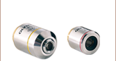
- Accepts Microscope Objectives
- High-Precision Differential Adjusters Provide Submicron Translation
- Easy-to-Follow Instructions and Alignment Tools
The KT120(/M) fiber launch system is designed to couple free-space laser beams into fiber optic cables terminated with either FC or SMA connectors. This fiber launch system is directly compatible with many of our diffraction-limited aspheres, which offer superior performance when compared to traditional microscope objectives. The C230TMD aspheric lens, which has an equivalent microscope magnification of 35X, is an ideal choice for most free-space coupling applications.
Note: The individual optomechanical parts used in the KT120 assembly are imperial or universal, while the parts used in the KT120/M assembly are metric or universal.

 Zoom
Zoom- Produces a Clean Gaussian Beam
- Wide Assortment of Compatible Pinholes, Aspheric Lenses, and Collimating Lenses
- Pre-Assembled System of Stock Catalog Components
The KT311(/M) spatial filter is ideal for producing a "clean" Gaussian beam. The input side consists of a Z-translator that will hold a diffraction-limited aspheric lens to focus the laser through a pinhole. For easy adjustment, the pinhole should be mounted in the XY translator. Threaded holes on the output side are provided for mounting and centering a Ø1" collimating optic. Please see the Tutorial tab for more information on selecting the appropriate optics and pinhole for your application.
Note: The individual optomechanical parts used in the KT311 assembly are imperial or universal while the parts used in the KT311/M assembly are metric or universal.