 Products Home / Optomechanical Components / Optomechanical Mounts / Optical Filter Mounts / Manual Filter Wheel Mounts with Neutral Density Filters
Manual Filter Wheel Mounts with Neutral Density Filters
- Convenient Lab Table Organizers for Ø1" (Ø25 mm) Optics
- Modular Design Allows for Ease of Interchangeability
- Precise Mechanical Indexing
Filters Are
Included
FW1AND
FW2AND
1.37"
(34.8 mm)
2.38"
(60.3 mm)


Please Wait
| Filter Damage Thresholds | ||
|---|---|---|
| Filters | Type | Damage Threshold |
| OD 0.2 | Pulsed | 10 J/cm2 (532 nm, 10 ns, 10 Hz, Ø0.456 mm) |
| OD 1.0 | Pulsed | 10 J/cm2 (532 nm, 10 ns, 10 Hz, Ø0.504 mm) |
| OD 2.0 | CWa,b | 12 W/cm (532 nm, Ø1.0 mm) |
| OD 4.0 | Pulsed | 5 J/cm2 (532 nm, 10 ns, 10 Hz, Ø0.340 mm) |
Features
- Single and Dual Filter Wheels
- Neutral Density (ND) Filter Sets Included
- Post-Mountable
- Compatible with Ø1" (Ø25 mm) Optics and SM1-Threaded Components
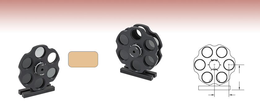
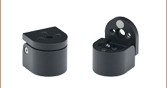
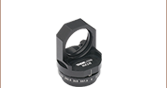
The FW1AND and FW2AND Filter Wheel Assemblies are convenient lab table organizers complete with a set of Absorptive Neutral Density (ND) filters of increasing attenuation. A precision mechanical indexer provides precise alignment and positional holding force for enhanced repeatability. The unit's base plate has two 1/4" (M6) through slots for flexible mounting on an optical table or breadboard.
The modular design allows the filter wheels to be easily interchanged and base or post mounted. For your convenience, Thorlabs offers two versions of these filter wheels, each with a filter set included, allowing the user to assemble and configure them as desired. The FW1AND is a six-position filter wheel that comes with 5 ND filters, while the FW2AND uses two six-position filter wheels and includes 10 ND filters. By combining 10 absorptive neutral density filters into a two wheel assembly (FW2AND), optical intensities can be changed over a large dynamic range (1 to 108). The ND filter values for each model are described below:
| Table 1.1 Dual Filter Wheel Optical Density and Transmission (%) Conversion Tablea |
||||||||||
|---|---|---|---|---|---|---|---|---|---|---|
| OD | 0b | 0.2 | 0.3 | 0.4 | 0.5 | 0.6 | 1.0 | 2.0 | 3.0 | 4.0 |
| 0b | 100 | 63.10 | 50.12 | 39.81 | 31.62 | 25.12 | 10.00 | 1.00 | 0.10 | 0.01 |
| 0.2 | 63.10 | - | 31.62 | 25.12 | 19.95 | 15.85 | 6.31 | 0.63 | 0.06 | 6E-3 |
| 0.3 | 50.12 | 31.62 | - | 19.95 | 15.85 | 12.59 | 5.01 | 0.50 | 0.05 | 5E-3 |
| 0.4 | 39.81 | 25.12 | 19.95 | - | 12.59 | 10.00 | 3.98 | 0.40 | 0.04 | 4E-3 |
| 0.5 | 31.62 | 19.95 | 15.85 | 12.59 | - | 7.94 | 3.16 | 0.32 | 0.03 | 3E-3 |
| 0.6 | 25.12 | 15.85 | 12.59 | 10.00 | 7.94 | - | 2.51 | 0.25 | 0.03 | 3E-3 |
| 1.0 | 10.00 | 6.31 | 5.01 | 3.98 | 3.16 | 2.51 | - | 0.10 | 0.01 | 1E-3 |
| 2.0 | 1.00 | 0.63 | 0.50 | 0.40 | 0.32 | 0.25 | 0.10 | - | 1E-3 | 1E-4 |
| 3.0 | 0.10 | 0.06 | 0.05 | 0.04 | 0.03 | 0.03 | 0.01 | 1E-3 | - | 1E-5 |
| 4.0 | 0.01 | 6E-3 | 5E-3 | 4E-3 | 3E-3 | 3E-3 | 1E-3 | 1E-4 | 1E-5 | 1E-6 |
- FW1AND Includes: 0.5, 1.0, 2.0, 3.0, and 4.0 Optical Density Absorptive ND Filters
- FW2AND Includes: 0.2, 0.3, 0.4, 0.5, 0.6, 1.0, 2.0, 3.0, and Two 4.0 Optical Density Absorptive ND Filters
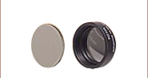
Each filter port is internally SM1 (1.035"-40) threaded and accepts Ø1" (Ø25 mm) optics up to 4.0 mm (0.16") thick when secured using the included SM1RR retaining ring (one SM1RR included for each filter wheel position). Thicker optics can be mounted into an SM1 lens tube, which then may be attached to the front of the filter wheel. These filters can be arranged and replaced quickly and easily in any order desired. They are not shipped pre-mounted onto the filter wheel.
Calculation of Optical Density
Optical density (OD) indicates the attenuation factor provided by an optical filter, i.e. how much it reduces the optical power of an incident beam. OD is related to the transmission, T, by the equation
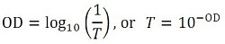
where T is a value between 0 and 1. Choosing an ND filter with a higher optical density will translate to lower transmission and greater absorption of the incident light. For higher transmission and less absorption, a lower optical density would be appropriate. As an example, if a filter with an OD of 2 results in a transmission value of 0.01, this means the filter attenuates the beam to 1% of the incident power. Please note that the transmission data for our neutral density filters is provided in percent (%).
When combining two ND filters in series, as would often be the case in the FW2AND filter wheel, the optical density values are additive. Therefore, if an OD 0.3 filter was placed in front of an OD 2.0 filter, the total OD of the optical assembly would be 2.3. This would lead to an overall transmission of 10-2.3 (~0.5%). Use Table 1.1 to determine the transmission by adding together the OD of the two filters in series.
| Table 2.1 Filter Damage Thresholds | ||
|---|---|---|
| Optical Density | Type | Damage Threshold |
| 0.2 | Pulsed | 10 J/cm2 (532 nm, 10 ns, 10 Hz, Ø0.456 mm) |
| 1.0 | Pulsed | 10 J/cm2 (532 nm, 10 ns, 10 Hz, Ø0.504 mm) |
| 2.0 | CWa,b | 12 W/cm (532 nm, Ø1.0 mm) |
| 4.0 | Pulsed | 5 J/cm2 (532 nm, 10 ns, 10 Hz, Ø0.340 mm) |
Damage Threshold Data for Thorlabs' Neutral Density Filters
The specifications in Table 2.1 are measured data for Thorlabs' neutral density filters. Damage threshold specifications are constant for a optical density, regardless of the size of the filter.
Laser Induced Damage Threshold Tutorial
The following is a general overview of how laser induced damage thresholds are measured and how the values may be utilized in determining the appropriateness of an optic for a given application. When choosing optics, it is important to understand the Laser Induced Damage Threshold (LIDT) of the optics being used. The LIDT for an optic greatly depends on the type of laser you are using. Continuous wave (CW) lasers typically cause damage from thermal effects (absorption either in the coating or in the substrate). Pulsed lasers, on the other hand, often strip electrons from the lattice structure of an optic before causing thermal damage. Note that the guideline presented here assumes room temperature operation and optics in new condition (i.e., within scratch-dig spec, surface free of contamination, etc.). Because dust or other particles on the surface of an optic can cause damage at lower thresholds, we recommend keeping surfaces clean and free of debris. For more information on cleaning optics, please see our Optics Cleaning tutorial.
Testing Method
Thorlabs' LIDT testing is done in compliance with ISO/DIS 11254 and ISO 21254 specifications.
First, a low-power/energy beam is directed to the optic under test. The optic is exposed in 10 locations to this laser beam for 30 seconds (CW) or for a number of pulses (pulse repetition frequency specified). After exposure, the optic is examined by a microscope (~100X magnification) for any visible damage. The number of locations that are damaged at a particular power/energy level is recorded. Next, the power/energy is either increased or decreased and the optic is exposed at 10 new locations. This process is repeated until damage is observed. The damage threshold is then assigned to be the highest power/energy that the optic can withstand without causing damage. A histogram such as that below represents the testing of one BB1-E02 mirror.

The photograph above is a protected aluminum-coated mirror after LIDT testing. In this particular test, it handled 0.43 J/cm2 (1064 nm, 10 ns pulse, 10 Hz, Ø1.000 mm) before damage.

| Example Test Data | |||
|---|---|---|---|
| Fluence | # of Tested Locations | Locations with Damage | Locations Without Damage |
| 1.50 J/cm2 | 10 | 0 | 10 |
| 1.75 J/cm2 | 10 | 0 | 10 |
| 2.00 J/cm2 | 10 | 0 | 10 |
| 2.25 J/cm2 | 10 | 1 | 9 |
| 3.00 J/cm2 | 10 | 1 | 9 |
| 5.00 J/cm2 | 10 | 9 | 1 |
According to the test, the damage threshold of the mirror was 2.00 J/cm2 (532 nm, 10 ns pulse, 10 Hz, Ø0.803 mm). Please keep in mind that these tests are performed on clean optics, as dirt and contamination can significantly lower the damage threshold of a component. While the test results are only representative of one coating run, Thorlabs specifies damage threshold values that account for coating variances.
Continuous Wave and Long-Pulse Lasers
When an optic is damaged by a continuous wave (CW) laser, it is usually due to the melting of the surface as a result of absorbing the laser's energy or damage to the optical coating (antireflection) [1]. Pulsed lasers with pulse lengths longer than 1 µs can be treated as CW lasers for LIDT discussions.
When pulse lengths are between 1 ns and 1 µs, laser-induced damage can occur either because of absorption or a dielectric breakdown (therefore, a user must check both CW and pulsed LIDT). Absorption is either due to an intrinsic property of the optic or due to surface irregularities; thus LIDT values are only valid for optics meeting or exceeding the surface quality specifications given by a manufacturer. While many optics can handle high power CW lasers, cemented (e.g., achromatic doublets) or highly absorptive (e.g., ND filters) optics tend to have lower CW damage thresholds. These lower thresholds are due to absorption or scattering in the cement or metal coating.

LIDT in linear power density vs. pulse length and spot size. For long pulses to CW, linear power density becomes a constant with spot size. This graph was obtained from [1].

Pulsed lasers with high pulse repetition frequencies (PRF) may behave similarly to CW beams. Unfortunately, this is highly dependent on factors such as absorption and thermal diffusivity, so there is no reliable method for determining when a high PRF laser will damage an optic due to thermal effects. For beams with a high PRF both the average and peak powers must be compared to the equivalent CW power. Additionally, for highly transparent materials, there is little to no drop in the LIDT with increasing PRF.
In order to use the specified CW damage threshold of an optic, it is necessary to know the following:
- Wavelength of your laser
- Beam diameter of your beam (1/e2)
- Approximate intensity profile of your beam (e.g., Gaussian)
- Linear power density of your beam (total power divided by 1/e2 beam diameter)
Thorlabs expresses LIDT for CW lasers as a linear power density measured in W/cm. In this regime, the LIDT given as a linear power density can be applied to any beam diameter; one does not need to compute an adjusted LIDT to adjust for changes in spot size, as demonstrated by the graph to the right. Average linear power density can be calculated using the equation below.

The calculation above assumes a uniform beam intensity profile. You must now consider hotspots in the beam or other non-uniform intensity profiles and roughly calculate a maximum power density. For reference, a Gaussian beam typically has a maximum power density that is twice that of the uniform beam (see lower right).
Now compare the maximum power density to that which is specified as the LIDT for the optic. If the optic was tested at a wavelength other than your operating wavelength, the damage threshold must be scaled appropriately. A good rule of thumb is that the damage threshold has a linear relationship with wavelength such that as you move to shorter wavelengths, the damage threshold decreases (i.e., a LIDT of 10 W/cm at 1310 nm scales to 5 W/cm at 655 nm):

While this rule of thumb provides a general trend, it is not a quantitative analysis of LIDT vs wavelength. In CW applications, for instance, damage scales more strongly with absorption in the coating and substrate, which does not necessarily scale well with wavelength. While the above procedure provides a good rule of thumb for LIDT values, please contact Tech Support if your wavelength is different from the specified LIDT wavelength. If your power density is less than the adjusted LIDT of the optic, then the optic should work for your application.
Please note that we have a buffer built in between the specified damage thresholds online and the tests which we have done, which accommodates variation between batches. Upon request, we can provide individual test information and a testing certificate. The damage analysis will be carried out on a similar optic (customer's optic will not be damaged). Testing may result in additional costs or lead times. Contact Tech Support for more information.
Pulsed Lasers
As previously stated, pulsed lasers typically induce a different type of damage to the optic than CW lasers. Pulsed lasers often do not heat the optic enough to damage it; instead, pulsed lasers produce strong electric fields capable of inducing dielectric breakdown in the material. Unfortunately, it can be very difficult to compare the LIDT specification of an optic to your laser. There are multiple regimes in which a pulsed laser can damage an optic and this is based on the laser's pulse length. The highlighted columns in the table below outline the relevant pulse lengths for our specified LIDT values.
Pulses shorter than 10-9 s cannot be compared to our specified LIDT values with much reliability. In this ultra-short-pulse regime various mechanics, such as multiphoton-avalanche ionization, take over as the predominate damage mechanism [2]. In contrast, pulses between 10-7 s and 10-4 s may cause damage to an optic either because of dielectric breakdown or thermal effects. This means that both CW and pulsed damage thresholds must be compared to the laser beam to determine whether the optic is suitable for your application.
| Pulse Duration | t < 10-9 s | 10-9 < t < 10-7 s | 10-7 < t < 10-4 s | t > 10-4 s |
|---|---|---|---|---|
| Damage Mechanism | Avalanche Ionization | Dielectric Breakdown | Dielectric Breakdown or Thermal | Thermal |
| Relevant Damage Specification | No Comparison (See Above) | Pulsed | Pulsed and CW | CW |
When comparing an LIDT specified for a pulsed laser to your laser, it is essential to know the following:

LIDT in energy density vs. pulse length and spot size. For short pulses, energy density becomes a constant with spot size. This graph was obtained from [1].
- Wavelength of your laser
- Energy density of your beam (total energy divided by 1/e2 area)
- Pulse length of your laser
- Pulse repetition frequency (prf) of your laser
- Beam diameter of your laser (1/e2 )
- Approximate intensity profile of your beam (e.g., Gaussian)
The energy density of your beam should be calculated in terms of J/cm2. The graph to the right shows why expressing the LIDT as an energy density provides the best metric for short pulse sources. In this regime, the LIDT given as an energy density can be applied to any beam diameter; one does not need to compute an adjusted LIDT to adjust for changes in spot size. This calculation assumes a uniform beam intensity profile. You must now adjust this energy density to account for hotspots or other nonuniform intensity profiles and roughly calculate a maximum energy density. For reference a Gaussian beam typically has a maximum energy density that is twice that of the 1/e2 beam.
Now compare the maximum energy density to that which is specified as the LIDT for the optic. If the optic was tested at a wavelength other than your operating wavelength, the damage threshold must be scaled appropriately [3]. A good rule of thumb is that the damage threshold has an inverse square root relationship with wavelength such that as you move to shorter wavelengths, the damage threshold decreases (i.e., a LIDT of 1 J/cm2 at 1064 nm scales to 0.7 J/cm2 at 532 nm):

You now have a wavelength-adjusted energy density, which you will use in the following step.
Beam diameter is also important to know when comparing damage thresholds. While the LIDT, when expressed in units of J/cm², scales independently of spot size; large beam sizes are more likely to illuminate a larger number of defects which can lead to greater variances in the LIDT [4]. For data presented here, a <1 mm beam size was used to measure the LIDT. For beams sizes greater than 5 mm, the LIDT (J/cm2) will not scale independently of beam diameter due to the larger size beam exposing more defects.
The pulse length must now be compensated for. The longer the pulse duration, the more energy the optic can handle. For pulse widths between 1 - 100 ns, an approximation is as follows:

Use this formula to calculate the Adjusted LIDT for an optic based on your pulse length. If your maximum energy density is less than this adjusted LIDT maximum energy density, then the optic should be suitable for your application. Keep in mind that this calculation is only used for pulses between 10-9 s and 10-7 s. For pulses between 10-7 s and 10-4 s, the CW LIDT must also be checked before deeming the optic appropriate for your application.
Please note that we have a buffer built in between the specified damage thresholds online and the tests which we have done, which accommodates variation between batches. Upon request, we can provide individual test information and a testing certificate. Contact Tech Support for more information.
[1] R. M. Wood, Optics and Laser Tech. 29, 517 (1998).
[2] Roger M. Wood, Laser-Induced Damage of Optical Materials (Institute of Physics Publishing, Philadelphia, PA, 2003).
[3] C. W. Carr et al., Phys. Rev. Lett. 91, 127402 (2003).
[4] N. Bloembergen, Appl. Opt. 12, 661 (1973).
| Posted Comments: | |
Bandi Parapak
(posted 2025-03-12 12:41:04.71) We are interested in ordering items :
FW1AND - Six Station Single Filter Wheel for Ø1" (Ø25 mm) Filters with Base Assembly, 5 ND Filters Included. Therefore please send the quotation to us as soon as possible. cdolbashian
(posted 2025-03-20 12:03:51.0) Thank you for reaching out to us with this quotation request. I have put you in contact with your local sales team to assist with such a purchase. Shree Krishnamoorthy
(posted 2021-11-10 13:38:51.887) Dear Thorlabs team, I was looking for characterization of the filters in NIR region (1100-2500 nm). could you comment on the OD for FW1AND filterwheel filters for these? YLohia
(posted 2021-11-12 04:16:06.0) Hello Shree, the extended range OD for the FW1AND can be downloaded by clicking on the hyperlinked nominal OD values on the Overview tab for this wheel and then selecting the download link for the raw data transmission/OD values as an Excel file. Dimitri Kromm
(posted 2020-07-09 11:21:31.56) Dear Thorlabs-Team,
I'm generally a big fan of the fact that you have SolidWorks models of most of your components. However, I would recommend to update the model of the FW1AND as the point of origin, the planes and the position of the "ND-wheel" are not useful, or at least I don't see how they would be.
I would suggest to rotate the wheel as shown in the pdf such that the height from bottom to the used window becomes 55mm, then either put the origin into that window or at least have a logical position in regards to the beam/whole position. That would make the usage and incorporation into other setups easier. Please consider my feedback on this. Thanks!
Kind regards,
Dimitri llamb
(posted 2020-07-15 04:22:24.0) Hello Dimitri, thank you for your feedback. We will certainly consider updating the FW1AND's SolidWorks file's point of origin to be more versatile in other assemblies. hmendez
(posted 2018-03-06 11:22:58.383) I please need detailed info to ensure my laser will not damage the ND filters: ND 0.2 1.0 and 3.0
in order to calculate an 1w CW laser 1,5mm diameter could work fine, without burning the ND filter. (I mean 500w/cm2 for the ND1.0 is too much power).
thanks in advance.
hm llamb
(posted 2018-03-12 05:07:13.0) Hello, thank you for contacting Thorlabs. The damage threshold will also depend on the wavelength of your light. While we do not have formal testing for damage threshold, I will reach out to you directly to help estimate. werner.engel
(posted 2016-05-12 18:57:16.537) It would be nice to get a suggestion for filling the FW2AND with the filters in the right position.
I have them in front of me and now I have to start calculating ... :-( besembeson
(posted 2016-05-12 03:18:01.0) Response from Bweh at Thorlabs USA: Each of the wheels can be rotated independently so it is not very relevant where they are positioned except for the two with OD of 4, that must be on each wheel to get the maximum attenuation of 10^-8. You may for example consider having 0.2, 0.3, 0.4, 0.5, 4 on the first wheel and then 0.6, 1.0, 2.0, 3.0, 4.0 on the second wheel. We will add suggestive notes on the website regarding this. tcohen
(posted 2012-12-05 10:42:00.0) Response from Tim at Thorlabs to Arunasish: The performance of these filters can be viewed by clicking on the hyperlinks in the Overview tab. These absorptive ND filters have extremely high OD in UV and will not be suitable with a 230nm source. We have reflective UVFS substrates which can be used with your source at http://www.thorlabs.com/newgrouppage9.cfm?objectgroup_id=6106. As the OD typically increases towards your wavelength, consulting the typical OD spectrum, all of which are available on the ‘Graphs’ tab, would be necessary. arunasis
(posted 2012-11-30 16:20:21.533) Hi,
I have like to know some specific information about the ND filter (FW2AND). Does this filter wheel work in the UV region (upto 230 nm) and what is the maximum power that is suitable for the this wheel. (I mean beyond which power the coatings are vulnerable to be damaged?)
Looking forward to hearing back from you.
Thanks,
Arunasish Greg
(posted 2011-01-24 11:20:07.0) A response from Greg at Thorlabs: Thank you for your feedback! I have added transmission data for each of the filters as well as links to support documents for these filters on the Overview tab. To find the information, just click on the neutral density you are interested in and a window will pop up. user
(posted 2011-01-24 10:42:32.0) It would be useful to reference the part numbers for the filters on this page for easy cross-reference to the transmission data. |