Products Home
USB Motion Control 19" Rack Chassis
- Up to 12 Drive Channels in a Single Chassis
- DC Servo Motor, Stepper Motor, Piezo, and Auto-Alignment Driver Module
- Ideal for Creating Multi-Axis Integrated Positioning Systems
MMR601
Full Suite of Software Support Tools Included


Please Wait
| Rack System Motion Controller Modules |
|---|
| 2-Channel Brushless DC Motor Controller Module |
| 2-Channel Stepper Motor Controller Module |
| 2-Channel Piezo Controller Module |
| 2-Channel NanoTrak® Auto-Alignment Module |
| USB Motion Control 19" Rack Chassis |
Features
- Four Dual-Channel Plug-in Modules
- Brushless DC Motor Controller
- Stepper Motor Controller
- Piezoelectric Controller
- NanoTrak® Auto-Alignment Controller
- Room for 6 Modules per 4U Chassis
- USB Plug-and-Play
- Multiple Racks Controlled by a Single Host PC
- Full Kinesis Software Control Suite Included
- Intuitive Software Graphical Control Panels
- Fully Software Integrated with Other Thorlabs Motion Controllers (Integrated Systems Development)
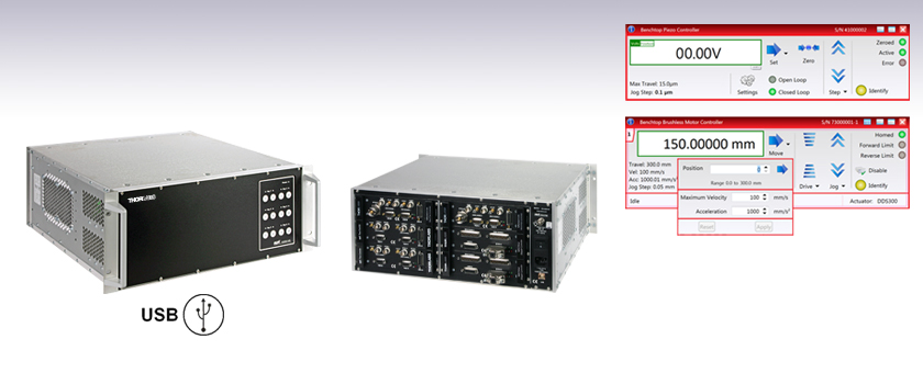
The MMR601(602) 19" Rack System is a multi-channel, multi-function modular architecture designed specifically for high axis count motion control applications. This system is a sophisticated, self-contained, extendable-architecture, precision motion control platform. As a modular system it is possible to load it with the exact number and mix of required controller modules covering brushless motor drives (MBD), stepper motor drives (MST), piezo drives (MPZ), and the powerful Thorlabs NanoTrak® autoalignment technology (MNA). It deploys the same advanced high-speed digital signal processing (DSP) technology and low-noise analog circuitry pioneered in our equivalent benchtop controllers.
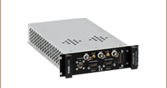
The modular rack is available with a cover (Item # MMR602) for benchtop use, or without a cover (Item #MMR601) for mounting in a standard 19" cabinet, and provides a highly functional 12 channel platform within the footprint of a 4U, 19" rack enclosure.
USB connectivity provides easy 'Plug-and-Play' PC-controlled operation with our Kinesis software package. The Kinesis Software features .NET controls, which can be used by third-party developers working in the latest C, C#, Visual Basic, LabVIEW™, or any .NET-compatible languages to create custom applications. For more details on the software package, please see the Kinesis Software and Kinesis Tutorials tabs.
It is perfectly feasible to combine operation of this rack system with any of the benchtop controllers and control everything from the same unified Kinesis software interface, allowing a common learning curve for both benchtop and rack based solutions.
Cabling
Cables for connecting actuators or stages to the controller are shipped with the actuators or stages, not the controller. If you need help identifying the appropriate replacement cable, please contact Tech Support.
Motion Control 19" Rack Chassis
| Item # | MMR601 & MMR602 |
|---|---|
| Enclosure | Standard 19" Rack, 4U High |
| Module Bays | 6 Modular Slots, Back Panel Access |
| Communications | USB 1.1 Interface |
| Power Input | |
| Voltage | 85 - 264 V AC |
| Frequency | 47 - 63 Hz |
| Power | 800 W |
| Fuse | 15 A |
| Dimensions (W x D x H) | 480 mm x 448 mm x 183 mm (19.0" x 17.6" x 7.0") |
| Weight | 16 kg (35.2 lbs) |
Brushless DC Motor Controller
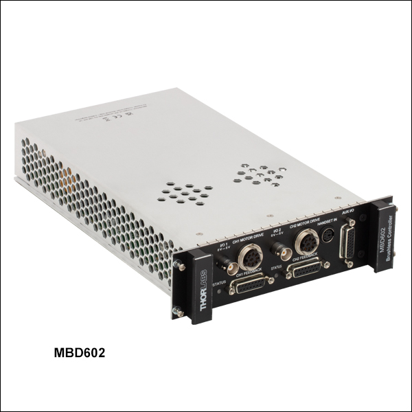
| Item # | MBD602 |
|---|---|
| Number of Channels | 2 |
| Motor Drive Connector | 8-Pin DIN-Type, Female (Motor Phase Outputs, Stage ID Input) |
| Feedback Connector | 15-Pin D-Type, Female |
| Brushless Continuous Current Output | 2.5 A per Channel (5.0 A Max All-Channel Output) |
| Brushless Peak Current Output | 4.0 A per Channel (5.2 A Max All-Channel Output) |
| Pulse-Width Modulation Frequency | 20 kHz |
| Operating Modes | Position and Velocity |
| Control Algorithm | 16-Bit Digital PID Servo Loop with Velocity and Acceleration Feed Forward |
| Velocity Profile | Trapezoidal |
| Position Count | 32-Bit |
| Position Feedback | Incremental Encoder |
| Encoder Bandwidth | 2.5 MHz (10 M Counts/sec) |
| Encoder Supply | 5 V |
| AUX Control Connector | 26-Way High Density D-Type, Female (User Digital IO, 5 V O/P) |
| Input Power Requirements | Power: 250 VA Voltage: 100 to 240 V AC Frequency: 47 to 63 Hz |
| Dimensions | 187 mm x 286.6 mm x 50.4 mm (7.36" x 11.28" x 1.98") |
| Weight | 0.9 kg (1.98 lbs) |
| Compatible Motor Specs | 3-Phase DC Brushless Motors with Peak Power: 100 W, Coil Resistance: 0.1 to 100 Ω, Coil Inductance (Nominal): 1 to 100 mH, and Rated Phase Current (Nominal): 100 mA to 5 A |
Stepper Motor Controller
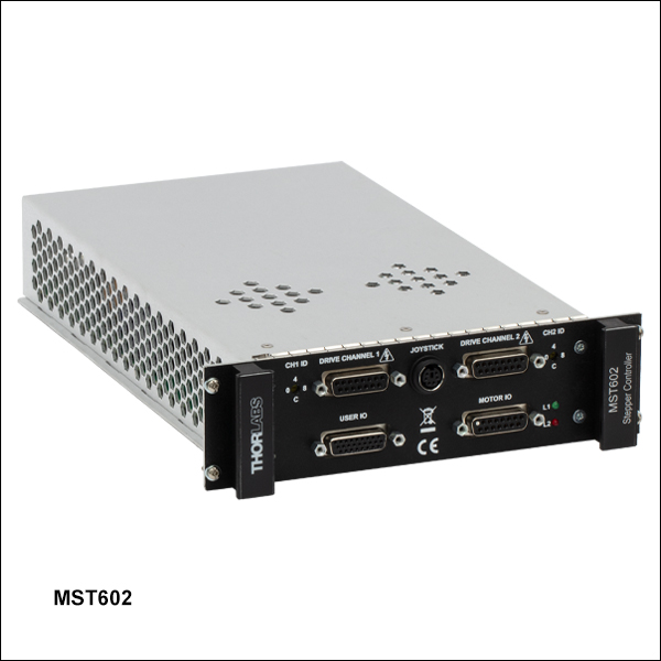
| Item # | MST602 |
|---|---|
| Number of Channels | 2 |
| Motor Drive Connector | 15-Pin D-Type, Female 2-Phase Bi-Polar Motor Drive Output Differential Quadrature Encoder (QEP) Input Forward, Reverse Limit Switch Inputs Encoder 5 V (with Ground) |
| Motor Control Connector | 15-Pin D-Type, Female Jog Forward/Back Input (TTL) Enable/Disable Interlock (per Channel) Connect to Return to Operate Motor User 5 V (with Ground) 100 mA Max |
| User I/O Connector | 26-Pin D-Type, Female 4 Logic Inputs (TTL) 4 Logic Outputs (Open Collector) Trigger Input (TTL) Trigger Output (Open Collector) 2 Analog Inputs, Single Ended 0 - 10 V (12-Bit) |
| Resolution | 2048 Microsteps per Full Step 200 Step Motor - 409 600 Microsteps per Rev 24 Step Motor - 49 152 Microsteps/Rev |
| Motor Drive Voltage | Up to 48 V |
| Motor Drive Power | Up to 50 Wpeak/25 Wavg |
| Motor Speeds | Up to 3000 RPM (for 200 Full Step Motor) |
| Encoder Feedback Bandwidth | 500 kHz |
| Compatible Motor Specs | 2-Phase Bi-Polar Stepper Motors with Peak Powers: 5 to 50 W, Average Power: 25 W Maximum Step Angle Range: 20° to 1.8° Coil Resistance (Nominal): 4 to 15 Ω, Coil Inductance (Nominal): 4 to 15 mH Rated Phase Current (Nominal): 100 mA to 1 A |
| Housing | Single Rack System Bay |
| Dimensions (W x D x H) | 190 mm x 270 mm x 50 mm (7.5" x 10.6" x 2.0") |
| Weight | 1.5 kg (3.3 lbs) |
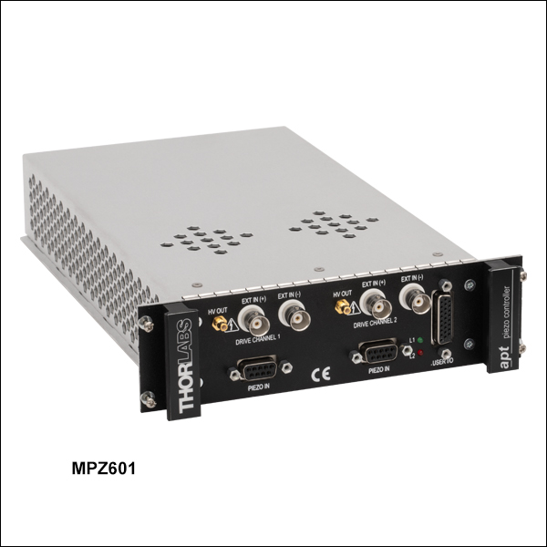
Piezo Controller
| Item # | MPZ601 |
|---|---|
| Number of Channels | 2 |
| Piezoelectric Output (SMC Male) - Per Channel | |
| Voltage (Software Control) | 0 to 75 V DC |
| Voltage (External Input) | -10 to 90 V DC |
| Current | 500 mA Max Continuous |
| Stability | 100 ppm Over 24 hours (After 30 mins Warm-Up Time) |
| Noise | <3 mV RMS |
| Typical Piezo Capacitance | 1 to 10 µF |
| Bandwidth | 10 kHz (1 µF Load, 1 Vp-p) |
| Position Feedback (9-Pin D-Type Female) - Per Channel | |
| Feedback Type | AC Bridge or 0-10 V Differential DC (SW Selectable) |
| AC Feedback Transducer Type | Strain Gauge |
| AC Detection Method | AC Bridge (18 kHz Excitation) |
| Typical AC Feedback Resolution | 5 nm (for 20 µm Actuator e.g. PAZ005) |
| Auto-Configure | Identification Resistance in Actuator |
| User Input/Output (26-Pin D-Type Female) | |
| Potentiometer Input (Per Channel) | Reference + Wiper (50 kΩ 10 Turn Pots) |
| HV Output Monitor (Per Channel) | 0 to 10 V DC |
| 4 Digital Inputs | TTL Levels |
| 4 Digital Outputs | Open Collector |
| Trigger Input/Output | TTL |
| Trigger Input Functionality | Triggered Voltage Ramps/Waveforms |
| Trigger Output Functionality | Trigger Generation During Voltage Ramp Output |
| User 5 V (with Ground) 250 mA Max | |
| General | |
| Housing | Single Rack System Bay |
| Dimensions (W x D x H) | 190 mm x 270 mm x 50 mm (7.5" x 10.6" x 2.0") |
| Weight | 1.5 kg (3.3 lbs) |
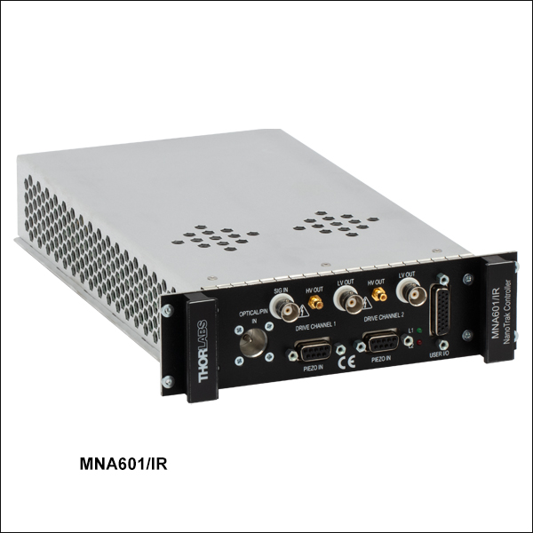
NanoTrak® Active Auto-Alignment Module
| Item # | MNA601/IR | |
|---|---|---|
| Number of Channels | 2 | |
| Signal Measurement | ||
| PIN Photodiode | ||
| Mechanical Connector | SMB Male | |
| Photocurrent Range | 1 nA to 10 mA | |
| Optical Connector | FC/PC | |
| NanoTraking | ||
| Circle Scanning Frequency | 1 to 300 Hz | |
| Circle Position Range | <1% to >99% MPE | |
| Circle Diameter Adj. Modes | Automatic and Manual | |
| Signal Phase Compensation | ±180° | |
| Piezoelectric Input/Output | ||
| Number of Piezo Channels | 2 | |
| HV Output Connectors | ||
| Connector Type | SMC Male | |
| Voltage Output | 0 to 75 VDC/Channel | |
| Voltage Stability | 100 ppm over 24 Hours | |
| Noise | <3 mV (RMS) | |
| Output Current | 500 mA/Channel | |
| Analog Output Monitors | ||
| Connector Type | BNC | |
| Voltage Range | 0 to 10 VDC | |
| Strain Gauge Position Feedback | ||
| Connector Type | 9-Pin D-Type Female | |
| Feedback Type | AC | |
| Other Input/Output | ||
| Optical Power Monitor | ||
| Connector Type | BNC | |
| Voltage Range | 0 to 10 VDC | |
| Ext Signal In Input | ||
| Connector Type | BNC | |
| Voltage Range | 0 to 10 VDC | |
| User Control | ||
| Connector Type | 26-Pin HD D-Type Female | |
| Isolated Digital Inputs | 4 off TTL | |
| Isolated Digital Outputs | 4 off TTL | |
| Trigger Input | 1 off TTL | |
| Trigger Output | 1 off TTL | |
| Potentiometer Channel Ctrl Input | 1 - 10 kΩ (Each Channel) | |
| Analog Channel Output Monitors | 0 to 10 VDC (Each Channel) | |
| General | ||
| Dimensions (W x D x H) | 190 mm x 270 mm x 50 mm (7.5" x 10.6" x 2.0") | |
| Weight | 1.5 kg (3.3 lbs) | |
| Optical Detector Specifications for MNA601/IR | ||
|---|---|---|
| Item # | NTA009 (Sold Separately) | NTA007 (Included with Controller) |
| Detector Type | Si | InGaAs |
| Operating Wavelength | 320 - 1000 nm | 900 - 1700 nm |
| Active Area | Ø0.8 mm | Ø0.12 mm |
| Fiber Input | FC/PC | |
| Rise Time | 100 ps @ 12 V | |
| NEP | 1.5 x 10⁻¹⁵ W/√Hz | 4.5 x 10⁻¹⁵ W/√Hz |
| Dark Current | 0.01 nA (Typ.) @ 10 V | 0.05 nA (Typ.) @ 5 V |
| Junction Capacitance | 3.00 pF (Typ.) @ 10 V | 2.0 pF (Typ.) @ 5 V |
Control Module Pin Diagrams
MBD602 Brushless DC Motor Controller Module
MOTOR DRIVE
8-Pin DIN-Type, Female
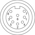
| Pin | Description | Pin | Description |
|---|---|---|---|
| 1 | Motor Phase B | 5 | Stage ID |
| 2 | GND | 6 | Enable |
| 3a | Motor Phase D | 7 | Motor Phase C |
| 4 | Motor Phase A | 8a | +5 V |
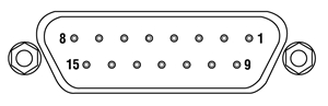
FEEDBACK
15-Pin D-Type, Female
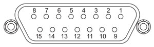
| Pin | Description | Pin | Description |
|---|---|---|---|
| 1 | Not Connected | 9 | GND |
| 2 | GND | 10 | Limit Switch + |
| 3 | Not Connected | 11 | Limit Switch - |
| 4 | Index - | 12 | Index + |
| 5 | QB - | 13 | QB + |
| 6 | QA - | 14 | QA + |
| 7a | 5 V | 15 | Not Connected |
| 8a | 5 V |
HANDSET
Mini DIN Female
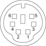
| Pin | Description | Pin | Description |
|---|---|---|---|
| 1 | RX (Controller Input) | 4b | Supply Voltage for Handset 5 V |
| 2a | Ground | 5 | TX (Controller Output) |
| 3a | Ground | 6a | Ground |
AUX I/O
26-Way High Density D-Type, Female
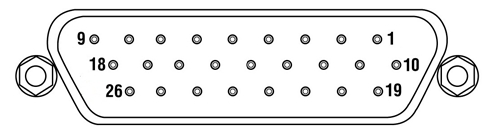
| Pin | Description | Function | Pin | Description | Function | Pin | Description | Function |
|---|---|---|---|---|---|---|---|---|
| 1a | Digital I/P 3 |
- | 10a | Digital O/P 3 |
- | 19c | Ground | - |
| 2a | Digital I/P 2 |
- | 11a | Digital O/P 2 |
- | 20e | Digital O/P 2+ |
Motor #1 Encoder B+ |
| 3a | Digital I/P 1 |
- | 12a | Digital O/P 1 |
- | 21e | Digital O/P 2- |
Motor #1 Encoder B- |
| 4a | Digital I/P 0 |
- | 13a | Digital O/P 0 |
- | 22e | Ground | - |
| 5e | Digital O/P 6- |
Motor #2 Encoder A- | 14e | Digital O/P 4+ |
Motor #2 Encoder IX+ | 23d | 5 V | - |
| 6e | Digital O/P 6+ |
Motor #2 Encoder A+ | 15e | Digital O/P 4- |
Motor #2 Encoder IX- | 24e | Digital O/P 1+ |
Motor #1 Encoder IX+ |
| 7e | Digital O/P 5+ |
Motor #2 Encoder B+ | 16e | Digital O/P 3- |
Motor #1 Encoder A- | 25e | Digital O/P 1- |
Motor #1 Encoder IX- |
| 8e | Digital O/P 5- |
Motor #2 Encoder B- | 17e | Digital O/P 3+ |
Motor #1 Encoder A+ | 26c | Ground | - |
| 9b | RS-232 RX | - | 18b | RS-232 TX | - |
MST602 Stepper Motor Controller Module
Motor I/O Controller
D-Type Female
| Pin | Description | Return | Pin | Description | Return | Pin | Description | Return |
|---|---|---|---|---|---|---|---|---|
| 1 | User 5 V I/O | 9 | 6 | Channel 2 Emergency Stop Daisy Chain Link Returnb | 14 | 11 | Channel 2 Jog Backwardsa | 9 |
| 2 | Channel 1 Jog Forwardsa | 9 | 7 | Channel 2 Enable Returnb | 15 | 12 | Channel 1 Emergency Stop Daisy Chain Linkb | 4 |
| 3 | Channel 2 Jog Forwardsa | 9 | 8 | Not Used | - | 13 | Channel 1 Enableb | 5 |
| 4 | Channel 1 Emergency Stop Daisy Chain Link Returnb | 12 | 9 | User 0 V | - | 14 | Channel 2 Emergency Stop Daisy Chain Linkb | 6 |
| 5 | Channel 1 Enable Returnb | 13 | 10 | Channel 1 Jog Backwardsa | 9 | 15 | Channel 2 Enableb | 7 |
User I/O Controller
D-Type Female
| Pin | Description | Return | Pin | Description | Return | Pin | Description | Return |
|---|---|---|---|---|---|---|---|---|
| 1 | Digital I/P 1 | 19 | 10 | Digital O/P 1 | 19 | 19 | Digital Ground 1 (0 V)c | - |
| 2 | Digital I/P 2 | 19 | 11 | Digital O/P 2 | 19 | 20 | Ext Trigger I/P | 22 |
| 3 | Digital I/P 3 | 19 | 12 | Digital O/P 3 | 19 | 21 | Ext Trigger O/P | 22 |
| 4 | Digital I/P 4 | 19 | 13 | Digital O/P 4 | 19 | 22 | Digital Ground 2 (0 V)c | - |
| 5 | Channel 1 RS232 TX | - | 14 | Channel 2 RS232 TX | - | 23 | 5 V User O/P (50 mA Max.) | - |
| 6 | Channel 1 RS232 RX | - | 15 | Channel 2 RS232 RX | - | 24 | Reserved for Future Use | - |
| 7 | Not Used | - | 16 | Reserved for Future Use | - | 25 | Reserved for Future Use | - |
| 8 | Channel 2 Analog I/P (+)b | 17 | 17 | 0 V (Analog Rtn)b | 8 | 26 | Analoga Ground (0 V)c |
- |
| 9 | Channel 1 Analog I/P (+)b | 18 | 18 | 0 V (Analog Rtn)b | 9 |
Drive Channel Connector
D-Type Female
| Pin | Description | Pin | Description | Pin | Description |
|---|---|---|---|---|---|
| 1 | Encoder A +ve | 6 | Not Used | 11 | 0 V User |
| 2 | Encoder A -ve | 7 | Phase B - | 12 | Reserved for Future Use |
| 3 | Encoder B +ve | 8 | Phase A - | 13 | Reserved for Future Use |
| 4 | Encoder B -ve | 9 | CW Limit Switch | 14 | Phase B + |
| 5 | 5 V User | 10 | CCW Limit Switch | 15 | Phase A + |
Handset
Mini DIN Female
| Pin | Description | Pin | Description |
|---|---|---|---|
| 1 | RX (Controller Input)/RS232 | 4 | Supply Voltage for Handset 5 V |
| 2 | Ground | 5 | TX (Controller Output) |
| 3 | Ground | 6 | Ground |
MPZ601 Piezo Controller Module
User I/O Controller
D-Type Female
| Pin | Description | Return | Pin | Description | Return | Pin | Description | Return |
|---|---|---|---|---|---|---|---|---|
| 1 | DIG I/P 1a | 19 | 10 | DIG O/P 1a | 19 | 19 | Isolated Groundb | - |
| 2 | DIG I/P 2a | 19 | 11 | DIG O/P 2a | 19 | 20 | Ext Trigger I/P | 22 |
| 3 | DIG I/P 3a | 19 | 12 | DIG O/P 3a | 19 | 21 | Ext Trigger O/P | 22 |
| 4 | DIG I/P 4a | 19 | 13 | DIG O/P 4a | 19 | 22 | Ground | - |
| 5 | Channel 1 RS485 (+) | - | 14 | Channel 2 RS485 (+) | - | 23 | 5 V User O/P (Isolated) | - |
| 6 | Channel 1 RS485 (-) | - | 15 | Channel 2 RS485 (+) | - | 24 | Not Used | - |
| 7 | Not Used | - | 16 | Not Used | - | 25 | Analog or Potentiometer Ground | - |
| 8 | Channel 2 10 V O/Pc | 25 | 17 | Potentiometer Wiper Ch 2 | - | 26 | Potentiometer Reference | 25 |
| 9 | Channel 1 10 V O/Pc | 25 | 18 | Potentiometer Wiper Ch 2 | - |
Piezo Controller
D-Type Female
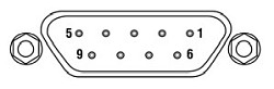
| Pin | Description | Return | Pin | Description | Return | Pin | Description | Return |
|---|---|---|---|---|---|---|---|---|
| 1 | Wheatstone Bridge Excitation | 4 or 6 | 4 | DC(+) or Equipment Groundc | - | 7 | DC(-) or Actuator ID Signalb,c | 4 or 6 |
| 2 | +15 Va | 4 or 6 | 5 | Feedback Signal In | 4 or 6 | 8 | RS485 (-) | 9 |
| 3 | -15 Va | 4 or 6 | 6 | Equiptment Ground | - | 9 | RS485 (+) | 8 |
Ext In (+) and Ext In (-)
BNC Female
Differential Inputs. The output from the HV amplifier circuit can be set to be controlled, in part, by the differential signal on these two inputs. If the Input Source is set to include a BNC option, the unit sums this differential signal with any other input sources selected (voltage set using the GUI panel 'Output' control and voltage from an external potentiometer).
HV Out
SMC

0 to 75 V, 0 to 250 mA. Provides the drive signal to the piezo actuator.
MNA601/IR NanoTrak® Active Auto-Alignment Module
User I/O Controller
D-Type Female
| Pin | Description | Return | Pin | Description | Return | Pin | Description | Return |
|---|---|---|---|---|---|---|---|---|
| 1 | DIG I/P 1a | 19 | 10 | DIG O/P 1a | 19 | 19 | Isolated Groundb | - |
| 2 | DIG I/P 2a | 19 | 11 | DIG O/P 2a | 19 | 20 | Ext Trigger I/P | 22 |
| 3 | DIG I/P 3a | 19 | 12 | DIG O/P 3a | 19 | 21 | Ext Trigger O/P | 22 |
| 4 | DIG I/P 4a | 19 | 13 | DIG O/P 4a | 19 | 22 | Ground | - |
| 5 | Channel 1 RS485 (+) | - | 14 | Channel 2 RS485 (+) | - | 23 | 5 V User O/P (Isolated) | - |
| 6 | Channel 1 RS485 (-) | - | 15 | Channel 2 RS485 (+) | - | 24 | Not Used | - |
| 7 | Not Used | - | 16 | Not Used | - | 25 | Analog Ground | - |
| 8 | Channel 2 10 V O/Pc | 25 | 17 | External Analog I/P CH2 0 - 10 V | 25 | 26 | Signal Power Outd | 25 |
| 9 | Channel 1 10 V O/Pc | 25 | 18 | External Analog I/P CH1 0 - 10 V | 25 |
Piezo Controller
D-Type Female
| Pin | Description | Return | Pin | Description | Return | Pin | Description | Return |
|---|---|---|---|---|---|---|---|---|
| 1 | Wheatstone Bridge Excitation | 4 or 6 | 4 | DC(+) or Equipment Grounda | - | 7 | DC(-) or Actuator ID Signala,b | 4 or 6 |
| 2 | +15 Vc | 4 or 6 | 5 | Feedback Signal In | 4 or 6 | 8 | RS485 (-) | 9 |
| 3 | -15 Vc | 4 or 6 | 6 | Equiptment Ground | - | 9 | RS485 (+) | 8 |
LV Out
BNC Female
0 to +10 V. This output is mirrors HV OUT, 10 V being equivalent to 75 V on the HV outputs, and can be connected to an oscilloscope to enable the drive signal of the piezo actuator to be monitored.
HV Out
SMC
0 to 75 V, 0 to 500 mA. Provides the drive signal to the piezo actuator.
Signal In
BNC Female
0 to 10 V, 100 kΩ load. Used to receive a signal of optical power from an external power meter.
Piezo Driver Bandwidth Tutorial
Knowing the rate at which a piezo is capable of changing lengths is essential in many high-speed applications. The bandwidth of a piezo controller and stack can be estimated if the following is known:
- The maximum amount of current the controllers can produce. This is 0.5 A for our BPC Series Piezo Controllers, which is the driver used in the examples below.
- The load capacitance of the piezo. The higher the capacitance, the slower the system.
- The desired signal amplitude (V), which determines the length that the piezo extends.
- The absolute maximum bandwidth of the driver, which is independent of the load being driven.
To drive the output capacitor, current is needed to charge it and to discharge it. The change in charge, dV/dt, is called the slew rate. The larger the capacitance, the more current needed:
For example, if a 100 µm stack with a capacitance of 20 µF is being driven by a BPC Series piezo controller with a maximum current of 0.5 A, the slew rate is given by
Hence, for an instantaneous voltage change from 0 V to 75 V, it would take 3 ms for the output voltage to reach 75 V.
Note: For these calculations, it is assumed that the absolute maximum bandwidth of the driver is much higher than the bandwidths calculated, and thus, driver bandwidth is not a limiting factor. Also please note that these calculations only apply for open-loop systems. In closed-loop mode, the slow response of the feedback loop puts another limit on the bandwidth.
Sinusoidal Signal
The bandwidth of the system usually refers to the system's response to a sinusoidal signal of a given amplitude. For a piezo element driven by a sinusoidal signal of peak amplitude A, peak-to-peak voltage Vpp, and frequency f, we have:
A diagram of voltage as a function of time is shown to the right. The maximum slew rate, or voltage change, is reached at t = 2nπ, (n=0, 1, 2,...) at point a in the diagram to the right:
From the first equation, above:

Thus,
For the example above, the maximum full-range (75 V) bandwidth would be
 .
.
For a smaller piezo stack with 10 times lower capacitance, the results would be 10 times better, or about 1060 Hz. Or, if the peak-to-peak signal is reduced to 7.5 V (10% max amplitude) with the 100 µm stack, again, the result would be 10 times better at about 1060 Hz.
Triangle Wave Signal
For a piezo actuator driven by a triangle wave of max voltage Vpeak and minimum voltage of 0, the slew rate is equal to the slope:
![]() .
.
Or, since f = 1/T:
Square Wave Signal
For a piezo actuator driven by a square wave of maximum voltage Vpeak and minimum voltage 0, the slew rate limits the minimum rise and fall times. In this case, the slew rate is equal to the slope while the signal is rising or falling. If tr is the minimum rise time, then
or
 .
.
For additional information about piezo theory and operation, see the Piezoelectric Tutorials page.
Software
Kinesis Version 1.14.53
The Kinesis Software Package, which includes a GUI for control of Thorlabs' Kinesis system controllers.
Also Available:
- Communications Protocol

Figure 58A Kinesis GUI Screen
Thorlabs offers the Kinesis software package to drive our wide range of motion controllers. The software can be used to control devices in the Kinesis family, which covers a wide variety of motion controllers ranging from small, low-powered, single-channel drivers (such as the K-Cubes®) to high-power, multi-channel benchtop units and modular 19" rack nanopositioning systems (the MMR60x Rack System).
The Kinesis Software features .NET controls which can be used by 3rd party developers working in the latest C#, Visual Basic, LabVIEW™, or any .NET compatible languages to create custom applications. Low-level DLL libraries are included for applications not expected to use the .NET framework and APIs are included with each install. A Central Sequence Manager supports integration and synchronization of all Thorlabs motion control hardware.
By providing this common software platform, Thorlabs has ensured that users can mix and match any of our motion control devices in a single application, while only having to learn a single set of software tools. In this way, it is perfectly feasible to combine any of the controllers from single-axis to multi-axis systems and control all from a single, PC-based unified software interface.
The software package allows two methods of usage: graphical user interface (GUI) utilities for direct interaction with and control of the controllers 'out of the box', and a set of programming interfaces that allow custom-integrated positioning and alignment solutions to be easily programmed in the development language of choice.
Thorlabs' Kinesis software features new .NET controls which can be used by third-party developers working in the latest C#, Visual Basic, LabVIEW™, or any .NET compatible languages to create custom applications.
C#
This programming language is designed to allow multiple programming paradigms, or languages, to be used, thus allowing for complex problems to be solved in an easy or efficient manner. It encompasses typing, imperative, declarative, functional, generic, object-oriented, and component-oriented programming. By providing functionality with this common software platform, Thorlabs has ensured that users can easily mix and match any of the Kinesis controllers in a single application, while only having to learn a single set of software tools. In this way, it is perfectly feasible to combine any of the controllers from the low-powered, single-axis to the high-powered, multi-axis systems and control all from a single, PC-based unified software interface.
The Kinesis System Software allows two methods of usage: graphical user interface (GUI) utilities for direct interaction and control of the controllers 'out of the box', and a set of programming interfaces that allow custom-integrated positioning and alignment solutions to be easily programmed in the development language of choice.
For a collection of example projects that can be compiled and run to demonstrate the different ways in which developers can build on the Kinesis motion control libraries, click on the links below. Please note that a separate integrated development environment (IDE) (e.g., Microsoft Visual Studio) will be required to execute the Quick Start examples. The C# example projects can be executed using the included .NET controls in the Kinesis software package (see the Kinesis Software tab for details).
 |
Click Here for the Kinesis with C# Quick Start Guide Click Here for C# Example Projects Click Here for Quick Start Device Control Examples |
|
LabVIEW
LabVIEW can be used to communicate with any Kinesis-based controller via .NET controls. In LabVIEW, you build a user interface, known as a front panel, with a set of tools and objects and then add code using graphical representations of functions to control the front panel objects. The LabVIEW tutorial, provided below, provides some information on using the .NET controls to create control GUIs for Kinesis-driven devices within LabVIEW. It includes an overview with basic information about using controllers in LabVIEW and explains the setup procedure that needs to be completed before using a LabVIEW GUI to operate a device.
 |
Click Here to View the LabVIEW Guide Click Here to View the Kinesis with LabVIEW Overview Page |
|
| Posted Comments: | |
| No Comments Posted |

 Zoom
Zoom- Fits up to 6 Control Modules (Sold Separately Below)
- Highly Versatile Unified Control for Custom Applications
- 4U, 19" Profile for Mounting in a Standard 19" Cabinet
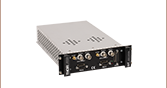
The modular rack chassis is available without a cover (Item # MMR601) for mounting in a standard 19" cabinet or with a cover (Item # MMR602) for benchtop use. Up to six of our four compatible control modules (sold below) can be fitted in this enclosure, allowing up to 12 channel motion control within the footprint of a 4U, 19" rack enclosure.

 Zoom
Zoom- 2-Channel Controller for Driving 3-Phase, Brushless DC Servo Motor Products up to 100 W Peak
- USB and AUX I/O Ports for Communication and Plug-and-Play PC Operation Through the MMR601 or MMR602 Enclosure
- Incremental Encoder Feedback for Closed-Loop Velocity and Position Control
- Motor Control I/O Port (Jogging, Interlocks)
- Supported by the Kinesis Software Control Suite
- Features Supported by Kinesis:
- Fast Position Input/Output Triggering
- Synchronized Moves
- Dynamic PID Settings
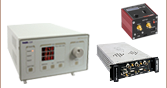
The MBD602 Controller Module is a dual-channel, high-resolution, brushless DC motor driver designed specifically for use with the highly flexible MMR601 or MMR602 Motion Control 19" Modular Rack System. It can drive Thorlabs' range of 3-phase brushless DC servo motors up to 100 W, with or without encoder feedback. With our robust Kinesis software package, fast input and output triggering makes this unit a versatile building block for complex control systems that can be customized to fit diverse application needs.
Up to six MBD602 Controller Modules fit within the modular rack systems sold above, providing a scalable motion control solution for multi-axis motion control applications. Within an MMR601 or MMR602 rack enclosure, multiple modules can be connected to a single PC via standard USB hub technology for multi-axis motion control applications. Coupling this with the user-friendly Kinesis software allows the user to get up and running very quickly. For example, all relevant operating parameters are set automatically for Thorlabs' stage/actuator products. Advanced custom motion control applications and sequences are also possible using the extensive .NET programming environment, which is described in more detail in the Kinesis Software and Kinesis Tutorials tabs.
Triggering Capabilities
The MBD602 controller is equipped with powerful input and output position triggering capabilities. With a latency under 102 µs, the intervals to send live position triggers are user-defined, so the user can set near-encoder level trigger points (down to 100 - 200 nm) for live data capture or feedback. The position trigger engine sends thousands of pulses while scanning, providing the user with a versatile platform for highly customizable image mapping to suit a diverse range of applications. With our Kinesis software, the user can define a start point, interval for pulses, number of pulses, and pulse width of the output trigger. As an example, to image a 5 mm x 5 mm sample, the user can define the edge of the sample and then have the system raster scan across the sample, taking images at any desired interval. With the trigger interval matched to the system's field of view, the images can be digitally combined to efficiently reconstruct a high magnification view of the whole sample.
Optional Joystick
An optional 2-axis joystick (Item # MJC2) is also available for tactile, manual positioning of a stage. See the manuals, found by clicking on the red Docs icons (![]() ), for more information on using the joystick.
), for more information on using the joystick.
Cabling
Cables for connecting actuators or stages to the controller are shipped with the actuators or stages, not the controller. If you need help identifying the appropriate replacement cable, please contact Tech Support.

 Zoom
Zoom- Two Stepper Motor Drive Channels
- High Resolution Microstepping Control (For Very Fine Positioning Applications)
- Stable and Predictable Low-Speed Operation (For Velocity Sensitive Applications)
- Supports 2-Phase Bipolar Steppers up to 48 V / 50 W Peak
- Differential Encoder Feedback (QEP Inputs) for Closed-Loop Positioning
- USB Plug and Play for Multi-Axis Expansion
- Motor Control I/O Port (Jogging, Interlocks)
- Fully Software Integrated with Other Thorlabs Motion Controllers (Integrated Systems Development)
- Compatible with the Kinesis Software Control Suite
The MST602 module is a dual-channel, high-resolution, rack-mounted stepper motor driver designed for use with the MMR601 or MMR602 Motion Control 19" Modular Rack System. It can drive 2-phase bi-polar stepper motors up to 50 W, with or without encoder feedback, and is compatible with the full range of stepper-motor-equipped nanopositioning actuators and stages offered by Thorlabs. Alternatively, it is also compatible with any generic two-phase bi-polar motor of varying powers and varying cardinal step sizes.
When used with a MMR601 or MMR602 Rack Enclosure, this unit can be used with a PC via USB connection. Up to six modules can be mounted in one of these enclosures and connected to a single PC via standard USB hub technology for multi-axis motion control applications. Coupling this with the user-friendly Kinesis software allows the user to get up and running very quickly. Advanced custom motion control applications and sequences are also possible using the extensive programming environment, which is described in more detail in the Kinesis Software and Kinesis Tutorials tabs.
An optional 2-axis joystick (Item # MJC2) is also available below for tactile, manual positioning of a stage. See the manuals, found by clicking on the red Docs icons (![]() ), for more information on using the joystick.
), for more information on using the joystick.
Cabling
Cables for connecting actuators or stages to the controller are shipped with the actuators or stages, not the controller. If you need help identifying the appropriate replacement cable, please contact Tech Support.

 Zoom
Zoom- Two Piezo Drive Channels
- Quiet High-Resolution Position Control (for Very Fine Positioning Applications)
- Voltage Ramp and Waveform Generation Capability (for Scanning Applications)
- High Bandwidth (10 kHz) Piezo Positioning
- Auto-Configure Function for Thorlabs' Identification-Equipped Piezo Actuators
- User Controlled Digital and Analog I/O Port
- Fully Software Integrated with Other Thorlabs Motion Controllers (Integrated Systems Development)
- Compatible with the Kinesis Software Control Suite
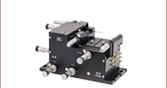
The MPZ601 piezo driver module is a dual-channel, high-power (75 V, 500 mA) piezo controller. It has been designed to drive the full range of open- and closed-loop piezo-equipped nano-positioning actuators and stages offered by Thorlabs. Equipped with strain gauge feedback circuitry on each channel, this unit is able to provide closed-loop positioning in the nanometer regime when operated with Thorlabs' actuators. In addition, flexible software settings make these units highly configurable and therefore suitable for driving a wide range of piezo elements in third party products. A waveform generation capability combined with triggering outputs makes this unit particularly suitable for piezo scanning applications.
This module incorporates the latest high-speed digital signal processing (DSP) and low-noise analog electronics technology and has been designed specifically to fit within the highly flexible MMR601 or MMR602 Motion Control 19" Modular Rack System. Multiple MPZ601 piezo modules can be fitted to this rack system (providing up to 12 channels of operation per rack) to support larger scale critical alignment applications where nanometer level motion control is required with a high axis count.
USB connectivity via the MMR601 or MMR602 Rack Enclosure provides easy plug and play PC operation - multiple modules can be connected to a single PC via standard USB hub technology for multi-axis motion control applications. Coupling this with the user friendly Kinesis software allows the user to very quickly get up and running in a short span of time. Advanced custom motion control applications and sequences are also possible using the extensive programming environment described in more detail in the Kinesis Software and Kinesis Tutorials tabs.
Cabling
Cables for connecting actuators or stages to the controller are shipped with the actuators or stages, not the controller. If you need help identifying the appropriate replacement cable, please contact Tech Support.

 Zoom
Zoom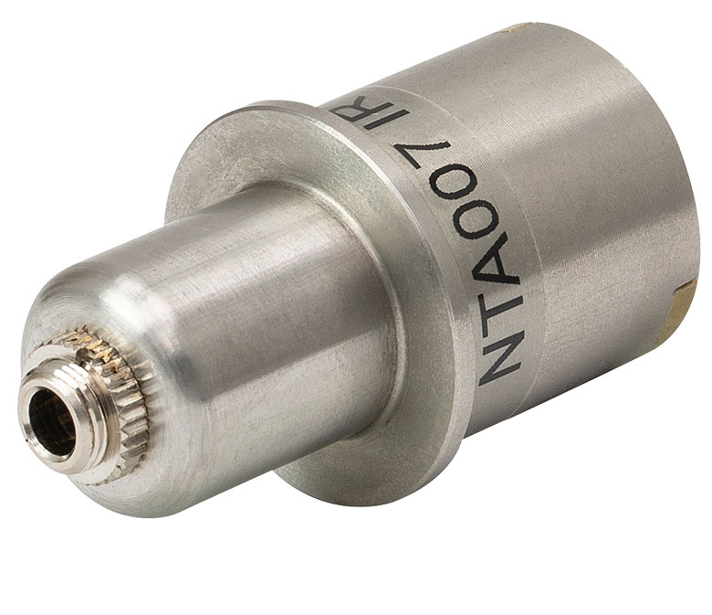 Click to Enlarge
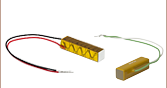
NTA007 Infrared Wavelength Detector, Back View
- Active Alignment System with Advanced Light Search Algorithm
- Tracking Feature Maintains Optimum Throughput Indefinitely
- Latch Mode to Maintain Alignment Stability over Time
- MNA601/IR Module Provides 2-Axis Control
- Two Piezo Actuator Output Channels Provide Closed-Loop Feedback
- IR (InGaAs) Detector (Item # NTA007) & SMB Connector for External Diodes Included
- Visible (Si) Detector (Item # NTA009) Available Separately
- Full Software GUI Control Suite and Support for Third-Party Custom Applications
The modular NanoTrak Auto-Alignment Controller is designed to maximize the coupling power throughput of a fiber-to-fiber or fiber-to-free-space system. By driving a piezo-actuated stage to move the fiber tip in a circular scan pattern, the controller performs a power gradient search to determine the direction of peak power and positions the fiber for maximum throughput. Two high-voltage output channels provide the drive signal for the associated piezo actuators, eliminating the need for external piezo drivers. In combination with a multi-axis, piezo-driven stage, such as our 3-Axis NanoMax and 6-Axis NanoMax stages, a fiber alignment controller creates a complete auto-alignment system.
When used with the MMR601 or MMR602 rack systems, USB connectivity provides easy 'Plug-and-Play' PC-controlled operation with the Kinesis software package, which features .NET controls that can be used by third-party developers working in the latest C, C#, LabVIEW™ or any .NET compatible languages to create custom applications. For more details, please see the Kinesis Software and Kinesis Tutorials tabs.
The initial coupling of light from one device (e.g. fiber) to another involves searching a multidimensional space until a signal is detected. The NanoTrak support software offers a series of motor search algorithms for this first light detection. Although used primarily for aligning optical fibers and integrated optical devices, the NanoTrak is ideal for automating just about any labor intensive alignment tasks such as waveguide characterization, fiber pigtailing of active and passive devices, as well as a multitude of other R&D applications.
Cabling
Cables for connecting actuators or stages to the controller are shipped with the actuators or stages, not the controller. If you need help identifying the appropriate replacement cable, please contact Tech Support.
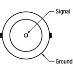
Detector Heads
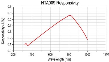
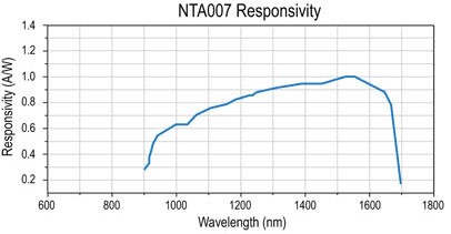
The NanoTrak module is supplied with an InGaAs detector (Item # NTA007) for infrared (900 - 1700 nm) wavelengths and a PIN diode SMB input for use with external detector heads. A Si detector (Item # NTA009) for visible (320 - 1100 nm) wavelengths is available separately below. Both detector heads have an FC/PC optical fiber input and interface with the controller via a jack at the back of the detector, as shown above to the right. The specs and wavelength responsivity of each of these detectors are shown in the table and plot below.
| Item # | Wavelength Range | Active Area | Fiber Input | Dark Current | Junction Capacitance |
|---|---|---|---|---|---|
| NTA009 | 320 - 1000 nm | Ø0.8 mm | FC/PC | 0.01 nA (Typ.) @ 10 V | 3.00 pF (Typ.) @ 10 V |
| NTA007 | 900 - 1700 nm | Ø0.12 mm | FC/PC | 0.05 nA (Typ.) @ 5 V | 2.0 pF (Typ.) @ 5 V |