 Products Home / Fiber Fusion Splicers and Processing Equipment / Fiber Recoaters / Replacement Components for Vytran® Fiber Recoaters with UV Curing Lamps
Replacement Components for Vytran® Fiber Recoaters with UV Curing Lamps
- Compatible with our Previous-Generation Fiber Recoaters with UV Halogen Bulbs
- Mold Assemblies with Three Available Coating Diameters
- Replacement Injectors, Tubes, Fiber Block Inserts,
and Handset Controllers
VHJ500
Bottom Fiber Block Insert
PC373
Low-Index Recoat Material
RM430A
Mold Assembly for Manual Recoater,
50 mm Max Recoat Length
PTRRRM
Replacement Manual Injector
for 50 mm Recoaters
VHH000
Top Fiber Block Insert


Please Wait
Click to Enlarge
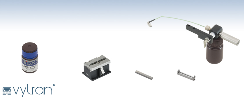
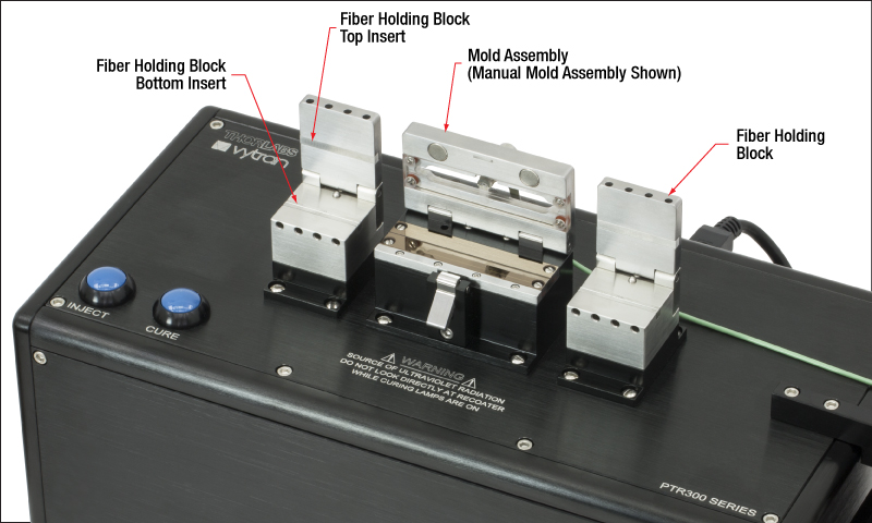
Figure 1.1 Thorlabs' Fiber Recoater Indicating the Mold Assembly, Fiber Holding Blocks, and Fiber Holding Block Inserts
Features
- Mold Assemblies with Three Available Coating Diameters
- Fiber Holding Block Inserts Compatible with Linear and Rotary Proof Testers
- High-Index and Low-Index Recoat Materials
- Replacement Manual Injectors, Injection Tubes, and Handset Controllers
Thorlabs offers these mold assemblies, fiber holding block inserts, and recoat materials that are compatible with our previous-generation Vytran® Fiber Recoaters with UV Curing Lamps. These replacement items are provided for customers with previous-generation PTR303(B), PTR304(B), PTR306(B), and PTR307(B) units.
New customers are encouraged to consider one of our fiber recoaters with UV curing LEDs. Upgrades to UV LEDs may be available for owners of previous-generation units; please contact Tech Support for more information.
Mold Assemblies
Our mold assemblies are available in a variety of sizes so that customers can choose the right mold coating diameter for their application. Custom mold coating sizes are available up to Ø900 µm. Please contact Tech Support for more information on custom molds.
Inserts for Fiber Holding Blocks
We offer a variety of fiber holding block inserts in order to support a wide range of fiber coating diameters. The inserts cover fiber coatings from Ø80 µm to Ø1000 µm; a total of four are necessary for each recoater, two top inserts and two bottom inserts.
Recoat Materials
Thorlabs offers both high-index (Item # AB950200) and low-index (Item # PC373) recoat materials. Previous-generation recoaters with manual injection pumps (Item #s PTR303B, PTR304B, PTR306B, and PTR307B) are compatible with both types of recoat material. Manual recoaters with an automatic injection system (Item #s PTR303, PTR304, PTR306, and PTR307) are compatible with the high-index recoat material, but they may be customized to work with both the low- and high-index recoat material. Please contact Tech Support for more information.
| Posted Comments: | |
user
(posted 2019-04-18 06:55:32.927) 1.Do you provide any test report for recoater unit? [eg., by including results of two recoatings of a fiber (one HI and one LI acrylate) such as adhesion, tension etc., If not what else (certificate of compliance etc.,) do you provide confirming quality of the product
2.For manual recoat injector ( PTR 303B), how can user programme inject rate, inject amount? These parameters are controlled by manual operation of injector eg., by pressure applied (manually) on syringe piston.
3. Do you provide installation service in India? If so what is additional cost of installation/demonstration? nbayconich
(posted 2019-04-25 04:56:03.0) Thank you for contacting Thorlabs. The PTR303B can be easily programmed by the user to change the injection qty, injection rate, fiber diameter used, etc using the tablet & software provided.
We have regional Vytran reps that can help provide on site work at your location. A Vytran representative will contact you directly with more information regarding our recoater's testing documentation and services. |
The table below outlines the entire PTR series to directly compare the capabilities across the whole line.
| Vytran® PTR Series Recoater and Proof Tester Selection Guide | ||||||||
|---|---|---|---|---|---|---|---|---|
| Item # | UV Curing Source | Mold Assembly | Proof Tester | Recoat Injection Pump | Max Recoat Length | Recoat Material | Mold Cleaning Requirement | |
| High Index (Item # AB950200) |
Low Index (Item # PC373) |
|||||||
| Dedicated Proof Testers | ||||||||
| PTR301 | N/A | N/A | Linear | N/A | N/A | - | - | N/A |
| PTR302 | Rotary | - | - | |||||
| Dedicated Recoatersa | ||||||||
| PTR403 | LEDs | Manual | N/A | Automatic | 50 mm | - | After Every Recoat Process | |
| PTR403B | Manual | 50 mm | ||||||
| PTR404B | Manual | 100 mm | ||||||
| PTR305 | LEDs | Automatic | N/A | Automatic | 50 mm | - | Dailyb | |
| Recoaters with Proof Testersa | ||||||||
| PTR406 | LEDs | Manual | Linear | Automatic | 50 mm | - | After Every Recoat Process | |
| PTR406B | Manual | 50 mm | ||||||
| PTR407 | LEDs | Manual | Rotary | Automatic | 50 mm | - | After Every Recoat Process | |
| PTR407B | Manual | 50 mm | ||||||
| PTR308 | LEDs | Automatic | Linear | Automatic | 50 mm | - | Dailyb | |

 Zoom
Zoom| Item # | Coating Diameter |
Max Recoat Length |
Compatible Recoatersa |
|---|---|---|---|
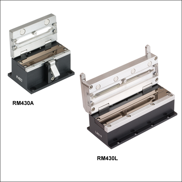
| RM280A | 280 µm | 50 mm | PTR303(B), PTR306(B), PTR307(B) |
| RM430A | 430 µm | ||
| RM600A | 600 µm | ||
| RM280L | 280 µm | 100 mm | PTR304(B) |
| RM430L | 430 µm | ||
| RM600L | 600 µm |
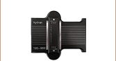
- Compatible with Previous-Generation UV Lamp Fiber Recoaters
- Three Available Mold Coating Diameters: 280 µm, 430 µm, and 600 µm
- 50 mm or 100 mm Maximum Recoat Length
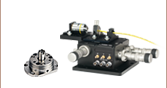
The Mold Assemblies are composed of split quartz mold plates which, when closed, form the cylindrical mold cavity around the exposed section of the fiber being recoated. They are available for Ø280 µm, Ø430 µm, or Ø600 µm fiber coatings and in maximum fiber recoat lengths of 50 mm and 100 mm. Custom mold sizes up to Ø900 µm are available; please contact Tech Support for more information. Mold assemblies with a 50 mm recoat length feature a lever to assist with opening or closing the mold.
Recoat material (sold below) is injected into the mold assembly by either an automatic or manual injection system. Then, UV light cures the recoat material. Cure times are dependent on the mold size and recoat material, but they range from approximately 12 - 15 seconds for the RM280A mold assembly with high-index AB950200 recoat material to 30 - 60 seconds with the low-index PC373 recoat material. The recoater mold assembly should be cleaned throughly with isopropyl alcohol or acetone between each recoating process; reliable and repeatable performance is highly dependent on the cleanliness of the mold.
When purchasing a manual fiber recoater for the first time, it is necessary to choose a mold assembly that is appropriate for the desired fiber coating diameter. Additional mold assemblies may also be purchased and swapped out by the user. The assembly simply screws to the top of the device, making the removal and install simple and easy. Because of this, our manual recoaters are adaptable and flexible in the field and can be modified to accept varying diameters of fiber quickly. A recoater mold can be factory installed prior to shipment upon request by contacting Tech Support. It is also necessary to order the proper inserts (sold below) that best match the fiber diameter being used, whether purchasing a fiber recoater for the first time or updating a current recoater for a different fiber diameter.

 Zoom
Zoom| Compatible Fiber Buffer/Coating Diameters & Recoaters | |||||
|---|---|---|---|---|---|
| Item # | Top or Bottom |
Nominal Diameter |
Min Diameter |
Max Diameter |
Compatible Recoaters |
| VHJT | Top | - | 80 µm | 700 µm | PTR306(B)b |
| VHJT900a | Top | 900 μm | 700 µm | 1000 µm | |
| VHJ250 | Bottom | 250 μm | 80 µm | 375 µm | |
| VHJ500 | Bottom | 500 μm | 375 µm | 700 µm | |
| VHJ900Sa | Bottom | 900 μm | 700 µm | 1000 µm | |
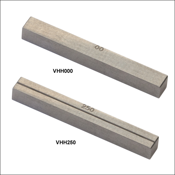
| VHH000 | Top | - | 90 µm | 660 µm | PTR305 PTR303(B)b PTR304(B)b PTR307(B)b |
| VHH900a | Top | 900 µm | 700 µm | 1000 µm | |
| VHH100 | Bottom | 100 µm | 90 µm | 110 µm | |
| VHH125 | Bottom | 125 µm | 113 µm | 137 µm | |
| VHH160 | Bottom | 160 µm | 144 µm | 176 µm | |
| VHH250 | Bottom | 250 µm | 225 µm | 275 µm | |
| VHH300 | Bottom | 300 µm | 250 µm | 350 µm | |
| VHH400 | Bottom | 400 µm | 350 µm | 450 µm | |
| VHH500 | Bottom | 500 µm | 450 µm | 550 µm | |
| VHH600 | Bottom | 600 µm | 540 µm | 660 µm | |
| VHH900Sa | Bottom | 900 µm | 810 µm | 990 µm | |
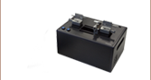
- Fiber Block Inserts for Thorlabs' Fiber Recoaters
- Two Types:
- VHJ Series for Recoaters with Linear Proof Testers
- VHH Series for Recoaters with Rotary Proof Testers
- Compatible with Fiber Coating Diameters from 80 µm to 1000 µm
- Choose Two Top Inserts and Two Bottom Inserts
A total of four inserts, two top inserts and two bottom inserts, are required for a full recoater unit. The inserts are seated in and secured to the fiber holding blocks. They can easily be swapped out for different sizes, allowing our recoaters to adapt quickly should different fiber coating sizes be desired. These inserts are compatible with fiber coatings ranging from Ø80 µm to Ø1000 µm.
We offer two types of inserts. The VHJ Series inserts are designed for recoaters with linear proof testers (Item #s PTR306 and PTR306B). The VHH Series inserts are are designed for recoaters with a rotary proof tester (Item #s PTR303, PTR303B, PTR304, PTR304B, PTR305, PTR307 and PTR307B).
Custom sizes are available; please contact Tech Support for more information.

 Zoom
Zoom| Item # | Recoat Material | Compatible Recoaters | |
|---|---|---|---|
| Automatic Injection | Manual Injection | ||
| AB950200 | High Index | PTR303a, PTR304a, PTR306a, PTR307a, PTR305, PTR308, PTR403, PTR404, PTR406, PTR407 |
PTR303Ba, PTR304Ba, PTR306Ba, PTR307Ba, PTR403B, PTR404B, PTR406B, PTR407B |
| PC373 | Low Index | - | |
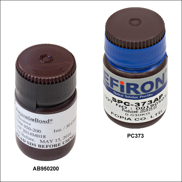
- AB950200: High-Index Recoat Material
- PC373: Low-Index Recoat Material
Thorlabs offers UV-curable acrylate recoat materials to be used in our PTR series fiber recoaters. We offer both high-index (Item # AB950200) and low-index (Item # PC373) material in 1 oz bottles. The high-index material can be used in all recoaters (except the PRL201), whereas the low-index material can only be used in recoaters with the manual injection pump option.

 Zoom
Zoom| Table 604A Specifications | |||
|---|---|---|---|
| Item # | Component Description |
Compatible Recoaters | |
| 50 mm Recoaters | 100 mm Recoaters | ||
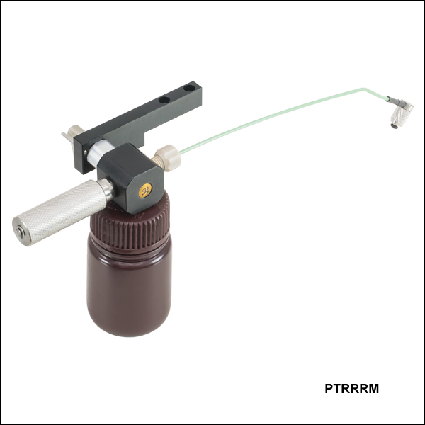
| PTRRRM |
Manual Injector | PTR303Ba, PTR306Ba, PTR307Ba, PTR406B, PTR407B |
- |
| PTRRRML |
- | PTR304Ba, PTR404B | |
| RRMTA |
Injection Tube | PTR303Ba, PTR306Ba, PTR307Ba, PTR406B, PTR407B |
- |
| RRMTAL | - | PTR304Ba, PTR404B | |
| RRMS | Syringe Barrel | PTR303Ba, PTR306Ba, PTR307Ba, PTR406B, PTR407B |
PTR304Ba, PTR404B |
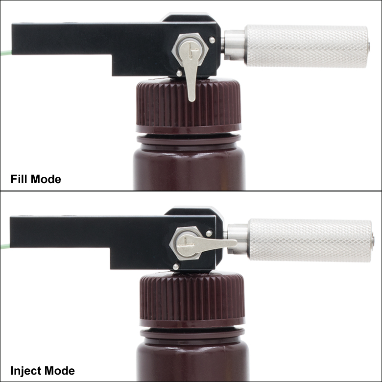
Click to Enlarge
Figure 604C Manual Injector Lever Positions for Fill and Inject Modes

Click to Enlarge
Figure 604B The manual injector is mounted to the recoater via two 4-40 mounting screws.
- Replacement Manual Injectors for Dispensing Recoat Material into the Mold
- Accept PC373 and AB950200 Recoat Materials
- Replacement Injection Tubes for Recoaters with Manual Injectors
- Replacement Syringe Barrel for Manual Injectors
These manual injectors and injection tubes are available as replacement parts for Thorlabs' Vytran Fiber Recoaters with Manual Injectors; compatible systems are listed in Table 604A. We also offer a replacement syringe barrel.
Each injector can be mounted to compatible fiber recoaters via two 4-40, 3/32" hex screws on the recoater housing (see Figure 604B). To connect the injector to the recoater mold, tighten the connector at the end of the green plastic tubing, then loosen by a 1/4 turn to allow for rotation.
The injector is equipped with a distribution valve and two-position selection lever for directing the flow of recoat material. A knurled dispensing screw with an internal plunger acts as a syringe for the recoat material. To fill the syringe, point the lever downward (i.e., toward the recoat bottle), then rotate the knurled dispensing screw counterclockwise until it spins freely to fill the syringe (shown in Figure 604C). Then, to inject the recoat material into the mold, point the lever horizontally (i.e., facing the knurled screw) and rotate the screw clockwise until near the end of the travel range is reached. Avoid bottoming out the dispenser as this may damage the internal plunger; also take care when re-engaging the threads to avoid cross threading the dispensing screw. Several fill/inject steps may be needed until air is displaced within the system. Use lens tissue and an acetone or alcohol cleaning solution to collect any excess recoat material that flows from the mold.
Each injection tube and the RRMS syringe barrel are available as replacement parts for the manual injectors. The injection tube should be changed out if the knurl fitting breaks off the end, it leaks recoat material, or a clog forms that cannot be cleared with acetone. If the syringe no longer injects or an excessive number of air bubbles are visible in the recoat material (even after flushing the system), the syringe barrel should be replaced. A 5/16" thin spanner wrench is required for securing the syringe onto the recoat injector. Detailed installation instructions are provided in the support documentation, which can be found by clicking on the red documents icon (![]() ) next to each item number.
) next to each item number.

 Zoom
ZoomCompatible Systems
- PTR303*, PTR304*, and PTR403 Manual Fiber Recoaters, Automatic Recoat Injector
- PTR306*, PTR307*, PTR406, and PTR407 Manual Fiber Recoaters with Proof Testers, Automatic Recoat Injector
*These previous-generation items are no longer available for purchase.
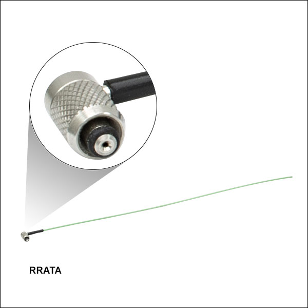
- Replacement Injection Tube for Dispensing Recoat Material into the Mold
- Compatible with Vytran Fiber Recoaters with Manual Mold Assemblies that Use Automatic Injectors (See List of Compatible Systems)
- For Use with AB950200 and PC373 Recoat Materials
This replacement injection tube is compatible with Thorlabs' Vytran Fiber Recoaters that use Manual Mold Assemblies and Automatic Injection Systems (see list of Compatible Systems). Though each system comes with an injection tube installed, it may need to be replaced if the knurled fitting breaks off the end, it leaks recoat material, or a clog forms that cannot be cleared with acetone.
Detailed installation instructions for the RRATA injection tube are provided in the support documentation, which can be found by clicking on the red documents icon (![]() ) next to the item number.
) next to the item number.

 Zoom
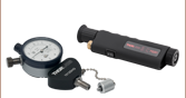
ZoomCompatible Systems
- PTR302 Fiber Rotary Proof Tester
- PTR307(B)* and PTR407(B) Manual Fiber Recoaters with Proof Testers
- FFS2001PT Fiber Preparation and Splicing Workstation
- FFS2001WS Fiber Preparation, Splicing, and Proof Testing Workstation
*These previous-generation items are no longer available for purchase.
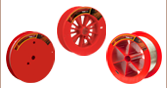
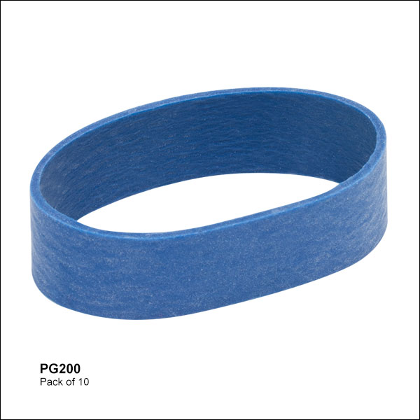
The PG200 Proof Test Grips are designed as replacements for the Vytran rotary proof testers (see list of Compatible Systems). Each system is sold with a set of these grips installed.
Proof test grips may need to be replaced when the fiber slips at high tension levels. After the proof test grips are replaced the system will need to be calibrated; please contact Tech Support for details. Instructions for replacing the proof test grips are provided in each system's manual.

 Zoom
Zoom
Click for Details
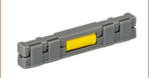
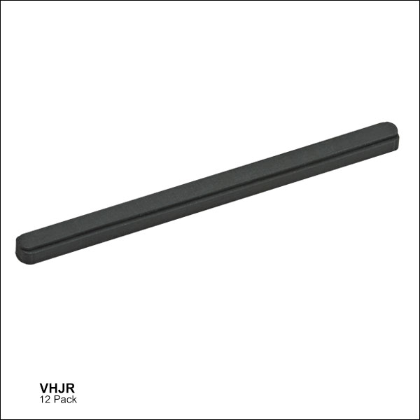
Figure 705A VHJR Rubber Strip shown partially inserted into the metal channel of a VHJT Fiber Holding Block Insert.
- Replacement Rubber Strip for VHJT, VHJ250, and VHJ500 Fiber Holding Block Inserts
- 2" Length (Trim to Size)
- Available in a Pack of 12
This 12 Pack of Replacement Rubber Strips is directly compatible with our VHJT, VHJ250, and VHJ500 fiber holding block inserts. Although one rubber strip comes preinstalled in each insert, these can wear out over time and should be replaced when the holding block insert no longer withstands the applied proof test tension.
The rubber strip features a raised profile, and care must be taken during installation to ensure this profile sits above the metal channel of the insert. Detailed installation instructions are provided in the VHJR support documentation, which can be found by clicking on the red documents icon (![]() ) next to the item number.
) next to the item number.

 Zoom
Zoom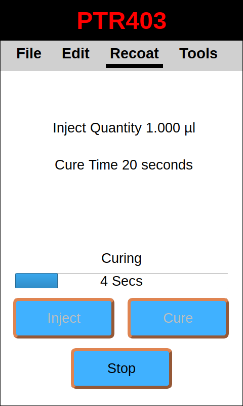
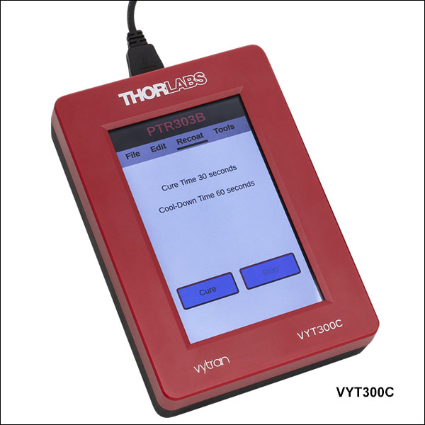
Click to Enlarge
Figure 681A Screenshot of VYT300C Controller When Used with PTR403 Recoater
Compatible Systems
- LDC401(A) Fiber Cleavers
- LDC450B Portable Fiber Cleaver
- PTR303(B), PTR304(B), PTR306(B), PTR307(B), PTR403(B), PTR404B, PTR406(B), and PTR407(B) Manual Mold Fiber Recoaters
- PTR305 and PTR308 Automatic Mold Fiber Recoaters
- PTR301 and PTR302 Fiber Proof Tester
- Provides Full Functionality for Compatible Systems (See List of Compatible Systems)
- Intuitive GUI
- Capacitive Touchscreen
- Small Footprint
This handset controller is available as an alternative to the tablet controller previously included with our Vytran Large Diameter Fiber Cleavers, PTR Series Fiber Recoaters, and PTR Series Fiber Proof Testers. One handset controller is included with each new PTR series recoater system. A single handset controller can be used with multiple systems; after configuring parameters for one fiber processing unit, the controller can be disconnected and then connected to a different unit, of the same or a different type, to configure its parameters.
The handset controller must be connected via the included cable in order to use it. The controller automatically turns on when the connected system is turned on. Upon startup, the handset controller will always read parameters from the connected system; i.e., the parameters that appear on the screen will always be the parameters that have been uploaded to the connected unit. If the parameters read from the unit match the parameters of the most recently opened file on the handset controller, the screen will display the file name.
The suite of tools available through the handset controller includes a record of the total cure time of the machine (under Process Counters) that is not shown on the tablet controller. This value may be reset each time the bulbs are replaced.
The handset controller can open, save, delete, export, and import files containing parameters for compatible systems. Exporting or importing a file will require a memory device to be connected to the Program Port of the handset controller.
Instructions for using this controller can be found in the manuals for the compatible Vytran systems.