 Products Home / Fiber Fusion Splicers and Processing Equipment / Fusion Splicers / Vytran® Fiber Preparation, Splicing, and Proof Testing: SM, MM, and PM
Vytran® Fiber Preparation, Splicing, and Proof Testing: SM, MM, and PM
- Prepare and Splice SM, MM, or PM Fibers with Cladding Diameters from 80 µm to 200 µm
- Includes Proof Testing Capability
FFS2001WS
Shown with Recoat Mold Assembly (Purchased Separately)
RM280UV
Recoat Mold Assembly
Base Unit and Components Sold Separately
FTV7
Tungsten Fusion Splicing Filament
CST080180
Thermo-Mechanical Stripping Blade Insert Set


Please Wait
Building a Complete Fiber Processing System?
To build a complete system, you will need to purchase a base unit plus additional components that are dependent upon the size of the fiber being processed. We recommend that you contact us prior to ordering for assistance with choosing a system and all the necessary components. This also allows us to install and factory-align all system components within the base unit prior to shipping, ensuring optimal performance out-of-the-box.
To take advantage of this assistance, please e-mail us directly at techsupport@thorlabs.com and a representative will contact you shortly.
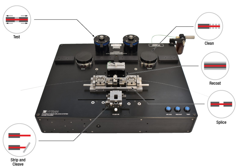
The Process for Fusion Splicing
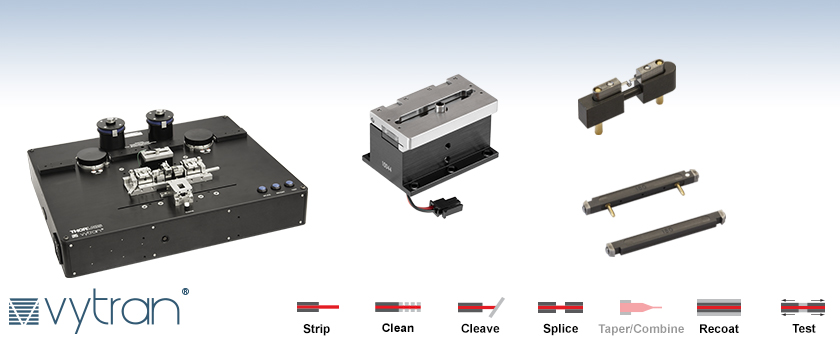
The FFS2001WS Incorporates All Components and Procedures to Prepare the Fiber for Splicing:
- A Coating Soaking Station for Specific Fibers that Require a Solvent Pre-Soak to Soften the Coating Prior to Stripping
- A Thermo-Mechanical Stripping (TMS) Station Provides a Fast, Single-Step Process for Safely Removing Acrylate Coatings while Maintaining Fiber Strength
- Ultrasonic Fiber Cleaning Removes Coating Particles or Residue Left on the Glass Surface that Could Reduce Splice Strength
- An Automatic Fiber Cleaver Produces a Flat Cleave, Important for Achieving Low-Loss Splices
- Uniquely Designed Fiber Holding Blocks and Transfer Jig Minimize Fiber Handling by Precisely Positioning the Fibers for Each Process
- Omega-Shaped Filament Provides a Uniform Concentric Heat Source for Fusing the Fiber Tips, as well as for an Optional Post-Fusion Fire Polishing Step to Remove Silica Deposits
- Recoater Restores the Protective Polymer Coating Over the Spliced Region
- Rotary Proof Tester Qualifies the Strength of the Splice
See the Tutorial Videos tab for demonstrations of these features.
The video above shows the functionality of our legacy FFS2000WS fiber workstation. This functionality is the same as for the FFS2001WS sold below.
Features
- Fiber Coating Soaking Station
- Thermo-Mechanical Coating Stripping Station
- Ultrasonic Fiber Cleaning Station
- Fiber Cleaving Station Provides Flat Cleaves (Replacement Blades Available Below)
- Automatic Fiber Alignment and Accurate Splice Loss Determination
- Automatic 4-Axis Positioning System for PM Rotation
- Filament Fusion Splicing Station with Automatic Post-Fusion Fire Polishing for Strength Enhancement
- Recoat Station for Acrylate Coating Restoration
- Built-in Proof Tester / Tension Tester
- Includes Windows® 10 PC with GUI
- Replacement Components Sold Separately Below
Thorlabs' Vytran® All-in-One Fiber Preparation and Fusion Splicing Workstation offers all fusion splicing and cleaving procedures integrated into a single benchtop system that can be used to produce consistent splices quickly and efficiently (US Patent: 9,977,189). This workstation uses our filament fusion technology to provide a convenient, reliable method of making high-strength, low-loss splices for both production and R&D applications. The splicer features True Core Imaging technology, which is a high-magnification, high-resolution optical imaging system capable of detecting and displaying the inner core structure of a fiber. This technology provides for fast, accurate core alignment and splice loss calculation. Also included is a Windows® 10 PC with a user interface that offers complete configuration and process control. The model offered here includes rotational alignment for PM fibers and a proof / tension tester.
The system is capable of processing fibers with Ø80 µm to Ø200 µm cladding. This includes standard Ø80 µm cladding / Ø180 µm coating and Ø125 µm cladding / Ø250 µm coating fibers.
Automatic Alignment
Our FFS2001WS All-in-One Workstation detects and displays a fiber's inner core structure; in conjunction with 0.01 µm resolution stepper-motor-controlled XY positioners, the FFS2001WS provides a fast and accurate alignment system. Alternately, the stepper motors in the FFS2001WS can also interface with external test and measurement equipment, such as power meters, spectrum analyzers, and polarimeters, through analog BNC inputs, to create a fully automated optical assembly station.
The workstation can also provide a splice loss determination after the splicing is complete. From the image of the fiber cores, a proprietary algorithm is used to accurately calculate the loss for a splice of a variety of similar or dissimilar fiber types.
Filament Fusion
Our unique filament fusion technology provides a consistent, reliable method of making high-strength, low-loss splices. Precise control of the fusion process is achieved by purging the splice region with an inert gas and using a tungsten or iridium filament to supply the thermal input necessary for fiber fusion. Because the fusion heat source is isolated from the environment, filament fusion splicing is not dependent on ambient conditions. Controlled conditions inside the system in combination with constant power control circuitry ensure repeatable performance splice after splice.
Fire Polishing
Our fire polishing process significantly increases splice strength through a rapid post-fusion heat treatment of the splice region. When a fusion splice is made, silica will evaporate off of the hot center region of the splice and condense on either side of the joint where the fiber is cooler. The condensed silica deposits act as a surface flaw, lowering splice strength. The fire polishing process removes or minimizes the deposits, thereby improving splice strength. In addition, the fire polishing process provides capabilities to expand adiabatically the mode field diameter of a fiber by causing the dopants in the cladding to diffuse farther from the core. Through this thermal core expansion process, extremely low-loss fusion splices between markedly dissimilar fibers, such as those typically used in WDM applications, can be achieved.
Recoating
The FFS2001WS includes an optical fiber recoater to restore the protective polymer coating over the fusion splice. The combination of high-strength filament fusion splicing and UV acrylate recoating provides a more reliable alternative to standard heat shrink protection sleeves. The recoat process maintains a near-original fiber diameter and delivers a smooth, flexible fusion splice that can be handled or tightly coiled as if no splice were present.
Proof Testing
The FFS2001WS includes a rotary proof tester that can test fibers up to a tension of 89 N (20 lbs) with an accuracy of ±2%. The included software allows the user to program the unit to perform either a tension test, where the splice is tested to failure, or a proof test, where it is tested to a pre-determined tension. One set of proof test grips is included; replacement proof test grips are available below in packs of 10.
| All-In-One Fiber Processing Workstation Selection Guide | |||
|---|---|---|---|
| SM and MM Fiber | SM and MM Fiber with Proof Testing | SM, MM, and PM Fiber | SM, MM, and PM Fiber with Proof Testing |
| Item # | FFS2001WS |
|---|---|
| Accepted Fiber Cladding Diameters | 80 to 200 µm |
| Fiber Type | SM, MM, or PM |
| Thermo-Mechanical Stripper | |
| Accepted Coating Materials | Single or Dual Acrylate |
| Maximum Stripping Temperature | ~130 °F (54 °C) |
| Ultrasonic Cleaner | |
| Accepted Cleaning Solvents | Acetone or Isopropyl Alcohol |
| Cleaning Time | 1 to 120 s |
| Cleaver | |
| Cleave Method | Tension and Scribe (Replacement Blade Item # ACL83, Available Below) |
| Cleave Type | Flat (0°) |
| Maximum Tensiona | 2.45 N (0.55 lbs) |
| Splicing | |
| Fusion Method | Filament Fusion |
| Filament Power | 40 W (Max) |
| Alignment Method | Fully Automated by True Core Imaging® or External Feedback |
| XY Fiber Positioning Resolution | Stepper Motor Controlled with 0.01 µm Resolution |
| Z Fiber Feed Resolution | Stepper Motor Controlled with 0.125 µm Resolution |
| Insertion Loss (SMF to SMF) | 0.02 dB (Typical) |
| Tensile Strength | >250 kpsi (Typical) |
| PM Rotation Specifications | |
| Rotation Alignment | Fully Automated by End-View Alignment Technology or External Feedback |
| Rotation Resolution | Stepper Motor Controller (0.01° Resolution) |
| Rotation Travel | 190° |
| Extinction Ratio | -35 dB (Typical) |
| Recoating | |
| Recoat Mold | Quartz |
| Recoat Diameterb | Ø280 µm, Ø430 µm, or Ø600 µm |
| UV Source | Fourteen UV LEDs |
| Proof Testing | |
| Maximum Tensionc | 89 N (20 lbs) |
| Mandrel Size | Ø2" (Ø50.8 mm) |
| Accuracy | ±2% |
| General Specifications | |
| Size (L x W x H) | 17.00" x 14.00" x 5.30" (431.8 mm x 355.5 mm x 134.7 mm) |
| Weight | 26 lbs (11.8 kg) |
| Power | 12 V DC External Power Supply with Universal AC Input |
| Operating System | Included Windows® 10 PC with Software GUI Installed |
Click to Enlarge
Legacy FFS2000WS with Working Areas Highlighted
Tutorial Videos
Introduction
The FFS2001 All-in-One Fiber Workstations provide users with a system that can perform all the necessary steps to process a fiber: stripping, cleaning, cleaving, splicing, and recoating. Our FFS2001PT and FFS2001WS systems come with a proof testing station to qualify newly processed fiber. For polarization-maintaining or structured fiber processing, our FFS2001PM and FFS2001WS workstations feature rotary fiber holding blocks for aligning structured fibers before a splice. The splicing station contains an omega-shaped filament that will require regular maintenance to guarantee consistent performance.
| Item # | Strip |
Clean |
Cleave |
SM and MM Splice |
PM Splice |
Recoat |
Test |
|---|---|---|---|---|---|---|---|
| FFS2001 | - | - | |||||
| FFS2001PM | - | ||||||
| FFS2001PT | - | ||||||
| FFS2001WS |
| Quick Links | Setup | Filament Maintenance | Software Introduction | Processing |
 Product DemonstrationsThorlabs has demonstration facilities for the Vytran® fiber glass processing systems offered on this page within our Morganville, New Jersey; Shanghai, China; and Exeter, Devonshire offices. We invite you to schedule a visit to see these products in operation and to discuss the various options with a fiber processing specialist. Please schedule a demonstration at one of our locations below by contacting technical support. We welcome the opportunity for personal interaction during your visit! Thorlabs Vytran Europe
|

.jpg)
| Posted Comments: | |
David Panak
(posted 2023-10-16 07:53:23.153) Does Vytran have a "black box" option for fiber splicing parameters? This would be in the situation that a supplier wished to protect proprietary methods for field splices.
If not, can this option be provided?
thank you cdolbashian
(posted 2023-11-08 12:15:24.0) Thank you for reaching out to us with this inquiry! We do not have this type of option set up by default, but we have contacted you directly in order to create this functionality for your particular application. |
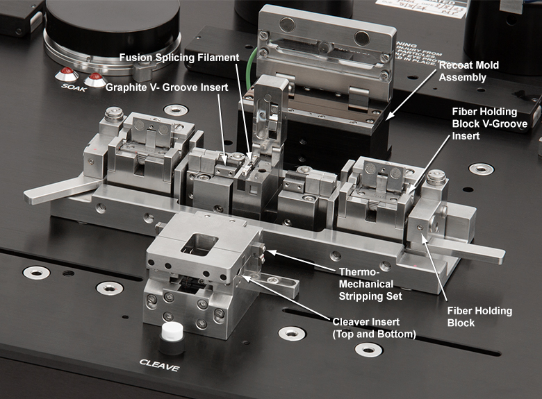
Click to Enlarge
The locations of components that can be purchased separately are labeled in the schematic above and are available for purchase below. The unit ships with a FTV7 Filament and two VHG125 V-Grooves; replacement filaments and v-grooves are available below. For more details on this kit, please see the list to the left.
To begin the process of purchasing your complete fiber preparation and fusion splicing workstation, add the Item # FFS2001WS to your cart. In the subsequent product groupings, you will select one or more required accessories; the number of items required from each group will be indicated in the red headings. The specific choice of components will depend upon your fiber size and type. Once we receive your order, we will review it and contact you if we have any additional questions or if a required component is missing.
As the alignment of the components in the FFS2001WS workstation is critical and must be performed in the factory, your complete system will ship with all of the components installed. Once you receive the system, most inserts (except the Graphite V-Groove Inserts) can be easily replaced by the user if needed. One FTV7 Tungsten Filament and two VHG Graphite V-Grooves (for Ø80 µm - Ø125 µm cladding) come pre-installed in the system. If a different filament or graphite v-groove is needed (see below for additional options), contact Tech Support when purchasing to request a substitution.
An external supply of argon and soaking and cleaning solvents must be provided by the user to operate the workstation.
Please contact Tech Support if you have any questions or would like assistance in building a fiber processing solution to meet your needs. In addition, installation and training by one of our application engineers is recommended for this system; please contact tech support for more details.
Components Included
- FFS2001WS Base Unit
- One FTV7 Tungsten Filament Installed
- Two VHG125 Graphite V-Grooves
(Ø80 - Ø125 µm Cladding) Installed - FHBR1 Fiber Holding Blocks
- Fiber Holding Block Transfer Jig
- Location-Specific Power Supply
and AC Power Cord - PC with Monitor, Keyboard, and Mouse
- Large Tank Regulator with Gas Line
(For Argon Gas Supply) - External Vacuum Pump
- Tool Kit
Must Be Purchased Separately
- V-Groove Inserts for Fiber Holding Blocks
(Two Required) - Thermo-Mechanical Stripper Blade Sets
(One Required) - Bottom Cleaver Inserts (Two Required)
- Top Cleaver Inserts (Two Required)
- Mold Assembly for Recoater (One Required)
- Recoat Materials (One Required)
- >99.999% Purity Argon Gas
(Not Available from Thorlabs) - Soaking and Cleaning Solvents
(Not Available from Thorlabs)
Optional Accessories
- Additional Graphite V-Groove Inserts
- Additional Fusion Splicing Filaments

 Zoom
Zoom| Compatible Fiber Buffer/Coating Diameters | |||
|---|---|---|---|
| Item # | Nominal Diameter | Minimum Diameter | Maximum Diameter |
| VHN100 | 100 µm | 90 µm | 110 µm |
| VHN125 | 125 µm | 113 µm | 137 µm |
| VHN135 | 135 µm | 130 µm | 145 µm |
| VHN160 | 160 µm | 144 µm | 176 µm |
| VHN200 | 200 µm | 180 µm | 220 µm |
| VHN250 | 250 µm | 225 µm | 275 µm |
| VHN300 | 300 µm | 270 µm | 330 µm |
| VHN400 | 400 µm | 360 µm | 440 µm |
| VHN500 | 500 µm | 450 µm | 550 µm |
| VHN600 | 600 µm | 540 µm | 660 µm |
| VHN700 | 700 µm | 630 µm | 770 µm |
| VHN800 | 800 µm | 720 µm | 880 µm |
| VHN900 | 900 µm | 810 µm | 990 µm |
- V-Groove Inserts Align Fibers within the Fiber Holding Blocks Included with the Workstation Base Unit
- Support Buffer or Coating Diameters Ranging from 90 µm to 990 µm
- Two Required: One Each for Left and Right Holding Blocks
These inserts are designed for the FHBR1 Rotating Fiber Holding Blocks that are included with the workstation base unit. A total of two items must be purchased, one insert for the left holding block and one insert for the right holding block. They are provided individually so as to allow for the construction of a system that can process two fibers with different coating diameters. Different V-groove sizes are provided to support a range of fiber coating diameters; compatibility is listed in the table to the right.
When purchased with a workstation base unit, the inserts can be installed at the factory upon request by contacting Tech Support. If necessary, the V-groove inserts can be replaced by the user.

 Zoom
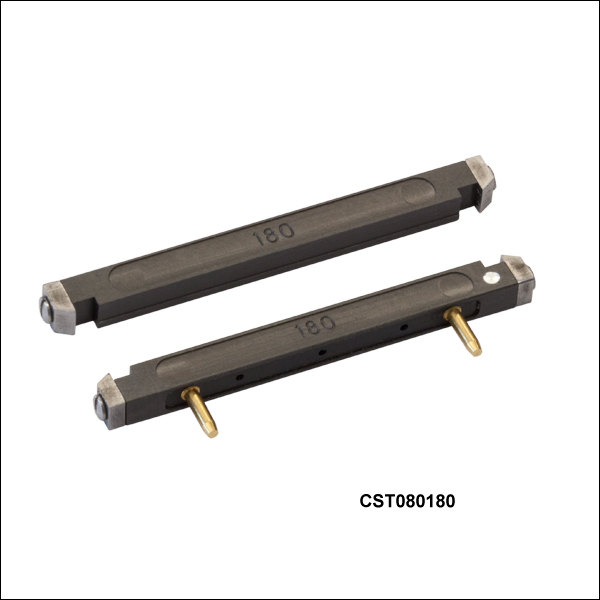
Zoom| Thermo-Mechanical Stripping Blade Insert Sets | |||
|---|---|---|---|
| Item # | Accepted Cladding Diametera | Maximum Buffer Diameter | |
| End 1 | End 2 | ||
| CST080180 | 80 µm | 80 µm | 180 µm |
| CSTM080125 | 80 µm | 125 µm | 250 µm |
| CST125250 | 125 µm | 125 µm | 250 µm |
| CST125400 | 125 µm | 125 µm | 400 µm |
- Thermo-Mechanical Stripping (TMS) Insert Sets for the All-In-One Fiber Preparation and Splicing Workstation
- Each Blade Set Consists of One Top and One Bottom Insert
- Four Sizes Available (See Table to the Right)
Thorlabs offers four sets of blades for stripping fiber. The maximum buffer diameter is limited by the size of the channel in the insert. Each blade set consists of two pieces: one top and one bottom insert that each have flat blades on the ends.
Three of the blades sets are designed to strip the same size cladding on both the left and right ends. The CSTM080125 blade set is designed to strip Ø80 µm cladding fiber on one end and Ø125 µm cladding fiber on the other. When ordered with the workstation base unit, it will be installed by default with the blades for Ø80 µm claddings on the left and the blades for Ø125 µm cladding on the right. The blade orientation can be reversed by the user to strip Ø80 µm cladding on the right and Ø125 µm cladding on the left; however you must be certain to switch both the top and bottom inserts together.
We offer four inserts from stock to accommodate standard fiber sizes. TMS blade insert sets are available for cladding diameters up to Ø200 µm upon request by contacting Tech Support.
One TMS blade insert set must be purchased in order to operate your workstation; when purchased with a workstation base unit, the stripping blade insert set can be installed at the factory upon request by contacting Tech Support. If necessary, the stripping blade insert set can be replaced by the user.

 Zoom
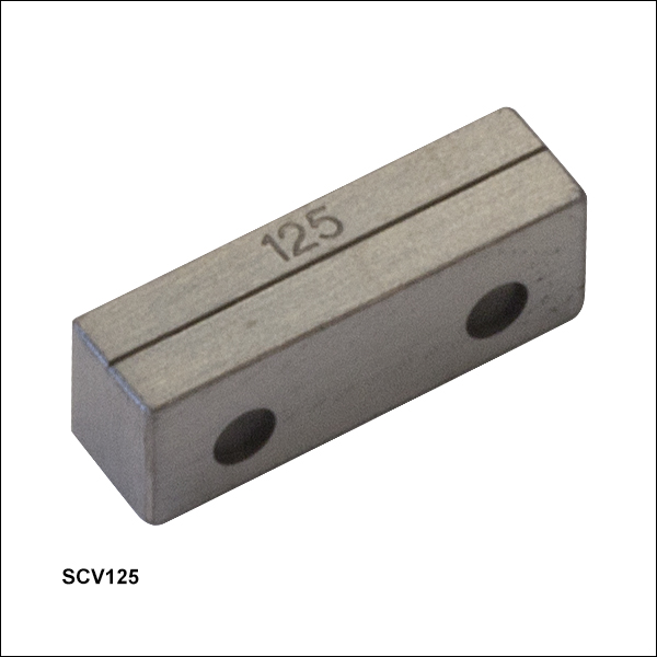
Zoom| Compatible Fiber Cladding Diametersa | |||
|---|---|---|---|
| Item # | Nominal Diameter | Minimum Diameter | Maximum Diameter |
| SCV075 | 75 µm | 68 µm | 82 µm |
| SCV100 | 100 µm | 90 µm | 110 µm |
| SCV125 | 125 µm | 113 µm | 137 µm |
| SCV150 | 150 µm | 135 µm | 165 µm |
| SCV200 | 200 µm | 180 µm | 220 µm |
- V-Groove Inserts Align the Fibers within the Fiber Cleaver Unit
- Five Versions to Support the Workstation's Accepted Cladding Diameters (From 80 µm to 200 µm)
- Two Required: One Each for Left and Right Cleaver
These Bottom Cleaver Inserts secure the fiber inside the cleaving assembly of the workstation. They are sold individually to allow cleaving of differently sized fibers held within the left and right fiber holding blocks. Different inserts are available to support a variety of fiber sizes; compatibility is listed in the table to the right. Please note that the base unit is compatible with fiber cladding from Ø80 µm to 200 µm, even though the inserts can hold fiber cladding diameters outside of this range. Please contact Tech Support for more information.
Two bottom cleaver inserts, one for both the left and right fibers, must be purchased in order to operate your workstation. These can be installed at the factory upon request by contacting Tech Support. If necessary, the cleaver inserts can be replaced by the user. When the cleaving assembly is closed, the top (sold in the next product grouping) and bottom inserts mate to secure the stripped fiber.

 Zoom
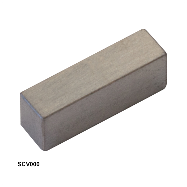
Zoom- Top Insert for the Fiber Cleaver Unit
- Two Required: One Each for Left and Right Cleaver
The SCV000 Top Cleaver Insert is a flat plate that helps secure the fiber inside the cleaving assembly of the workstation. It is sold individually, so two items must be purchased, one for the left and one for the right fiber cleaver.
In addition to these top cleaver inserts, you must buy the bottom insert that matches your fiber size (see the previous product grouping). When purchased with a workstation base unit, the top cleaver inserts can be installed at the factory upon request by contacting Tech Support. If necessary, the cleaver inserts can be replaced by the user. When the cleaving assembly is closed, the top and bottom inserts mate to secure the fiber.

 Zoom
Zoom| Compatible Fiber Cladding Diameters | |||
|---|---|---|---|
| Item # | Nominal Diameter |
Minimum Diameter |
Maximum Diameter |
| VHG125 | 125 µm | 80 µm | 125 µm |
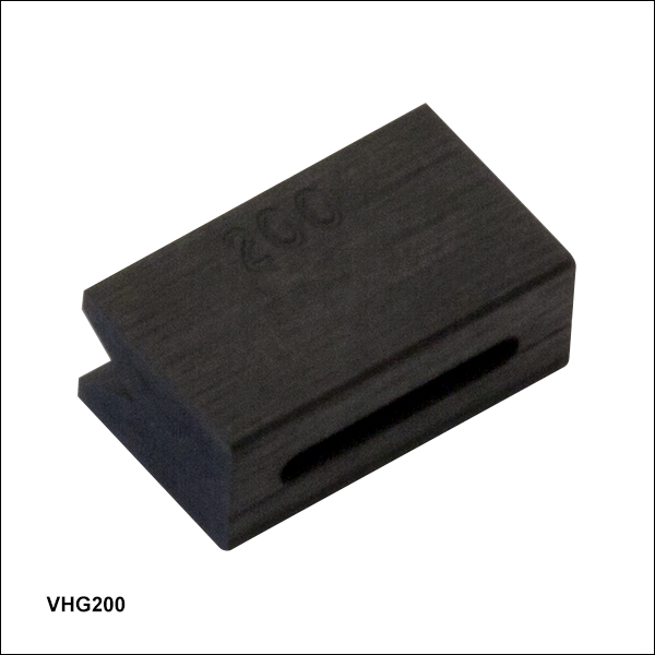
| VHG200 | 200 µm | 150 µm | 200 µm |
- V-Grooves Support Fibers for Fusion Splicing (Two VHG125 are Installed with System)
- Support Cladding Diameters Ranging from 80 µm to 200 µm (See Table to the Right)
- Two Required: One Each for Left and Right Sides of the Splicer Assembly
These Graphite V-Groove Inserts help to position the fiber in the fusion splicer. The fiber size is limited by the size of the channel in the insert; the compatible sizes are listed in the table to the right.
These items are sold individually; two Graphite V-groove inserts, one for the left and one for the right side of the splicer assembly; two VHG125 inserts are included with the system. Due to the alignment precision required, these inserts must be installed and aligned at the factory and are not user replaceable. If you require a different insert size for an existing system, please contact tech support to arrange the reconfiguration.

 Zoom
Zoom| Filament Assembly Specifications | ||
|---|---|---|
| Item # | Filament Material |
Fiber Cladding Diameter (Min / Max) |
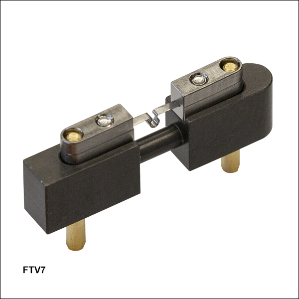
| FTV7 | Tungsten | 80 µm / 200 µm |
| ETV7 | Iridium | 80 µm / 200 µm |
- Two Options Available:
- FTV7 Tungsten Filament Ideal for Most Applications
- ETV7 Iridium Filament Ideal for Soft Glass Fibers
- Omega Shape Provides Uniform Concentric Heat Source
There are two available fusion splicing filaments for the all-in-one workstation. The FTV7 tungsten filament is ideal for most splicing applications, while the ETV7 iridium filament is ideal for soft glass fibers. The omega-shaped filament is housed in an included mount and is easily replaced by the end user. The omega shape provides a uniform concentric heat source for fusing the fiber tips and for an optional post-fusion fire polishing step. Filament lifetimes will depend upon the particular splicing parameters used but are typically about 40 minutes.
One FTV7 filament comes pre-installed in the workstation. Additional filaments may be purchased, but before a new filament can be used in a system, it must be burned in. During the burn-in process, the filament is cycled between its operating temperature and room temperature several times. This stabilizes the thermal properties of the filament so that it produces a more consistent power output and heating performance when current is passed through it. This procedure only needs to be performed once, after which the filament will only need regular normalization. Instructional videos on the burn-in and normalization processes can be viewed in the Tutorial Videos tab above. If splicing performance begins to degrade, filament refurbishments can be ordered by contacting Tech Support.

 Zoom
Zoom| Compatible Coating Diameters | |
|---|---|
| Item # | Recoated Diameter |
| RM280UV | 280 µm |
| RM430UV | 430 µm |
| RM600UV | 600 µm |
- Three Options Available for 280 µm, 430 µm, or 600 µm Recoat Diameter
- Other Sizes up to Ø900 µm Available Upon Request (Contact Tech Support)
- Maximum Recoat Length of 50 mm
- One Mold Assembly Required
There are three available recoater mold assemblies for the all-in-one fiber processing workstation. They are available for 280 µm, 430 µm, or 600 µm coating diameters. Custom mold sizes up to Ø900 µm are available; please contact Tech Support for more information. The assembly is composed of split quartz mold plates, which, when closed, form the cylindrical mold cavity around the exposed section of the fiber being recoated.
During operation, the recoat material (available in the next product grouping) is injected into the mold assembly with a manual injection system that is included in the workstation base unit. Then, UV light cures the recoat material. Cure times are dependent on the mold size, recoat material, and fiber size; they range from approximately 20 - 30 seconds for mold assemblies with well-matched fiber sizes to around 70 seconds for Ø125 - Ø250 µm fibers using the RM600UV mold and the low-index PC373 recoat material. The recoater mold assembly should be cleaned throughly with isopropyl alcohol or acetone between each recoating process; reliable and repeatable performance is highly dependent on the cleanliness of the mold.
One recoater mold assembly must be purchased in order to operate your workstation. The mold can be factory installed prior to shipment upon request by contacting Tech Support. If necessary, the recoat mold assemblies are user replaceable.

 Zoom
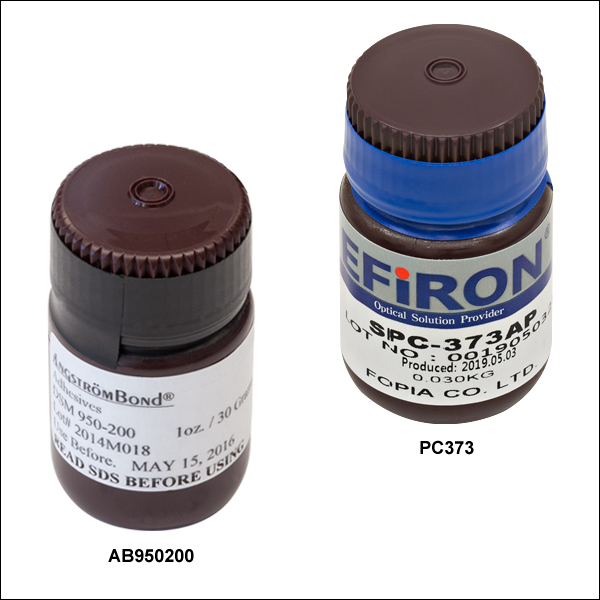
Zoom- AB950200: High-Index Recoat Material
- PC373: Low-Index Recoat Material
Thorlabs offers UV-curable acrylic recoat materials for the fiber processing workstation. We offer both high-index and low-index materials. The recoat material is injected into the recoater mold assembly by a manual injection system included in the workstation base unit. Each bottle includes 1 oz (30 g) of recoat material.
One bottle of recoat material must be purchased in order to operate your workstation.
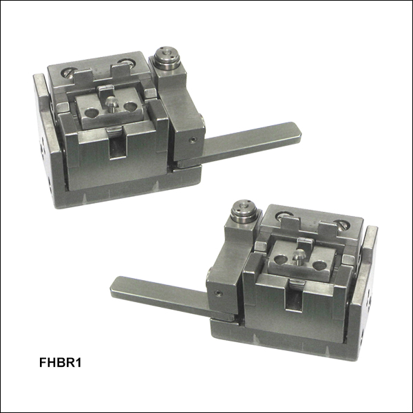
 Fiber Holding Block Set")
 Zoom
ZoomCompatible Systems
- FFS2001PM and FFS2001WS Fiber Preparation, Splicing,
and Proof Testing Workstations
- Replacement Fiber Holding Blocks for Our Fiber Processing Systems (See List to the Right)
- Allows for Rotational Alignment of PM Fiber Prior to Splicing
- Sold as a Set of Two (Left and Right Pair)
- Requires V-Groove Inserts (Available Separately Above)
Fiber Holding Blocks secure the fiber and simplify moving the fibers between the different processing steps. The FFBR1, which is sold as a pair of left and right fiber holding blocks, is the replacement set for the Vytran fiber processing systems listed to the right.
In order to securely hold a fiber with a particular diameter, a set of V-Groove inserts must be installed within the fiber holding block; these can be factory installed prior to shipment upon request by contacting Tech Support. V-Groove inserts must be purchased separately above.

 Zoom
ZoomCompatible Systems
- CAC400 and CAC400A Fiber Cleavers
- LDC401 and LDC401A Fiber Cleavers
- LDC450B Portable Fiber Cleaver
- GPX3800, GPX3850, and GPX3900 Automated Glass Processors with Cleavers
- FFS2001 and FFS2001PT Fiber Preparation and Splicing Workstations
- FFS2001PM and FFS2001WS Fiber Preparation, Splicing,
and Proof Testing Workstations - Former Generation LDC-200 Fiber Cleaver
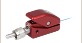
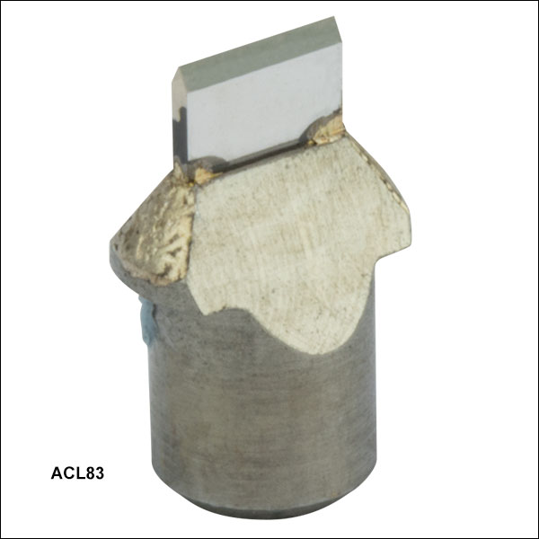
- Replacement Blade for Our Fiber Cleaving Systems (See List to the Right)
- 0.08" (2.0 mm) Long Diamond Blade
- User Installable
Click to Enlarge
The blade is shipped in a protective covering.
The ACL83 Diamond Cleave Blade is a replacement blade for the Vytran fiber processing systems listed to the right. Each system is shipped with a blade included.
When used with proper cleave parameters, a single location on the blade can provide up to 5,000 cleaves (dependent on the cladding properties of the fiber being cleaved). The blade can be positioned approximately 10 times before replacement (assuming proper cleave parameters and usage that does not cause unexpected damage to the blade). Blade replacement instructions for each system are provided in the user manuals.
Note: Severe damage to the blade can occur if conditions cause high stress perpendicular to the edge of the blade or if incorrect parameters are used to cleave the fiber.

 Zoom
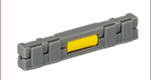
ZoomCompatible Systems
- PTR302 Fiber Rotary Proof Tester
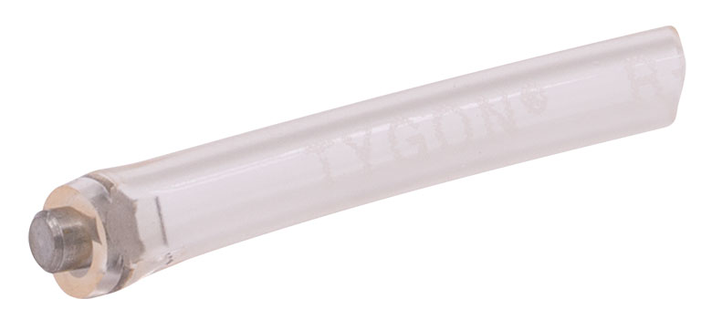
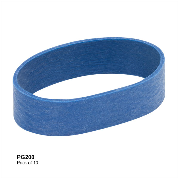
- PTR307(B)* and PTR407(B) Manual Fiber Recoaters with Proof Testers
- FFS2001PT Fiber Preparation and Splicing Workstation
- FFS2001WS Fiber Preparation, Splicing, and Proof Testing Workstation
*These previous-generation items are no longer available for purchase.
The PG200 Proof Test Grips are designed as replacements for the Vytran rotary proof testers listed to the right. Each system is sold with a set of these grips installed.
Proof test grips may need to be replaced when the fiber slips at high tension levels. After the proof test grips are replaced the system will need to be calibrated; please contact Tech Support for details. Instructions for replacing the proof test grips are provided in each system's manual.