 Products Home
Bandpass Filter Kits
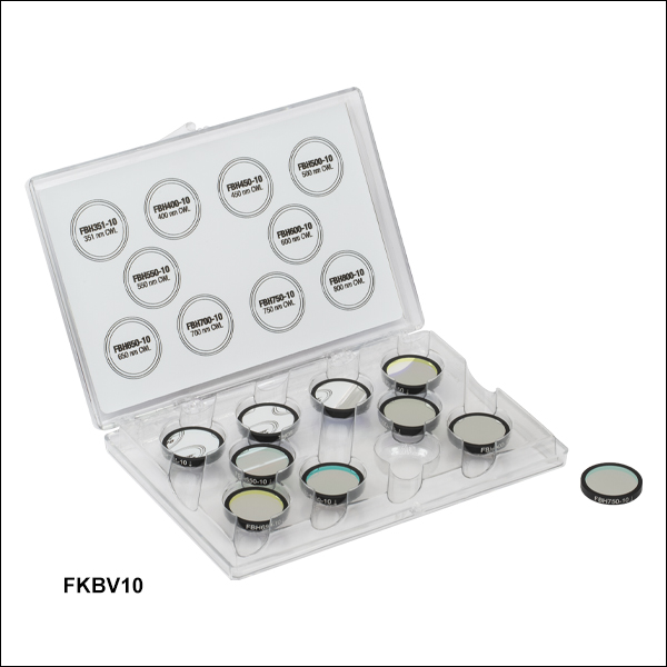
- VIS/NIR Kit, 10 nm Bandpass: 10 Center Wavelengths from 351 to 800 nm
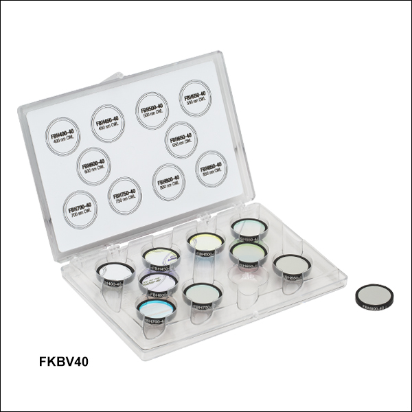
- VIS/NIR Kit, 40 nm Bandpass: 10 Center Wavelengths from 400 to 850 nm
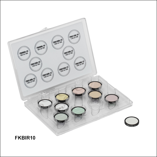
- NIR Kit, 10 - 12 nm Bandpass: 10 Center Wavelengths from 850 to 1600 nm
FKBIR10
NIR Filter Kit
10 - 12 nm FWHM
CWL = 600 nm
FWHM = 40 nm
CWL = 1100 nm
FWHM = 10 nm
CWL = 700 nm
FWHM = 10 nm
FKBV40
VIS/NIR Filter Kit
40 nm FWHM

Please Wait
Click to Enlarge
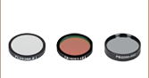
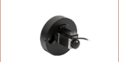
Figure 1.3 Our hard-coated bandpass filter
engraving and transmission is shown here.
Please note that the transmission direction only affects backscatter and reflection, not filter performance.
Features
- Hard-Coated VIS/NIR Bandpass Filter Kits
- Item # FKBV10: 351 to 800 nm Center Wavelengths, 10 nm FWHM
- Item # FKBV40: 400 to 850 nm Center Wavelengths, 40 nm FWHM
- Hard-Coated NIR Bandpass Filter Kit
- Item # FKBIR10: 850 to 1600 nm Center Wavelengths, 10 nm or 12 nm FWHM (Filter Dependent)
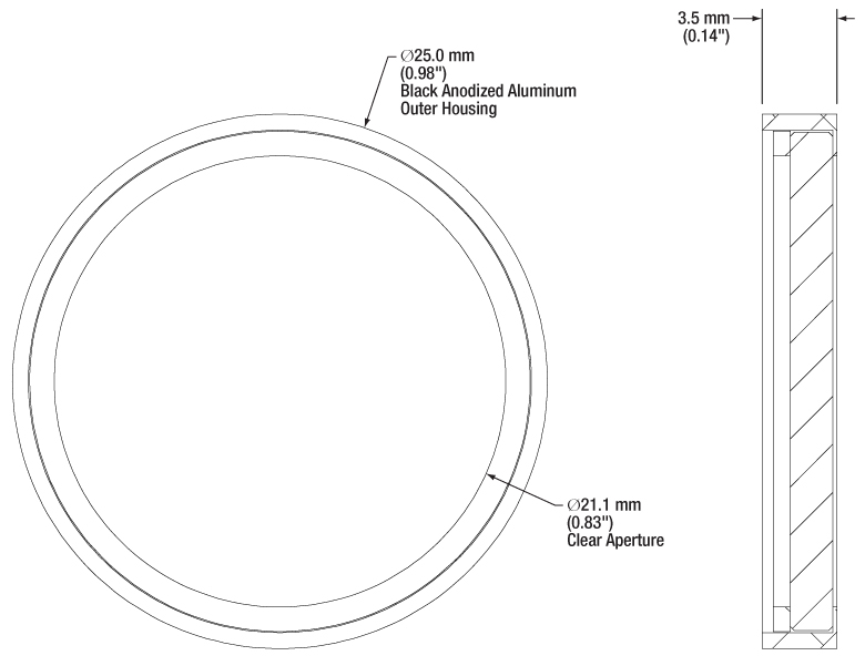
- Engraved Filter Mount with Ø25 mm Ring
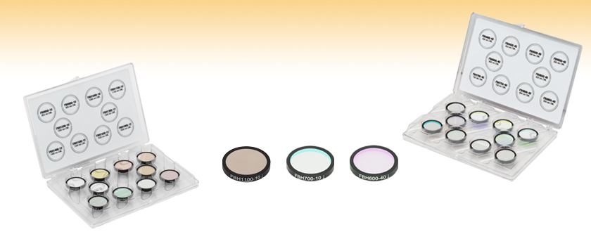
Thorlabs' Bandpass Filter Kits each contain 10 mounted bandpass filters that can be used to transmit a well-defined wavelength band in the VIS/NIR or NIR, while rejecting other unwanted radiation. The bandpass filter kits include a selection of our UV/VIS and NIR Hard-Coated Bandpass Filters.
These bandpass filters feature durable, hard-coated dielectric coatings on a UV fused silica substrate. They provide high transmission, steep cut on and cut off slopes, and excellent suppression in the blocking region. The hard-coated filters are 3.5 mm thick, which allows the Ø25 mm filters to be used as drop-in replacements for our fluorescence emission filters.
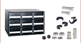
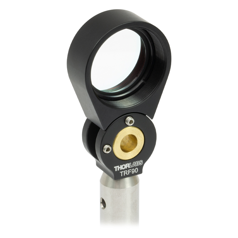
Each filter is mounted in an unthreaded Ø25 mm ring that can be placed into our selection of Ø1" lens tubes and filter mounts using retaining rings, as shown in Figure 1.2. The filter kits come in a convenient plastic box for storage and transportation purposes. Please see the Tutorial tab for more information about the structure and performance of the hard-coated bandpass filters.
Thorlabs also offers a wide range of individually sold bandpass filters. To inquire about our custom bandpass filter options, including the possibility of alternative central wavelengths or bandwidths, please contact Tech Sales. Please note that there is a significant lead time and tooling cost associated with custom filters that makes the purchase of only a few pieces fairly costly.
| Additional Bandpass Filters | ||||
|---|---|---|---|---|
| UV/VIS Hard-Coated Bandpass Filters 300 - 694 nm CWLs |
Wedged Hard-Coated Bandpass Filters 532 - 785 nm CWLs |
NIR Hard-Coated Bandpass Filters 700 - 2000 nm CWLs |
IR Bandpass Filters 1750 - 12 000 nm CWLs |
Bandpass Filter Kits |
| We also offer custom bandpass filters with other central wavelengths or FWHM. To request a quote, contact Tech Sales. | ||||
| General Specifications | |
|---|---|
| Kit Type | Hard-Coated Bandpass Filter Kits (Item #s FKBV10, FKBV40, and FKBIR10) |
| Bandpass Filter Type | Premium Hard-Coated |
| Out of Band Optical Density |
ODavg ≥ 4 (351 nm CWL) ODabs > 5 (CWLs ≥ 400 nm) |
| Clear Aperture | Ø21.1 mm |
| Thickness | 3.5 mm |
| Surface Quality | 60-40 Scratch-Dig |
| Coating | Hard Coated |
| Operating Temperature |
-40 to 90 °Ca |
| Edge Treatment | Mounted in Black Anodized Aluminum Ring |
| Edge Markingsb | Item # |
| Substrate(s) | UV Fused Silicac |
| Damage Threshold | Not Specified |

Click to Enlarge
Figure 3.1 The number of layers shown in this schematic is not indicative of the number of layers in an actual hard-coated bandpass filter. The drawing is also not to scale.
Hard-Coated Bandpass Filter Structure
A bandpass filter is created by depositing layers of material on the surface of the substrate. For our hard-coated bandpass filters, the coating is comprised of dielectric stacks alternating with dielectric spacer layers. Each dielectric stack is composed of a large number of alternating layers of low-index and high-index material. The thickness of each layer in the dielectric stack is λ/4, where λ is the design center wavelength of the bandpass filter (i.e. the wavelength designed to have highest transmittance through the filter at normal incidence). The spacer layers are placed in between the stacks and have a thickness of (nλ)/2, where n is an integer. A Fabry-Perot cavity is formed by each spacer layer sandwiched between dielectric stacks. The filter is mounted in an engraved metal ring for protection and ease of handling.
Filter Operation Overview
The constructive interference conditions of a Fabry-Perot cavity allow light at the center wavelength, and a small band of wavelengths to either side, to be transmitted efficiently, while destructive interference prevents the light outside the passband from being transmitted. However, the band of blocked wavelengths on either side of the center wavelength is small. To increase the blocking range of the filter, materials with broad blocking ranges are used as the substrate or to coat the spacer layers. Although these materials effectively block out-of-band transmission of incident radiation, they also decrease the transmission through the filter in the passband.
Filter Temperature
Click to Enlarge
Figure 3.2 This plot displays the forward (solid lines) and backward (dashed lines) transmission through the FBH800-10 and FBH800-40 hard-coated bandpass filters.
The center wavelength of the filter can be tuned slightly (~1 nm over the operating range of the filter) by changing the temperature of the filter. This is primarily due to the slight thermal expansion or contraction of the layers.
Filter Orientation
Direction of Transmission
An engraved arrow on the edge of the filter is used to indicate the recommended direction for the transmission of light through the filter. Orienting the coated side toward the source will reduce unwanted scattering and minimize reflections sent back toward the source. Using the filter in the opposite orientation will not, however, significantly affect the performance of the filter. Figure 3.2 was made by illuminating the filter with a low intensity broadband light and measuring the transmission as a function of wavelength. This plot shows that the direction of transmission through the filter has very little effect on the intensity and the spectrum of the light transmitted through the filter. The minimal variation between the forward and backward traces is most likely due to a small shift in the incident angle of the light on the filter introduced when the filter was removed, flipped over, and replaced in the jig.
Angle of Incidence (AOI)
The filter is intended to be used with collimated light normally incident on the surface of the filter. For uncollimated light or light striking the surface at an angle not normally incident to the surface, the center wavelength (wavelength corresponding to peak transmission) will shift toward lower wavelengths and the shape of the transmission region (passband) will change. Varying the angle of incidence (AOI) by a small amount can be used to effectively tune the passband over a narrow range. Large changes in the incident angle will cause larger shifts in the center wavelength but will also significantly distort the shape of the passband and, more importantly, cause a significant decrease in the transmittance of the passband. Figures 3.3, 3.4, 3.5, and 3.6 show examples of the change of the passband, transmission, and center wavelength (CWL) with when the AOI is changed for various filters. Filters with passband full width half maxima (FWHM) in the range of 1 nm to 5 nm are particularly susceptible to these shifts and extra care should be taken to ensure they are set to the desired AOI. Figures 3.3, 3.4, 3.5, and 3.6 are given in order of increasing nominal passband FWHM.
Click to Enlarge
Figure 3.4 This plot displays the changing transmission and FWHM of the passband for an FLH1064-3 hard-coated bandpass filter at varying angles of incidence (AOI). The design CWL and passband of the FLH1064-3 filter are 1064 nm and 3 nm, respectively.
Click to Enlarge
Figure 3.3 This plot displays the changing transmission and FWHM of the passband for an FLH532-1 hard-coated bandpass filter at varying angles of incidence (AOI). The design CWL and passband of the FLH532-1 filter are 532 nm and 1 nm, respectively.
Click to Enlarge
Figure 3.6 This plot displays the changing transmission and FWHM of the passband for an FLH1030-10 hard-coated bandpass filter at varying angles of incidence (AOI). The design CWL and passband of the FLH1030-10 filter are 1030 nm and 10 nm, respectively.
Click to Enlarge
Figure 3.5 This plot displays the changing transmission and FWHM of the passband for an FBH800-10 hard-coated bandpass filter at varying angles of incidence (AOI). The design CWL and passband of the FBH800-10 filter are 800 nm and 10 nm, respectively.
Figures 3.7, 3.8, 3.9, 3.10, and 3.11 show how the properties of the FLH532-1, FLH1064-3, and FLH1030-10 hard-coated bandpass filters change as the AOI is varied.

Click to Enlarge
Figure 3.8 This plot shows the the FWHM at the CWL corresponding to the peak transmission at the given AOI. Item #'s FLH532-1, FLH1064-3, and FLH1030-10 have design center wavelengths of 532, 1064, and 1030 nm with 1, 3, and 10 nm FWHM passbands, respectively.

Click to Enlarge
Figure 3.7 This plot displays the transmission at the design center wavelength as the angle of incidence is varied. As can be seen in this graph, the transmission of filters with wider passbands are less sensitive to changes in the AOI. Item #'s FLH532-1, FLH1064-3, and FLH1030-10 have design center wavelengths of 532, 1064, and 1030 nm with 1, 3, and 10 nm FWHM passbands, respectively.

Click to Enlarge
Figure 3.11 This plot displays the center wavelength that provides the maximum transmission for a given angle of incidence for an FLH1030-10 hard-coated bandpass filter with a design CWL of 1030 nm and a passband FWHM of 10 nm.
Click to Enlarge
Figure 3.10 This plot displays the center wavelength that provides the maximum transmission for a given angle of incidence for an FLH1064-3 hard-coated bandpass filter with a design CWL of 1064 nm and a passband FWHM of 3 nm.

Click to Enlarge
Figure 3.9 This plot displays the center wavelength and peak transmission at that wavelength for a given angle of incidence for an FLH532-1 hard-coated bandpass filter with design CWL of 532 nm and passband FWHM of 1 nm.
Filter Reflectance
Thorlabs' hard-coated bandpass filters reflect out-of-band light with high efficiency. Figure 3.12 shows the measured reflectance of an FBH1200-10 hard-coated bandpass filter with a design CWL of 1200 nm and passband FWHM of 10 nm. The blocking region for this filter is specified as ODabs > 5 between the ranges of 200 - 1180 nm and 1220 - 1700 nm.
Click to Enlarge
Figure 3.12 This plot displays the reflectance of an FBH1200-10 hard-coated bandpass filter over an extended range from 200 nm to 1800 nm. As can be seen in the graph, the filter reflectance is high within the blocking region of 200 - 1180 nm and 1220 - 1700 nm. The drop in reflectance below 300 nm is due to increased absorption by the glass substrate.
Out-of-Band Filter Performance
The transmission and optical density properties of the hard-coated bandpass filters will vary for far out-of-band wavelengths. Figures 3.13 and 3.14 show the variation in transmission and optical density for wavelengths far outside the specified blocking regions of 200 - 379 nm and 401 - 1200 nm for an FBH390-10 hard-coated bandpass filter. The FBH390-10 has a design CWL of 390 nm and a passband FWHM of 10 nm. The blocking region is specified to be ODabs > 5 between the ranges of 200 - 379 nm and 401 - 1200 nm.
Click to Enlarge
Figure 3.14 This plot displays the optical density (OD) measured between 200 nm and 1600 nm for the FBH390-10 hard-coated bandpass filter. The OD drops off for wavelengths beyond 1200 nm.
Click to Enlarge
Figure 3.13 This plot displays the transmission through an FBH390-10 hard-coated bandpass filter over an extended range from 200 nm to 1600 nm. The transmission varies for wavelengths beyond 1200 nm.
| Posted Comments: | |
tebeech
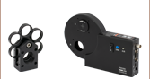
(posted 2014-03-05 04:53:36.227) Despite the fact that a filter wheel is displayed as a "related item" along the sidebar, the mounted bandpass filters are too thick to be mounted in such a device. Specifically, we purchased the visible bandpass filter kit FKB-VIS-10 and attempted to mount the filters in a FW1A. The thickness of the filters exceeds the thickness of the filter wheel mount and as such there is no way of affixing the filters in place. It is remarkable to me that a thorlabs filter cannot be mounted in a thorlabs filter wheel. Such basic must have been tested and as yet I am forced to purchase additional items to achieve basic functionality. jlow
(posted 2014-03-05 10:48:15.0) Response from Jeremy at Thorlabs: I apologize for this mistake on our website. We have removed the thin filter wheels from the related items. To mount the filters to FW1A, you would need to get SM1L05. I will contact you directly about this. |

 Zoom
Zoom| Item #a | Center Wavelength (Transmissionb) |
FWHM | Blocking Regions (Optical Density) | Transmission Datac |
|---|---|---|---|---|
| FBH351-10 | 351 nm (T ≥ 85%) | 10 nm | 200 - 388.10 nm, 364.14 - 1200 nm (ODavg ≥ 4) | |
| FBH400-10 | 400 nm (T > 90%) | 10 nm | 200 - 389 nm, 411 - 1200 nm (ODabs > 5) | |
| FBH450-10 | 450 nm (T > 90%) | 10 nm | 200 - 430 nm, 470 - 1200 nm (ODabs > 5) | |
| FBH500-10 | 500 nm (T > 90%) | 10 nm | 200 - 487 nm, 512 - 1200 nm (ODabs > 5) | |
| FBH550-10 | 550 nm (T > 90%) | 10 nm | 200 - 536 nm, 564 - 1200 nm (ODabs > 5) | |
| FBH600-10 | 600 nm (T > 90%) | 10 nm | 200 - 586 nm, 614 - 1200 nm (ODabs > 5) | |
| FBH650-10 | 650 nm (T > 90%) | 10 nm | 200 - 630 nm, 670 - 1200 nm (ODabs > 5) | |
| FBH700-10 | 700 nm (T > 90%) | 10 nm | 200 - 684 nm, 716 - 1200 nm (ODabs > 5) | |
| FBH750-10 | 750 nm (T > 90%) | 10 nm | 200 - 733 nm, 766 - 1200 nm (ODabs > 5) | |
| FBH800-10 | 800 nm (T > 90%) | 10 nm | 200 - 771 nm, 829 - 1200 nm (ODabs > 5) |
- All specifications are valid for 0° AOI.
- Transmission at Center Wavelength
- Click on
 for a plot and downloadable data. Please note that transmission is only guaranteed for the specified center wavelength and that the data in the plots is typical. Performance may vary from lot to lot.

 Zoom
Zoom| Item #a | Center Wavelength (Transmissionb) |
FWHM | Blocking Regions (Optical Density) | Transmission Datac |
|---|---|---|---|---|
| FBH400-40 | 400 nm (T > 90%) | 40 nm | 200 - 368 nm, 433 - 1200 nm (ODabs > 5) | |
| FBH450-40 | 450 nm (T > 90%) | 40 nm | 200 - 423 nm, 477 - 1200 nm (ODabs > 5) | |
| FBH500-40 | 500 nm (T > 90%) | 40 nm | 200 - 472 nm, 527 - 1200 nm (ODabs > 5) | |
| FBH550-40 | 550 nm (T > 90%) | 40 nm | 200 - 521 nm, 578 - 1200 nm (ODabs > 5) | |
| FBH600-40 | 600 nm (T > 90%) | 40 nm | 200 - 571 nm, 629 - 1200 nm (ODabs > 5) | |
| FBH650-40 | 650 nm (T > 90%) | 40 nm | 200 - 611 nm, 690 - 1200 nm (ODabs > 5) | |
| FBH700-40 | 700 nm (T > 90%) | 40 nm | 200 - 669 nm, 730 - 1200 nm (ODabs > 5) | |
| FBH750-40 | 750 nm (T > 90%) | 40 nm | 200 - 718 nm, 781 - 1200 nm (ODabs > 5) | |
| FBH800-40 | 800 nm (T > 90%) | 40 nm | 200 - 757 nm, 845 - 1200 nm (ODabs > 5) | |
| FBH850-40 | 850 nm (T > 90%) | 40 nm | 200 - 805 nm, 896 - 1200 nm (ODabs > 5) |
- All specifications are valid for 0° AOI.
- Transmission at Center Wavelength
- Click on for a plot and downloadable data. Please note that transmission is only guaranteed for the specified center wavelength and that the data in the plots is typical. Performance may vary from lot to lot.

 Zoom
Zoom| Item #a | Center Wavelength (Transmissionb) |
FWHM | Blocking Regions (Optical Density) | Transmission Datac |
|---|---|---|---|---|
| FBH850-10 | 850 (T > 90%) | 10 nm | 200 - 830 nm, 870 - 1200 nm (ODabs > 5) | |
| FBH900-10 | 900 (T > 90%) | 10 nm | 200 - 881 nm, 918 - 1200 nm (ODabs > 5) | |
| FBH1000-10 | 1000 (T > 90%) | 10 nm | 200 - 980 nm, 1020 - 1200 nm (ODabs > 5) | |
| FBH1100-10 | 1100 (T > 90%) | 10 nm | 200 - 1064 nm, 1138 - 1800 nm (ODabs > 5) | |
| FBH1200-10 | 1200 (T > 90%) | 10 nm | 200 - 1180 nm, 1220 - 1700 nm (ODabs > 5) | |
| FBH1300-12 | 1300 (T > 90%) | 12 nm | 200 - 1255 nm, 1345 - 1800 nm (ODabs > 5) | |
| FBH1400-12 | 1400 (T > 90%) | 12 nm | 200 - 1352 nm, 1450 - 1800 nm (ODabs > 5) | |
| FBH1500-12 | 1500 (T > 90%) | 12 nm | 200 - 1449 nm, 1551 - 1800 nm (ODabs > 5) | |
| FBH1550-12 | 1550 (T > 90%) | 12 nm | 200 - 1530 nm, 1570 - 1700 nm (ODabs > 5) | |
| FBH1600-12 | 1600 (T > 90%) | 12 nm | 200 - 1550 nm, 1652 - 1800 nm (ODabs > 5) |
- All specifications are valid for AOI = 0°.
- Transmission at Center Wavelength
- Click on for a plot and downloadable data. Please note that transmission is only guaranteed for the specified center wavelength and that the data in the plots is typical. Performance may vary from lot to lot.