 Products Home
IR Fiber Optic Isolators with PM Fiber (1290 - 2010 nm)

- Center Wavelengths at 1310, 1550, or 2000 nm
- Minimum Isolation from 28 dB to 45 dB
- FC/APC Terminated or Unterminated PM Fiber
- OEM and Build-to-Order Fiber Isolators Available
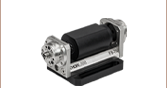
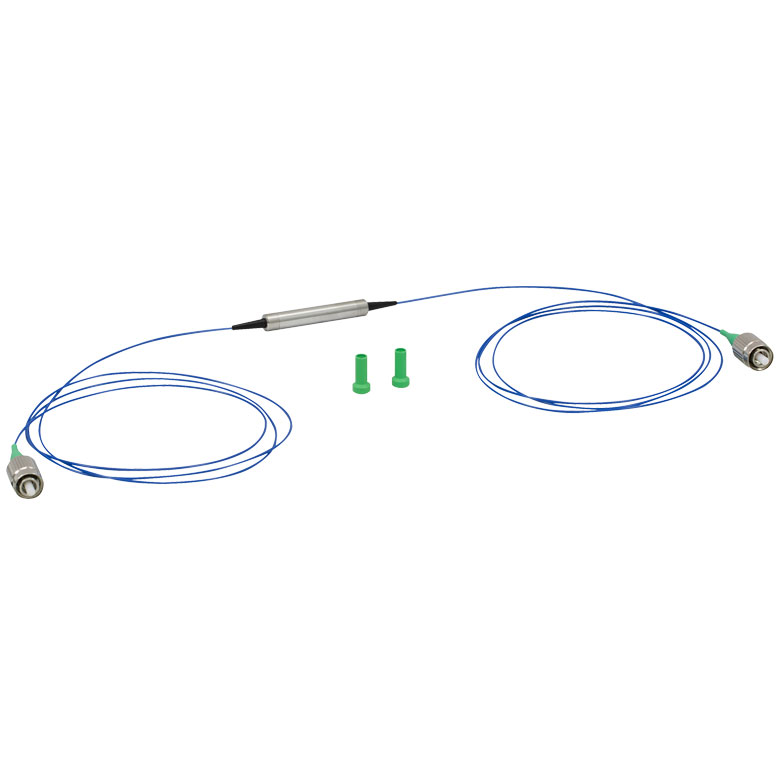
IO-G-1550-APC
1550 nm, FC/APC Connectors
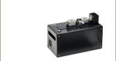
IO-J-2000
2000 nm, No Connectors
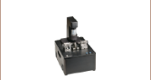
IO-L-2000
2000 nm, 10 W Max Power, No Connectors
FC/APC


Please Wait
| Selection Guide for Isolators (Click Here for Our Full Selection) |
||
|---|---|---|
| Fiber Isolators | ||
| Spectral Region | Wavelength Range | Fiber Type |
| Visible | 650 - 670 nm | SM |
| NIR | 770 - 1060 nm | SM |
| PM | ||
| Nd:YAG | 1064 nm | SM |
| PM | ||
| IR | 1290 - 2010 nm | SM |
| PM | ||
| Fiber Isolators for Broadband SLDsa | ||
| Free-Space Isolators | ||
| Custom Isolators | ||
Custom Isolators
- Customizable Wavelength, Aperture, Max Power, Housing, Polarizers, and Operating Temperature
- Pricing Similar to Stock Units
- Wide Range of OEM Capabilities
- Please Contact Tech Support or See Our Custom Isolators Page
Features
- Minimize Feedback into Optical Systems
- Operating Wavelength Ranges of 1290 - 1330 nm, 1530 - 1570 nm, 1540 - 1560 nm, or 1990 - 2010 nm
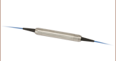
- 0.8 m to 1 m of PANDA PM Fiber on Both Sides
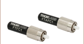
- Available with 2.0 mm Narrow Key FC/APC Connectors or Unterminated
- Designed for CW Applications
- Each Unit is Individually Tested
- Custom Isolators Available (See the Custom Isolators Tab)
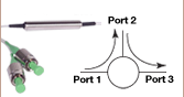
Fiber isolators protect light sources from back reflections and signals that can cause intensity noise and optical damage. Optical isolators, also known as Faraday isolators, are magneto-optic devices that preferentially transmit light in the forward direction while absorbing or displacing light propagating in the reverse direction (see the schematic below). Please see the Isolator Tutorial tab for an explanation of the operating principles of a Faraday isolator.

Click to Enlarge
This schematic shows a single-stage, polarization-dependent isolator. Light propagating in the reverse direction is rejected by the input polarizer. For more detailed information and a comparison to dual-stage isolators, please see the Isolator Tutorial tab.
The IOT-G-1550A dual-stage isolator includes an additional Faraday rotator and polarizer compared to a single-stage isolator in order to achieve greater isolation. This isolator type is recommended for use with ultra-low-noise lasers, which are sensitive to optical feedback.
Thorlabs offers polarization-dependent IR isolators with polarization-maintaining (PM) fiber below. The schematic to the left illustrates the polarization dependence of these isolators. In contrast, our single-mode (SM) fiber polarization-independent IR isolators are designed to connect to SM fiber.
Our high-power units are built using a specialized fiber end face process that increases the maximum power. There is 0.8 m to 1 m of fiber built into each side of the isolator, and an arrow on the body indicates the transmission direction. In addition, each unit is tested before shipment to ensure compliance with our specifications and a complete test report comes with every serialized part.
Thorlabs also manufactures free-space isolators and fiber isolators designed for the infrared range. Please use the Selection Guide table above for more information. If you do not see an isolator that suits your application, please refer to the Custom Isolators tab for information on our build-to-order options, or contact Tech Support.
Optical Isolator Tutorial
Function
An optical isolator is a passive magneto-optic device that only allows light to travel in one direction. Isolators are used to protect a source from back reflections or signals that may occur after the isolator. Back reflections can damage a laser source or cause it to mode hop, amplitude modulate, or frequency shift. In high-power applications, back reflections can cause instabilities and power spikes.
An isolator's function is based on the Faraday Effect. In 1842, Michael Faraday discovered that the plane of polarized light rotates while transmitting through glass (or other materials) that is exposed to a magnetic field. The direction of rotation is dependent on the direction of the magnetic field and not on the direction of light propagation; thus, the rotation is non-reciprocal. The amount of rotation β equals V x B x d, where V, B, and d are as defined below.
Click to Enlarge
Figure 54A Faraday Rotator's Effect on Linearly Polarized Light
Faraday Rotation
β = V x B x d
V: the Verdet Constant, a property of the optical material, in radians/T • m.
B: the magnetic flux density in teslas.
d: the path length through the optical material in meters.
An optical isolator consists of an input polarizer, a Faraday rotator with magnet, and an output polarizer. The input polarizer works as a filter to allow only linearly polarized light into the Faraday rotator. The Faraday element rotates the input light's polarization by 45°, after which it exits through another linear polarizer. The output light is now rotated by 45° with respect to the input signal. In the reverse direction, the Faraday rotator continues to rotate the light's polarization in the same direction that it did in the forward direction so that the polarization of the light is now rotated 90° with respect to the input signal. This light's polarization is now perpendicular to the transmission axis of the input polarizer, and as a result, the energy is either reflected or absorbed depending on the type of polarizer.
Click to Enlarge
Figure 54B A single-stage, polarization-dependent isolator. Light propagating in the reverse direction is rejected by the input polarizer.
Polarization-Dependent Isolators
The Forward Mode
In this example, we will assume that the input polarizer's axis is vertical (0° in Figure 54B). Laser light, either polarized or unpolarized, enters the input polarizer and becomes vertically polarized. The Faraday rotator will rotate the plane of polarization (POP) by 45° in the positive direction. Finally, the light exits through the output polarizer which has its axis at 45°. Therefore, the light leaves the isolator with a POP of 45°.
In a dual-stage isolator, the light exiting the output polarizer is sent through a second Faraday rotator followed by an additional polarizer in order to achieve greater isolation than a single-stage isolator.
The Reverse Mode
Light traveling backwards through the isolator will first enter the output polarizer, which polarizes the light at 45° with respect to the input polarizer. It then passes through the Faraday rotator rod, and the POP is rotated another 45° in the positive direction. This results in a net rotation of 90° with respect to the input polarizer, and thus, the POP is now perpendicular to the transmission axis of the input polarizer. Hence, the light will either be reflected or absorbed.
 Click for Details
Figure 54C A single-stage, polarization-independent isolator. Light is deflected away from the input path and stopped by the housing.
Polarization-Independent Fiber Isolators
The Forward Mode
In a polarization independent fiber isolator, the incoming light is split into two branches by a birefringent crystal (see Figure 54C). A Faraday rotator and a half-wave plate rotate the polarization of each branch before they encounter a second birefringent crystal aligned to recombine the two beams.
In a dual-stage isolator, the light then travels through an additional Faraday rotator, half-wave plate, and birefringent beam displacer before reaching the output collimating lens. This achieves greater isolation than the single-stage design.
The Reverse Mode
Back-reflected light will encounter the second birefringent crystal and be split into two beams with their polarizations aligned with the forward mode light. The faraday rotator is a non-reciprocal rotator, so it will cancel out the rotation introduced by the half wave plate for the reverse mode light. When the light encounters the input birefringent beam displacer, it will be deflected away from the collimating lens and into the walls of the isolator housing, preventing the reverse mode from entering the input fiber.
General Information
Damage Threshold
With 25 years of experience and 5 U.S. patents, our isolators typically have higher transmission and isolation than other isolators, and are smaller than other units of equivalent aperture. For visible to YAG laser Isolators, Thorlabs' Faraday Rotator crystal of choice is TGG (terbium-gallium-garnet), which is unsurpassed in terms of optical quality, Verdet constant, and resistance to high laser power. Thorlabs' TGG Isolator rods have been damage tested to 22.5 J/cm2 at 1064 nm in 15 ns pulses (1.5 GW/cm2), and to 20 kW/cm2 CW. However, Thorlabs does not bear responsibility for laser power damage that is attributed to hot spots in the beam.
Magnet
The magnet is a major factor in determining the size and performance of an isolator. The ultimate size of the magnet is not simply determined by magnetic field strength but is also influenced by the mechanical design. Many Thorlabs magnets are not simple one piece magnets but are complex assemblies. Thorlabs' modeling systems allow optimization of the many parameters that affect size, optical path length, total rotation, and field uniformity. Thorlabs' US Patent 4,856,878 describes one such design that is used in several of the larger aperture isolators for YAG lasers. Thorlabs emphasizes that a powerful magnetic field exists around these Isolators, and thus, steel or magnetic objects should not be brought closer than 5 cm.
Temperature
The magnets and the Faraday rotator materials both exhibit a temperature dependence. Both the magnetic field strength and the Verdet Constant decrease with increased temperature. For operation greater than ±10 °C beyond room temperature, please contact Technical Support.
Pulse Dispersion
Pulse broadening occurs anytime a pulse propagates through a material with an index of refraction greater than 1. This dispersion increases inversely with the pulse width and therefore can become significant in ultrafast lasers.
τ: Pulse Width Before Isolator
τ(z): Pulse Width After Isolator
Example:
τ = 197 fs results in τ(z) = 306 fs (pictured in Figure 54D)
τ = 120 fs results in τ(z) = 186 fs
Click to Enlarge
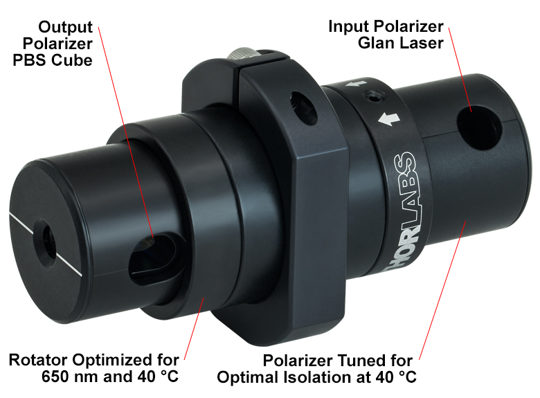
Figure 32A Custom Isolator Example
Custom Adjustable Narrowband Isolator with Different Input and Output Polarizers Optimized for 650 nm Wavelength and 40 °C Temperature.
OEM Application Services
- Direct Integration to Laser Head Assemblies
- Combination Isolator and Fiber Coupling Units
- Minimum Footprint Packages
- Filter Integration
- Active Temperature Control and Monitoring
- Feedback Monitoring
- Environmental Qualification
- Private Labeling
- ITAR-Compliant Assembly
OEM and Non-Standard Isolators
In an effort to provide the best possible service to our customers, Thorlabs has made a commitment to ship our most popular free-space and fiber isolator models from stock. We currently offer same-day shipping on more than 90 isolator models. In addition to these stock models, non-stock isolators with differing aperture sizes, wavelength ranges, package sizes, and polarizers are available. In addition, we can create isolators tuned for specific operating temperatures and isolators that incorporate thermistors with heating or cooling elements for active temperature control and monitoring. These generally have the same price as a similar stock unit. If you would like a quote on a non-stock isolator, please fill out the form below and a member of our staff will be in contact with you.
Thorlabs has many years of experience working with OEM, government, and research customers, allowing us to tailor your isolator to specific design requirements. In addition to customizing our isolators (see the OEM Application Services list), we also offer various application services.
| Table 32B Specifications | |
|---|---|
| Parameter | Range |
| Wavelength Range | From 365 - 4550 nma |
| Aperture Sizes | Up to Ø15 mm |
| Polarization Dependence | Dependent or Independent |
| Max Powerb | Up to 2 GW/cm² |
| Isolation | Up to 60 dB (Tandem Units) |
| Operating Temperature | 10 - 70 °C |
Free-Space Isolators
We are able to provide a wide range of flexibility in manufacturing non-stock, free-space isolators. Almost any selection of specifications from our standard product line can be combined to suit a particular need. Table 32B shows the range of specifications that we can meet.
We offer isolators suitable for both narrowband and broadband applications. The size of the housing is very dependent on the desired maximum power and aperture size, so please include a note in the quote form below if you have special requirements.
Faraday Rotators
We offer Faraday rotators center wavelengths from 532 nm to 1550 nm. These are the same components used to make our isolators and rotate the polarization of incoming light by 45°. Please contact Tech Support if you require a Faraday rotator with a rotation angle or center wavelength outside of the aforementioned specifications.
| Table 32C Specifications | |
|---|---|
| Parameter | Range |
| Wavelength Range | From 633 - 2050 nma |
| Polarization Dependence | Dependent or Independent |
| Max Powerb (Fiber to Free-Space) | 30 W |
| Max Powerb (Fiber to Fiber) | 20 W |
| Operating Temperature | 10 - 70 °C |
Fiber Isolators
Thorlabs is uniquely positioned to draw on experience in classical optics, fiber coupling, and isolators to provide flexible designs for a wide range of fiber optic specifications. Current design efforts are focused on increasing the Maximum power of our fiber isolators at and near the 1064 nm wavelength. We offer models with integrated ASE filters and taps. Table 32C highlights the range of specifications that we can meet.
The fiber used is often the limiting factor in determining the Maximum power the isolator can handle. We have experience working with single mode (SM) and polarization-maintaining fibers (PM); single-, double- and triple-clad fibers; and specialty fibers like 10-to-30 µm LMA fibers and PM LMA fibers. For more information about the fiber options available with our custom isolators, please see Tables 32D and 32E.
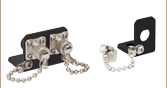
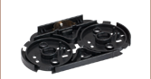
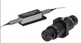
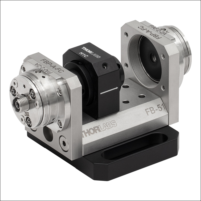
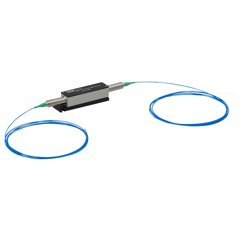
In the spectral region below 633 nm, we recommend mounting one of our free-space isolators in a FiberBench system. A FiberBench system consists of pre-designed modules that make it easy to use free-space optical elements with a fiber optic system while maintaining excellent coupling efficiency. Upon request, we can provide select stock isolators in an optic mount with twin steel dowel pins for our FiberBench systems, as shown to the left.
We are also in the process of extending our fiber isolator capabilities down into the visible region. For more information, please contact Technical Support.
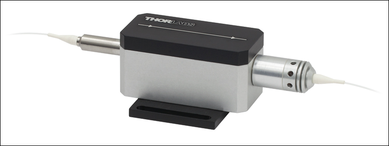
Custom Fiber Isolator
Custom Free-Space Isolator for Wavelengths Below 633 nm
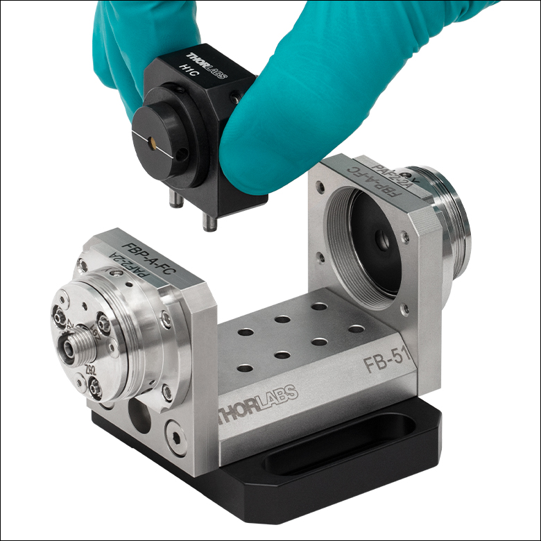
Click to Enlarge
Twin Steel Pins Insert into FiberBench
Click to Enlarge
Mounted Isolator
| Table 32D Polarization Independent Fiber |
|---|
| Table 32E Polarization Maintaining Fiber |
|---|
Make to Order Options
Tables 32F, 32G, 32H, and 32J provide information on some common isolator and rotator specials we have manufactured in the past. We keep the majority of the components for these custom isolators in stock to ensure quick builds, so these specials are available with an average lead time of only 2-4 weeks. Please use the Non-Stock Isolator Worksheet below for a quote.
| Table 32F Adjustable Narrowband Isolators |
|---|
| Table 32G Faraday Rotators |
|---|
| Table 32H Fixed Narrowband Isolators |
|---|
| Table 32J Fixed Broadband Isolators |
|---|
Custom Request Form
Request a custom isolator quote using the form below or by contacting us for more information at (973) 300-3000.
| Posted Comments: | |
philipp.kucirek
(posted 2014-05-09 11:55:44.847) Hello,
can you also offer isolators for 2400nm ? I am intgerested in a PM fiber coupled isolator for a few mW of power. I understand that the fiber is quite a problem at this wavelength so it would be accepable to use PM2000 fiber.
Thanks and best regards,
Philipp Kucirek pbui
(posted 2014-05-21 03:50:06.0) Thank you for your interest. Though we are currently unable to offer this custom isolator, we will keep your request in mind when expanding our catalog. |
The following selection guide contains all of Thorlabs' Fiber Optical Isolators. Click the colored bars below to to see specifications and options for each wavelength range and isolator type. Please note that Thorlabs also offers free space optical isolators and custom optical isolators.
IO-G-1310(-APC) Simplified Mechanical Drawing
| Click Image to Enlarge | 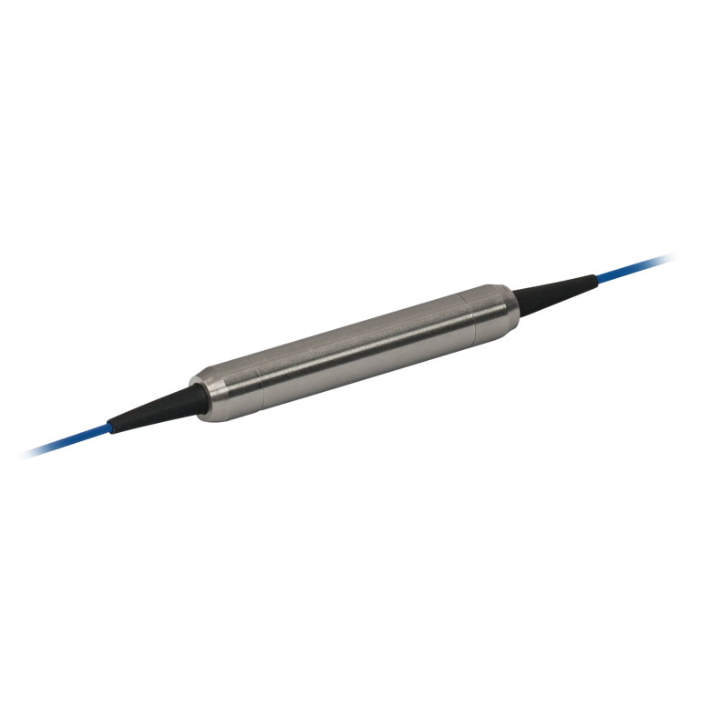 |
| Item #a | IO-G-1310 IO-G-1310-APCb |
| Fiber Type | PM |
| Polarization Dependence | Independent |
| Isolator Design | Single Stage |
| Center Wavelength | 1310 nm |
| Operating Range | 1290 - 1330 nm |
| Max Powerc,d (Without Connectors) |
≤300 mW (CW)e |
| Isolationf | 28 dB (Min) |
| Performance Graph (Click for Plot) |
 |
| Insertion Loss (Without Connectors) | 0.55 dBg (Max) |
| Polarization Extinction Ratio (PER) | ≥20 dBg |
| Return Loss | ≥55 dBg |
| Fiber | Fujikura SM13-PS-U25A |
| Click Image to Enlarge | 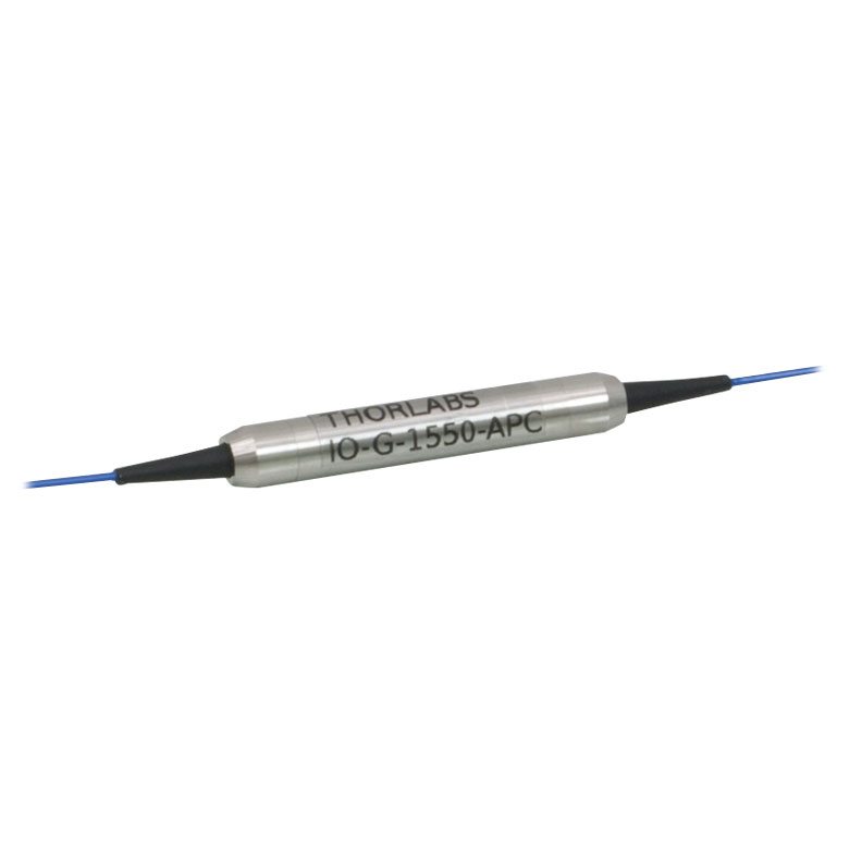 |
 |
 |
| Item #a | IO-G-1550 IO-G-1550-APCb |
IOT-G-1550Ab | IO-J-1550 IO-J-1550APCb |
| Fiber Type | PM | PM | PM |
| Polarization Dependence | Independent | Fast Axis Blocked | Fast Axis Blocked |
| Isolator Design | Single Stage | Dual Stage | Single Stage |
| Center Wavelength | 1550 nm | 1550 nm | 1550 nm |
| Operating Range | 1530 - 1570 nm | 1530 - 1570 nm | 1540 - 1560 nm |
| Max Powerc,d (Without Connectors) |
≤300 mW (CW)e | ≤300 mW (CW)e | 5 W (CW)e |
| Isolationf | 28 dB (Min) | 45 dB (Min) 55 dB (Typ.) |
35 dB (Min) 38 dB (Typ.) |
| Performance Graph (Click for Plot) |
 |
 |
 |
| Insertion Loss (Without Connectors) | 0.55 dBg (Max) | ≤0.85 dB | 0.7 dB (Typ.) 0.9 dB (Max) |
| Polarization Extinction Ratio (PER) | ≥20 dBg | ≥20 dB | ≥20 dB |
| Return Loss | ≥55 dBg | >55/50 dB (Input/Output) |
≥55 dB |
| Fiber | Fujikura SM15-PS-U25A | Fujikura SM15-PS-U25D | PM 1500 |
| Click Image to Enlarge | 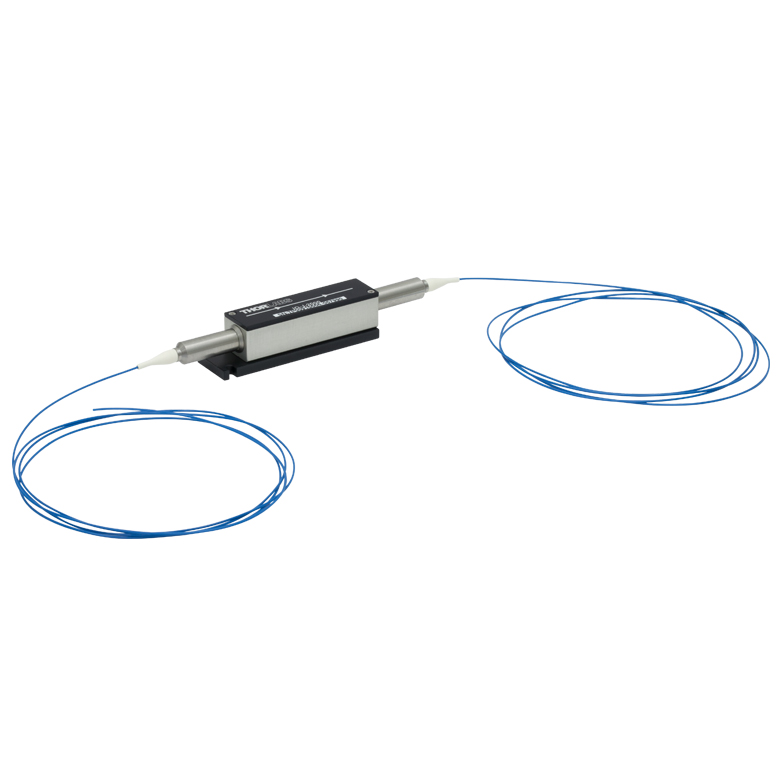 |
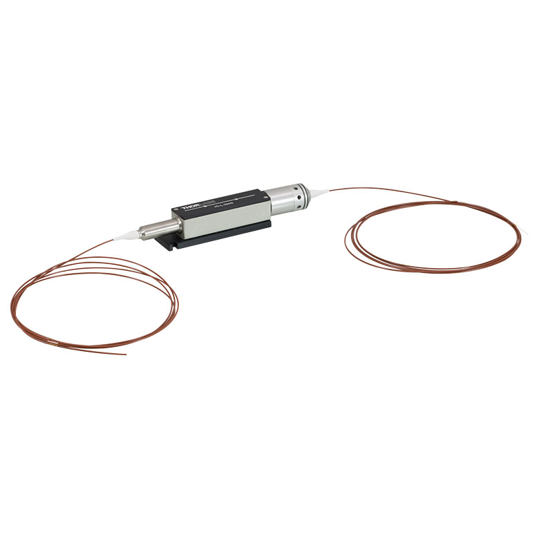 |
| Item #a | IO-J-2000 | IO-L-2000 |
| Fiber Type | PM | PM |
| Polarization Dependence | Fast Axis Blocked | Fast Axis Blocked |
| Isolator Design | Single Stage | Single Stage |
| Center Wavelength | 2000 nm | 2000 nm |
| Operating Range | 1990 - 2010 nm | 1990 - 2010 nm |
| Max Powerb,c (Without Connectors) |
3 W (CW)d | 10 W (CW)e |
| Isolationf | 28 dB (Min) 30 dB (Typ.) |
28 dB (Min) 30 dB (Typ.) |
| Performance Graph (Click for Plot) |
 |
 |
| Insertion Loss | 1.0 dB (Typ.) 1.2 dB (Max) |
1.6 dB (Typ.) 1.6 dB (Max) |
| Polarization Extinction Ratio (PER) | ≥18 dB | ≥20 dB |
| Return Loss | ≥50 dB | ≥50 dB |
| Fiber | PM2000 | PM2000 |