 Products Home / Optical Fiber & Fiber Patch Cables / Single Mode Fiber Optic Patch Cables / Single Mode FC/APC Fiber Optic Patch Cables
Single Mode FC/APC Fiber Optic Patch Cables
- SM Patch Cables for 320 to 2200 nm
- FC/APC Connectors Reduce Back Reflections
- Low Back Reflections: 60 dB (Typ.)
- Custom Cables Also Available
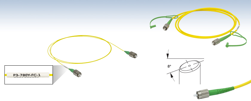
One End Labeled
with Part Number
for Easy Identification
P3-780Y-FC-1
780 - 970 nm Cable,
Ø900 µm Hytrel® Jacket,
1 m Long
P3-405B-FC-1
488 - 633 nm Cable, Ø3 mm PVC Jacket, 1 m Long
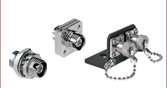
FC/APC Connector


Please Wait
| Stock Single Mode Patch Cables Selection Guide | |
|---|---|
| Standard Cables | FC/PC to FC/PC |
| FC/APC to FC/APC | |
| Hybrid | |
| AR-Coated Patch Cables | |
| TEC Single Mode AR-Coated Patch Cables | |
| HR-Coated Patch Cables | |
| Beamsplitter-Coated Patch Cables | |
| MIR Fluoride Fiber Patch Cables | |
Features
- FC/APC Narrow Key (2.0 mm) Connectors
- High Return Loss (Low Back Reflection) of 60 dB (Typical)
- 0.3 dB Connector to Connector Loss for Telecom Wavelengths
- Available from Stock
- Cables with Ø3 mm or Ø900 µm Jackets Available
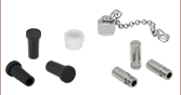
- Two Dust Caps Included
These single mode fiber optic patch cables are FC/APC terminated on both ends, making them ideal for systems that are sensitive to back reflections. The narrow key connector utilizes a ferrule that has an 8° angle polished tip, ensuring typical return loss of 60 dB. Each cable is FC/APC terminated on both ends, and cables are available in 1, 2, 5, or 10 m lengths. Cables with a Ø3 mm jacket come with 30126A3 connectors, while the Ø900 µm jacketed cables come with 30126A9 connectors. The thinner profile of the Ø900 µm jacketed cables with Hytrel®* furcation tubing allows them to be used with our Manual Fiber Polarization Controllers.
Each patch cable includes two protective caps that shield the ferrule ends from dust and other hazards. Additional CAPF Plastic Fiber Caps and CAPFM Threaded Metal Caps for FC/APC-terminated ends are also sold separately. Mating sleeves are available to connect FC/APC to FC/APC connectors. These mating sleeves minimize back reflections and ensure proper alignment of the cores of each terminated fiber end.
Thorlabs also offers AR-Coated Single Mode Patch Cables, which have an antireflective coating on one fiber end for higher performance in fiber-to-free space applications. If you cannot find the appropriate stock patch cable your application requires, Thorlabs also offers custom patch cables with same-day shipping.
*Hytrel® is a registered trademark of DuPont Polymers, Inc.
| Item # Prefix | P3-305A-FC | P3-405Y-FC | P3-405-FC | P3-405B-FC | P3-460Y-FC | P3-460B-FC |
|---|---|---|---|---|---|---|
| Fiber | SM300 | S405-XP | SM400 | SM450 | ||
| Operating Wavelength | 320 - 430 nm | 400 - 680 nm | 405 - 532 nm | 488 - 633 nma | ||
| Cutoff Wavelength | ≤310 nm | 380 ± 20 nm | 305 - 400 nm | 350 - 470 nma | ||
| Mode Field Diameter (MFD)c |
2.0 - 2.4 µm @ 350 nm |
3.3 ± 0.5 µm @ 405 nm 4.6 ± 0.5 µm @ 630 nm |
2.5 - 3.4 µm @ 480 nm |
2.8 - 4.1 µm @ 488 nm | ||
| Cladding Diameter | 125 ± 1.0 µm | 125 ± 1.0 µm | 125 ± 1.0 µm | 125 ± 1.0 µm | ||
| Coating Diameter | 245 ± 15 µm | 245 ± 15 µm | 245 ± 15 µm | 245 ± 15 µm | ||
| Attenuation (Max)d | ≤70 dB/km @ 350 nm |
≤30.0 dB/km @ 630 nm ≤30.0 dB/km @ 488 nm |
≤50 dB/km @ 430 nm ≤30 dB/km @ 532 nm |
≤50 dB/km @ 488 nme | ||
| NA | 0.12 - 0.14 | 0.12 | 0.12 - 0.14 | 0.10 - 0.14 | ||
| Typical Insertion Lossf (Click to Enlarge) |
 |
|||||
| Protective Jacketing | Ø3 mm Yellow PVC Furcation Tubing | Ø900 µm Yellow Hytrel®g Tubing | Ø3 mm Yellow PVC Furcation Tubing | Ø3 mm Yellow PVC Furcation Tubing | Ø900 µm Yellow Hytrel®g Tubing | Ø3 mm Yellow PVC Furcation Tubing |
| Return Loss | 60 dB Typical | |||||
| Connectors | FC/APC 2.0 mm Narrow Key | |||||
| Lengthh | 1 m (Item #s Ending In -1) 2 m (Item #s Ending In -2) 5 m (Item #s Ending In -5) 10 m (Item #s Ending In -10) |
|||||
| Item # Prefix | P3-S630Y-FC | P3-S630-FC | P3-630Y-FC | P3-630A-FC | P3-780Y-FC | P3-780A-FC |
|---|---|---|---|---|---|---|
| Fiber | S630-HP | SM600 | 780HP | |||
| Operating Wavelength | 630 - 860 nm | 633 - 780 nmb | 780 - 970 nm | |||
| Cutoff Wavelength | 590 ± 30 nm | 500 - 600 nm | 730 ± 30 nm | |||
| Mode Field Diameter (MFD)c |
4.2 ± 0.5 µm @ 630 nm | 3.6 - 5.3 µm @ 633 nm | 5.0 ± 0.5 µm @ 850 nm | |||
| Cladding Diameter | 125 ± 1.0 µm | 125 ± 1.0 µm | 125 ± 1 µm | |||
| Coating Diameter | 245 ± 15 µm | 245 ± 15 µm | 245 ± 15 µm | |||
| Attenuation (Max)d | ≤10 dB/km @ 630 nm | ≤15 dB/kme | <3.5 dB/km @ 850 nm | |||
| NA | 0.12 | 0.10 - 0.14 | 0.13 | |||
| Typical Insertion Lossf (Click to Enlarge) |
|
|||||
| Protective Jacketing | Ø900 µm Yellow Hytrel®g Tubing | Ø3 mm Yellow PVC Furcation Tubing | Ø900 µm Yellow Hytrel® Tubing | Ø3 mm Yellow PVC Furcation Tubing | Ø900 µm Yellow Hytrel® Tubing | Ø3 mm Yellow PVC Furcation Tubing |
| Return Loss | 60 dB Typical | |||||
| Connectors | FC/APC 2.0 mm Narrow Key | |||||
| Lengthh | 1 m (Item #s Ending In -1) 2 m (Item #s Ending In -2) 5 m (Item #s Ending In -5) 10 m (Item #s Ending In -10) |
|||||
| Item # Prefix | P3-830A-FC | P3-980A-FC | P3-1064Y-FC | P3-SMF28Y-FC | P3-SMF28E-FC | P3-1550A-FC | P3-1950-FC |
|---|---|---|---|---|---|---|---|
| Fiber | SM800-5.6-125 | SM980-5.8-125 | HI1060-J9 | SMF-28 Ultra | 1550BHP | SM1950 | |
| Operating Wavelength | 830 - 980 nm | 980 - 1550 nm | 980 - 1650 nm | 1260 - 1625 nm | 1460 - 1620 nm | 1850 - 2200 nm | |
| Cutoff Wavelength | 660 - 800 nm | 870 - 970 nm | 920 ± 50 nm | <1260 nm | 1400 ± 50 nm | 1720 ± 80 nm | |
| Mode Field Diameter (MFD)a |
4.7 - 6.9 µm @ 830 nm |
5.3 - 6.4 µm @ 980 nm |
5.9 ± 0.3 µm @ 980 nm 6.2. ± 0.3 µm @ 1060 nm |
9.2 ± 0.4 µm @ 1310 nm 10.5 ± 0.5 µm @ 1550 nm |
9.5 ± 0.5 µm @ 1550 nm | 8.0 µm @ 1950 nm | |
| Cladding Diameter | 125 ± 1.0 µm | 125 ± 1.0 µm | 125 ± 0.5 µm | 125 ± 0.7 µm | 125 ± 1 µm | 125 ± 1 µm | |
| Coating Diameter |
245 ± 15 µm | 245 ± 15 µm | 245 ± 10 µm | 242 ± 5 µm | 245 ± 15 µm | 245 ± 10 µm | |
| Attenuationb | <5 dB/kmc (Max) | ≤2.0 dB/kmc (Max) | ≤2.1 dB/km @ 980 nm (Max) ≤1.5 dB/km @ 1060 nm (Max) |
≤0.32 dB/km @ 1310 nm (Max) ≤0.18 dB/km @ 1550 nm (Max) |
≤0.5 dB/km @ 1550 nm (Max) | 5 dB/km @ 1900 nm (Typical) | |
| NA | 0.10 - 0.14 | 0.13 - 0.15 | 0.14 | 0.14 | 0.13 | 0.20 | |
| Typical Insertion Lossd (Click to Enlarge) |
|
||||||
| Protective Jacketing | Ø3 mm Yellow PVC Furcation Tubing | Ø900 µm Yellow Hytrel®e Tubing |
Ø900 µm Yellow Hytrel® Tubing | Ø3 mm Yellow PVC Furcation Tubing | Ø3 mm Yellow PVC Furcation Tubing | ||
| Return Loss | 60 dB Typical | ||||||
| Connectors | FC/APC 2.0 mm Narrow Key | ||||||
| Lengthf | 1 m (Item #s Ending In -1) 2 m (Item #s Ending In -2) 5 m (Item #s Ending In -5) 10 m (Item #s Ending In -10) |
||||||
Click to Enlarge
Figure 56B Mating Between a Narrow-Key Mating Sleeve and Connector
Click to Enlarge
Figure 56A Mating Between a Wide-Key Mating Sleeve and Connector
FC/PC and FC/APC Patch Cable Key Alignment
FC/PC and FC/APC Patch Cables are equipped with either a 2.0 mm narrow or 2.2 mm wide alignment key that fits into a corresponding slot on a mated component. These keys and slots are essential to correctly align the cores of connected fiber patch cables and minimize the insertion loss of the connection.
As an example, Thorlabs designs and manufactures mating sleeves for FC/PC- and FC/APC-terminated patch cables to precise specifications that ensure good alignment when used correctly. To ensure the best alignment, the alignment key on the patch cable is inserted into the corresponding narrow or wide-key slot on the mating sleeve.
Wide-Key-Slot Mating Sleeves
2.2 mm wide-key-slot mating sleeves are compatible with both wide-key and narrow-key connectors. However, using a narrow-key connector in a wide-key slot will allow the connector to rotate slightly in the mating sleeve (as shown in Video 56C). While this configuration is acceptable for patch cables with FC/PC connectors, for FC/APC applications, we recommend using narrow-key-slot mating sleeves to ensure optimum alignment.
Narrow-Key-Slot Mating Sleeves
2.0 mm narrow-key-slot mating sleeves allow for optimal alignment of angled, narrow-key FC/APC connectors, as shown in Video 56D. Therefore, they are not compatible with connectors that have a 2.2 mm wide key. Please note that all FC/PC and FC/APC patch cables manufactured by Thorlabs use narrow key connectors.
Once a narrow key connector is inserted into a narrow-key-slot mating sleeve, the connector will not rotate. We therefore recommend these mating sleeves for FC/PC and FC/APC connectors with narrow keys.
When a narrow key connector is inserted into a wide-key-slot mating sleeve, the connector has room to rotate. For narrow key FC/PC connectors, this is acceptable, but for narrow key FC/APC connectors, significant coupling losses will result.
| Quick Links |
|---|
| Damage at the Air / Glass Interface |
| Intrinsic Damage Threshold |
| Preparation and Handling of Optical Fibers |
Laser-Induced Damage in Silica Optical Fibers
The following tutorial details damage mechanisms relevant to unterminated (bare) fiber, terminated optical fiber, and other fiber components from laser light sources. These mechanisms include damage that occurs at the air / glass interface (when free-space coupling or when using connectors) and in the optical fiber itself. A fiber component, such as a bare fiber, patch cable, or fused coupler, may have multiple potential avenues for damage (e.g., connectors, fiber end faces, and the device itself). The maximum power that a fiber can handle will always be limited by the lowest limit of any of these damage mechanisms.
While the damage threshold can be estimated using scaling relations and general rules, absolute damage thresholds in optical fibers are very application dependent and user specific. Users can use this guide to estimate a safe power level that minimizes the risk of damage. Following all appropriate preparation and handling guidelines, users should be able to operate a fiber component up to the specified maximum power level; if no maximum is specified for a component, users should abide by the "practical safe level" described below for safe operation of the component. Factors that can reduce power handling and cause damage to a fiber component include, but are not limited to, misalignment during fiber coupling, contamination of the fiber end face, or imperfections in the fiber itself. For further discussion about an optical fiber’s power handling abilities for a specific application, please contact Thorlabs’ Tech Support.
Damage at the Air / Glass Interface
There are several potential damage mechanisms that can occur at the air / glass interface. Light is incident on this interface when free-space coupling or when two fibers are mated using optical connectors. High-intensity light can damage the end face leading to reduced power handling and permanent damage to the fiber. For fibers terminated with optical connectors where the connectors are fixed to the fiber ends using epoxy, the heat generated by high-intensity light can burn the epoxy and leave residues on the fiber facet directly in the beam path.
| Table 36C Estimated Optical Power Densities on Air / Glass Interfacea | ||
|---|---|---|
| Type | Theoretical Damage Thresholdb | Practical Safe Levelc |
| CW (Average Power) |
~1 MW/cm2 | ~250 kW/cm2 |
| 10 ns Pulsed (Peak Power) |
~5 GW/cm2 | ~1 GW/cm2 |
Damage Mechanisms on the Bare Fiber End Face
Damage mechanisms on a fiber end face can be modeled similarly to bulk optics, and industry-standard damage thresholds for UV Fused Silica substrates can be applied to silica-based fiber. However, unlike bulk optics, the relevant surface areas and beam diameters involved at the air / glass interface of an optical fiber are very small, particularly for coupling into single mode (SM) fiber. therefore, for a given power density, the power incident on the fiber needs to be lower for a smaller beam diameter.
Table 36C lists two thresholds for optical power densities: a theoretical damage threshold and a "practical safe level". In general, the theoretical damage threshold represents the estimated maximum power density that can be incident on the fiber end face without risking damage with very good fiber end face and coupling conditions. The "practical safe level" power density represents minimal risk of fiber damage. Operating a fiber or component beyond the practical safe level is possible, but users must follow the appropriate handling instructions and verify performance at low powers prior to use.
Calculating the Effective Area for Single Mode Fibers
The effective area for single mode (SM) fiber is defined by the mode field diameter (MFD), which is the cross-sectional area through which light propagates in the fiber; this area includes the fiber core and also a portion of the cladding. To achieve good efficiency when coupling into a single mode fiber, the diameter of the input beam must match the MFD of the fiber.
As an example, SM400 single mode fiber has a mode field diameter (MFD) of ~Ø3 µm operating at 400 nm, while the MFD for SMF-28 Ultra single mode fiber operating at 1550 nm is Ø10.5 µm. The effective area for these fibers can be calculated as follows:
SM400 Fiber: Area = Pi x (MFD/2)2 = Pi x (1.5 µm)2 = 7.07 µm2 = 7.07 x 10⁻⁸ cm2
SMF-28 Ultra Fiber: Area = Pi x (MFD/2)2 = Pi x (5.25 µm)2 = 86.6 µm2 = 8.66 x 10⁻⁷ cm2
To estimate the power level that a fiber facet can handle, the power density is multiplied by the effective area. Please note that this calculation assumes a uniform intensity profile, but most laser beams exhibit a Gaussian-like shape within single mode fiber, resulting in a higher power density at the center of the beam compared to the edges. Therefore, these calculations will slightly overestimate the power corresponding to the damage threshold or the practical safe level. Using the estimated power densities assuming a CW light source, we can determine the corresponding power levels as:
SM400 Fiber: 7.07 x 10⁻⁸ cm2 x 1 MW/cm2 = 7.1 x 10⁻⁸ MW = 71 mW (Theoretical Damage Threshold)
7.07 x 10⁻⁸ cm2 x 250 kW/cm2 = 1.8 x 10⁻⁵ kW = 18 mW (Practical Safe Level)
SMF-28 Ultra Fiber: 8.66 x 10⁻⁷ cm2 x 1 MW/cm2 = 8.7 x 10⁻⁷ MW = 870 mW (Theoretical Damage Threshold)
8.66 x 10⁻⁷ cm2 x 250 kW/cm2 = 2.1 x 10⁻⁴ kW = 210 mW (Practical Safe Level)
Effective Area of Multimode Fibers
The effective area of a multimode (MM) fiber is defined by the core diameter, which is typically far larger than the MFD of an SM fiber. For optimal coupling, Thorlabs recommends focusing a beam to a spot roughly 70 - 80% of the core diameter. The larger effective area of MM fibers lowers the power density on the fiber end face, allowing higher optical powers (typically on the order of kilowatts) to be coupled into multimode fiber without damage.
Damage Mechanisms Related to Ferrule / Connector Termination
 Click to Enlarge
Figure 36D Plot showing approximate input power that can be incident on a single mode silica optical fiber with a termination. Each line shows the estimated power level due to a specific damage mechanism. The maximum power handling is limited by the lowest power level from all relevant damage mechanisms (indicated by a solid line).
Fibers terminated with optical connectors have additional power handling considerations. Fiber is typically terminated using epoxy to bond the fiber to a ceramic or steel ferrule. When light is coupled into the fiber through a connector, light that does not enter the core and propagate down the fiber is scattered into the outer layers of the fiber, into the ferrule, and the epoxy used to hold the fiber in the ferrule. If the light is intense enough, it can burn the epoxy, causing it to vaporize and deposit a residue on the face of the connector. This results in localized absorption sites on the fiber end face that reduce coupling efficiency and increase scattering, causing further damage.
For several reasons, epoxy-related damage is dependent on the wavelength. In general, light scatters more strongly at short wavelengths than at longer wavelengths. Misalignment when coupling is also more likely due to the small MFD of short-wavelength SM fiber that also produces more scattered light.
To minimize the risk of burning the epoxy, fiber connectors can be constructed to have an epoxy-free air gap between the optical fiber and ferrule near the fiber end face. Our high-power multimode fiber patch cables use connectors with this design feature.
Determining Power Handling with Multiple Damage Mechanisms
When fiber cables or components have multiple avenues for damage (e.g., fiber patch cables), the maximum power handling is always limited by the lowest damage threshold that is relevant to the fiber component. In general, this represents the highest input power that can be incident on the patch cable end face and not the coupled output power.
As an illustrative example, Figure 36D shows an estimate of the power handling limitations of a single mode fiber patch cable due to damage to the fiber end face and damage via an optical connector. The total input power handling of a terminated fiber at a given wavelength is limited by the lower of the two limitations at any given wavelength (indicated by the solid lines). A single mode fiber operating at around 488 nm is primarily limited by damage to the fiber end face (blue solid line), but fibers operating at 1550 nm are limited by damage to the optical connector (red solid line).
In the case of a multimode fiber, the effective mode area is defined by the core diameter, which is larger than the effective mode area for SM fiber. This results in a lower power density on the fiber end face and allows higher optical powers (on the order of kilowatts) to be coupled into the fiber without damage (not shown in graph). However, the damage limit of the ferrule / connector termination remains unchanged and as a result, the maximum power handling for a multimode fiber is limited by the ferrule and connector termination.
Please note that these are rough estimates of power levels where damage is very unlikely with proper handling and alignment procedures. It is worth noting that optical fibers are frequently used at power levels above those described here. However, these applications typically require expert users and testing at lower powers first to minimize risk of damage. Even still, optical fiber components should be considered a consumable lab supply if used at high power levels.
Intrinsic Damage Threshold
In addition to damage mechanisms at the air / glass interface, optical fibers also display power handling limitations due to damage mechanisms within the optical fiber itself. These limitations will affect all fiber components as they are intrinsic to the fiber itself. Two categories of damage within the fiber are damage from bend losses and damage from photodarkening.
Bend Losses
Bend losses occur when a fiber is bent to a point where light traveling in the core is incident on the core/cladding interface at an angle higher than the critical angle, making total internal reflection impossible. Under these circumstances, light escapes the fiber, often in a localized area. The light escaping the fiber typically has a high power density, which burns the fiber coating as well as any surrounding furcation tubing.
A special category of optical fiber, called double-clad fiber, can reduce the risk of bend-loss damage by allowing the fiber’s cladding (2nd layer) to also function as a waveguide in addition to the core. By making the critical angle of the cladding/coating interface higher than the critical angle of the core/clad interface, light that escapes the core is loosely confined within the cladding. It will then leak out over a distance of centimeters or meters instead of at one localized spot within the fiber, minimizing the risk of damage. Thorlabs manufactures and sells 0.22 NA double-clad multimode fiber, which boasts very high, megawatt range power handling.
Photodarkening
A second damage mechanism, called photodarkening or solarization, can occur in fibers used with ultraviolet or short-wavelength visible light, particularly those with germanium-doped cores. Fibers used at these wavelengths will experience increased attenuation over time. The mechanism that causes photodarkening is largely unknown, but several fiber designs have been developed to mitigate it. For example, fibers with a very low hydroxyl ion (OH) content have been found to resist photodarkening and using other dopants, such as fluorine, can also reduce photodarkening.
Even with the above strategies in place, all fibers eventually experience photodarkening when used with UV or short-wavelength light, and thus, fibers used at these wavelengths should be considered consumables.
Preparation and Handling of Optical Fibers
General Cleaning and Operation Guidelines
These general cleaning and operation guidelines are recommended for all fiber optic products. Users should still follow specific guidelines for an individual product as outlined in the support documentation or manual. Damage threshold calculations only apply when all appropriate cleaning and handling procedures are followed.
-
All light sources should be turned off prior to installing or integrating optical fibers (terminated or bare). This ensures that focused beams of light are not incident on fragile parts of the connector or fiber, which can possibly cause damage.
-
The power-handling capability of an optical fiber is directly linked to the quality of the fiber/connector end face. Always inspect the fiber end prior to connecting the fiber to an optical system. The fiber end face should be clean and clear of dirt and other contaminants that can cause scattering of coupled light. Bare fiber should be cleaved prior to use and users should inspect the fiber end to ensure a good quality cleave is achieved.
-
If an optical fiber is to be spliced into the optical system, users should first verify that the splice is of good quality at a low optical power prior to high-power use. Poor splice quality may increase light scattering at the splice interface, which can be a source of fiber damage.
-
Users should use low power when aligning the system and optimizing coupling; this minimizes exposure of other parts of the fiber (other than the core) to light. Damage from scattered light can occur if a high power beam is focused on the cladding, coating, or connector.
Tips for Using Fiber at Higher Optical Power
Optical fibers and fiber components should generally be operated within safe power level limits, but under ideal conditions (very good optical alignment and very clean optical end faces), the power handling of a fiber component may be increased. Users must verify the performance and stability of a fiber component within their system prior to increasing input or output power and follow all necessary safety and operation instructions. The tips below are useful suggestions when considering increasing optical power in an optical fiber or component.
-
Splicing a fiber component into a system using a fiber splicer can increase power handling as it minimizes possibility of air/fiber interface damage. Users should follow all appropriate guidelines to prepare and make a high-quality fiber splice. Poor splices can lead to scattering or regions of highly localized heat at the splice interface that can damage the fiber.
-
After connecting the fiber or component, the system should be tested and aligned using a light source at low power. The system power can be ramped up slowly to the desired output power while periodically verifying all components are properly aligned and that coupling efficiency is not changing with respect to optical launch power.
-
Bend losses that result from sharply bending a fiber can cause light to leak from the fiber in the stressed area. When operating at high power, the localized heating that can occur when a large amount of light escapes a small localized area (the stressed region) can damage the fiber. Avoid disturbing or accidently bending fibers during operation to minimize bend losses.
-
Users should always choose the appropriate optical fiber for a given application. For example, large-mode-area fibers are a good alternative to standard single mode fibers in high-power applications as they provide good beam quality with a larger MFD, decreasing the power density on the air/fiber interface.
-
Step-index silica single mode fibers are normally not used for ultraviolet light or high-peak-power pulsed applications due to the high spatial power densities associated with these applications.
| Posted Comments: | |
Héctor Álvarez Martínez
(posted 2024-02-20 09:10:36.727) Good morning,
I have a couple of questions:
1/ What makes the P3-SMF28E-FC-5 cheaper than the P3-1550A-FC-5. Naively, I would think that the SMF28 one is better (and it should be more expensive) since it covers a wider wavelength range and shows less attennuation. What are the hidden parameters that I am missing and are making the second fiber better/more expensive?
2/ Is it possible to have these two fibers for a 50 m length?
Thanks in advance,
Héctor cdolbashian
(posted 2024-03-05 03:16:28.0) Thank you for reaching out to us with this inquiry. I have contacted you directly to discuss pricing inquiries. Regarding the 50m length of fiber, you can order it directly here: https://www.thorlabs.com/newgrouppage9.cfm?objectgroup_id=2410 Cheng Hung
(posted 2023-12-07 18:10:35.613) Which FC/APC Fiber Connectors: Single Mode should I buy for P3-780Y-FC-1? cdolbashian
(posted 2023-12-13 03:32:14.0) Thank you for reaching out to us with this inquiry. The part you are referencing is a patch cable, and thus is already connectorized. If you have a specific application-based concern, I am happy to discuss it with you. I have contacted you directly to inquire about your specific needs and how we can help you achieve your requirements. Conner Phillips
(posted 2023-07-11 09:15:01.453) Hi, do you have any data on how the P3-1550A-FC performs up to 1690 nm?
We have an application with the bandwidth 1450-1690 nm and this appears the best fitting off-the-shelf fiber in your selection. jdelia
(posted 2023-07-13 01:32:46.0) Thank you for contacting Thorlabs. Unfortunately, we have not taken any test data at this wavelength and cannot make any guarantees regarding its performance outside of the operating wavelength range. We apologize for the inconvenience. Aleksandra Kroh
(posted 2023-04-11 07:44:04.313) Dear Sir or Madam,
I was wondering if this PMF would be also available in 50 cm length. I would be very grateful if you could also name the price.
Best regards
Aleksandra Kroh jgreschler
(posted 2023-04-11 09:05:38.0) Thank you for reaching out to Thorlabs. We absolutely can quote you for this through our custom patch cable calculator here: https://www.thorlabs.us/newgrouppage9.cfm?objectgroup_id=2410. You simply need to put in your configuration and it will give you the price and lead time for production. Alternatively you can request a formal pdf quote by emailing techsupport@thorlabs.com. Boyi Zhang
(posted 2022-12-14 10:41:26.013) Hi, Dear Sir or Madam,
I want to buy some fibers but one question here.
P3-SMF28E-FC and P3-1550A-FC is confusing to me.
Why the previous one has wider working wavelength range but cheaper?
What is the difference between them?
Best regards,
Boyi cdolbashian
(posted 2022-12-28 10:20:45.0) Thank you for reaching out to us Boyi. While these fibers appear to both fill the same role, it seems like there are certain situations where one would be preferred to the other, and in this sense, they should not be compared directly to each other price-wise. I have reached out to you directly to discuss this with you in an attempt to find the best suited component for your application. Tommaso Marcato
(posted 2022-07-22 12:59:05.413) Dear Mr./Ms., Is it possible to know the MFD of the P3-460Y-FC fiber at 532 nm? I'd like to be able to estimate more exactly the focal length required for the fiber collimator but I can only find the specs at 488 nm which have a pretty big range. Thanks! Kim Soon Lee
(posted 2022-05-09 13:16:51.03) I would like to have a 5m long such as P3-2000-FC-5, both connectors shall be FC/APC, for the 1950nm wavelength.
Do you have such a length? jgreschler
(posted 2022-05-09 09:42:29.0) Thank you for reaching out to Thorlabs. Custom configurations of existing stock products can be requested by contacting techsupport@thorlabs.com. I have reached out to you directly to discuss this further. bharathi R
(posted 2020-09-18 05:20:23.26) Sir, I need corning SMF-28 fiber with pigtailed FC APC connector. Whether it is pure silica or doped YLohia
(posted 2020-09-18 09:49:48.0) Thank you for contacting Thorlabs. The SMF-28 fiber contains a Germanium-doped core. srikanth
(posted 2018-09-16 08:27:30.27) For HI1060-J9 , please confirm whether the 900um hytrel jacket is in loose tube form or hard coating form. YLohia
(posted 2018-09-24 11:35:28.0) Hello, thank you for contacting Thorlabs. The HI1060-J9 is not a loose tube, but instead is a "tight-buffer" jacket. Tight buffer jacketing is not fixed/adhered to the fiber as it would be difficult to strip without breaking the fiber. nhatquang85
(posted 2018-05-24 01:33:45.817) Dear Mr./Mrs.
Would you please provide the 100 m fiber for this type of fiber?
P3-SMF28E-FC-100 - Single Mode Fiber Patch Cable, 100 m, 1260 nm - 1625 nm, FC/APC
Best,
JO YLohia
(posted 2018-05-24 08:55:55.0) Hello Jo, please use our online custom fiber ordering tool (https://www.thorlabs.com/newgrouppage9.cfm?objectgroup_id=2410) to configure your patch cable. Be sure to enter "SMF-28-J9" as the fiber type. zeuner
(posted 2016-08-05 02:01:09.63) Hej, I would like to compare the attenution of 780HP and SM800 fibers at 900nm. Could you send me some data for this? Thanks a lot! Best, Katharina sunzhe
(posted 2015-06-16 12:09:45.203) Dear Mr./Mrs,
For this kind of single mode FC/APC fiber, you only provide 3 kinds of length (1m,2m,5m). If I need 0.5m, do you have a special offer?
Best,
Zhe Sun cdaly
(posted 2015-07-30 03:17:32.0) Response from Chris at Thorlabs: For non-standard lengths as well as other custom configurations, these fibers can be ordered through our custom patch cable configuration tool found at this address:
http://www.thorlabs.com/newgrouppage9.cfm?objectgroup_id=2410 julien.houel
(posted 2014-10-30 16:44:40.493) Hello,
I am using P3-460B-FC-5+SM05FCAb+CP1xy.
It seems that I never manage to get a perfectly straight beam out of this assembly. Whenever I want to couple light back with a mirror, the light does not go through the center of my correctly placed irises. And when the light goes through the center of the irises, it is not reflected back correctly in the fiber.
I suspect something's going on with the angle of the light beam out of the assembly, because of the APC termination. Is there any record of such an issue?
Tanks for your answer. jlow
(posted 2014-10-30 01:35:46.0) Response from Jeremy at Thorlabs: Due to the tolerance of the bulkhead, there can be a very slight angle from the output. This can be taken care with the use of a kinematic mount. I will contact you directly with more details. jhyuan
(posted 2013-04-20 21:00:01.75) Hi,
I'm using PAFA-X-4-A to couple 514nm laser to
P3-460A-FC-2. I can only get 10% efficiency at the best, and I saw a halo of laser light coming off the cable, decaying along the length of the cable. Is that halo normal? I have no previous experience with single mode fiber, and thought there should not be any light coming off the cable? Am I wrong, or is the fiber somehow damaged?
Thank you for you help!
Junhua tcohen
(posted 2013-04-25 15:51:00.0) Response from Tim at Thorlabs to Junhua: From your description it sounds that the spot is not being optimally coupled into the fiber. If it is leaking into the cladding on coupling and therefore not being totally internally reflected, you can often see this power exiting. This is also possible if you are bending your fiber with too small of a radius. We will contact you directly to troubleshoot. |
- Negligible Photodarkening
- Dual Acrylate Coating
| Item # Prefix | Fiber Type | Operating Wavelength | Cutoff Wavelength | Mode Field Diameter | Cladding Diameter | Coating Diameter | Max Attenuationa |
NA | Connectors | Jacket |
|---|---|---|---|---|---|---|---|---|---|---|
| P3-305A-FC | SM300 | 320 - 430 nm | ≤310 nm | 2.0 - 2.4 µm @ 350 nm |
125 ± 1.0 µm | 245 ± 15 µm | ≤70 dB/km @ 350 nm |
0.12 - 0.14 | FC/APC, 2.0 mm Narrow Key |
Ø3 mm Yellow PVC Furcation Tubing |
| Item # Prefix | Fiber Type | Operating Wavelength |
Cutoff Wavelength |
Mode Field Diameter |
Cladding Diameter |
Coating Diameter |
Max Attenuationa |
NA | Connectors | Jacket |
|---|---|---|---|---|---|---|---|---|---|---|
| P3-405Y-FC | S405-XP | 400 - 680 nm | 380 ± 20 nm | 3.3 ± 0.5 µm @ 405 nm 4.6 ± 0.5 µm @ 630 nm |
125 ± 1.0 µm | 245 ± 15 µm | ≤30.0 dB/km @ 630 nm ≤30.0 dB/km @ 488 nm |
0.12 | FC/APC, 2.0 mm Narrow Key | Ø900 µm Yellow Hytrel®b Tubing |
| P3-405-FC | Ø3 mm Yellow PVC Furcation Tubing |
| Item # Prefix | Fiber Type | Operating Wavelength |
Cutoff Wavelength |
Mode Field Diameter |
Cladding Diameter |
Coating Diameter |
Max Attenuationa |
NA | Connectors | Jacket |
|---|---|---|---|---|---|---|---|---|---|---|
| P3-405B-FC | SM400 | 405 - 532 nm | 305 - 400 nm | 2.5 - 3.4 µm @ 480 nm |
125 ± 1.0 µm | 245 ± 15 µm | ≤50 dB/km @ 430 nm ≤30 dB/km @ 532 nm |
0.12 - 0.14 | FC/APC, 2.0 mm Narrow Key |
Ø3 mm Yellow PVC Furcation Tubing |
| Item # Prefix | Fiber Type | Operating Wavelengtha |
Cutoff Wavelengtha |
Mode Field Diameter |
Cladding Diameter |
Coating Diameter |
Max Attenuationb |
NA | Connectors | Jacket |
|---|---|---|---|---|---|---|---|---|---|---|
| P3-460Y-FC | SM450 | 488 - 633 nm | 350 - 470 nm | 2.8 - 4.1 µm @ 488 nm |
125 ± 1.0 µm | 245 ± 15 µm | ≤50 dB/km @ 488 nm |
0.10 - 0.14 | FC/APC, 2.0 mm Narrow Key |
Ø900 µm Yellow Hytrel®c Tubing |
| P3-460B-FC | Ø3 mm Yellow PVC Furcation Tubing |
| Item # Prefix | Fiber Type | Operating Wavelength |
Cutoff Wavelength |
Mode Field Diameter |
Cladding Diameter |
Coating Diameter |
Max Attenuationa |
NA | Connectors | Jacket |
|---|---|---|---|---|---|---|---|---|---|---|
| P3-S630Y-FC | S630-HP | 630 - 860 nm | 590 ± 30 nm | 4.2 ± 0.5 µm @ 630 nm | 125 ± 1.0 µm | 245 ± 15 µm | ≤10 dB/km @ 630 nm | 0.12 | FC/APC, 2.0 mm Narrow Key |
Ø900 µm Yellow Hytrel®b Tubing |
| P3-S630-FC | Ø3 mm Yellow PVC Furcation Tubing |
| Item # Prefix | Fiber Type | Operating Wavelengtha |
Cutoff Wavelength |
Mode Field Diameter |
Cladding Diameter |
Coating Diameter |
Max Attenuationb |
NA | Connectors | Jacket |
|---|---|---|---|---|---|---|---|---|---|---|
| P3-630Y-FC | SM600 | 633 - 780 nm | 500 - 600 nm | 3.6 - 5.3 µm @ 633 nm |
125 ± 1.0 µm | 245 ± 15 µm | ≤15 dB/km @ 633 nm |
0.10 - 0.14 | FC/APC, 2.0 mm Narrow Key |
Ø900 µm Yellow Hytrel®c Tubing |
| P3-630A-FC | Ø3 mm Yellow PVC Furcation Tubing |
| Item # Prefix | Fiber Type | Operating Wavelength |
Cutoff Wavelength |
Mode Field Diameter |
Cladding Diameter |
Coating Diameter |
Max Attenuationa |
NA | Connectors | Jacket |
|---|---|---|---|---|---|---|---|---|---|---|
| P3-780Y-FC | 780HP | 780 - 970 nm | 730 ± 30 nm | 5.0 ± 0.5 µm @ 850 nm |
125 ± 1 µm | 245 ± 15 µm | <3.5 dB/km @ 780 nm | 0.13 | FC/APC, 2.0 mm Narrow Key |
Ø900 µm Yellow Hytrel®b Tubing |
| P3-780A-FC | Ø3 mm Yellow PVC Furcation Tubing |
| Item # Prefix | Fiber Type | Operating Wavlengtha |
Cutoff Wavelength |
Mode Field Diameter |
Cladding Diameter |
Coating Diameter |
Max Attenuationb |
NA | Connectors | Jacket |
|---|---|---|---|---|---|---|---|---|---|---|
| P3-830A-FC | SM800-5.6-125 | 830 - 980 nm | 660 - 800 nm | 4.7 - 6.9 µm @ 830 nm |
125 ± 1.0 µm | 245 ± 15 µm | <5 dB/km | 0.10 - 0.14 | FC/APC, 2.0 mm Narrow Key |
Ø3 mm Yellow PVC Furcation Tubing |
| Item # Prefix | Fiber Type | Operating Wavelengtha |
Cutoff Wavelength |
Mode Field Diameter |
Cladding Diameter |
Coating Diameter |
Max Attenuationb |
NA | Connectors | Jacket |
|---|---|---|---|---|---|---|---|---|---|---|
| P3-980A-FC | SM980-5.8-125 | 980 - 1550 nm | 870 - 970 nm | 5.3 - 6.4 µm @ 980 nm |
125 ± 1.0 µm | 245 ± 15 µm | ≤2.0 dB/km @ 980 nm |
0.13 - 0.15 | FC/APC, 2.0 mm Narrow Key |
Ø3 mm Yellow PVC Furcation Tubing |
| Item # Prefix | Fiber Type | Operating Wavelength |
Cutoff Wavelength |
Mode Field Diameter |
Cladding Diameter |
Coating Diameter |
Max Attenuationa |
NA | Connectors | Jacket |
|---|---|---|---|---|---|---|---|---|---|---|
| P3-1064Y-FC | HI1060-J9 | 980 - 1650 nm | 920 ± 50 nm | 5.9 ± 0.3 µm @ 980 nm 6.2 ± 0.3 µm @ 1060 nm |
125 ± 0.5 µm | 245 ± 10 µm | <2.1 dB/km @ 980 nm <1.5 dB/km @ 1060 nm |
0.14 | FC/APC, 2.0 mm Narrow Key |
Ø900 µm Yellow Hytrel®b Tubing |
| Item # Prefix | Fiber Type | Operating Wavelength |
Cutoff Wavelength |
Mode Field Diameter |
Cladding Diameter |
Coating Diameter |
Max Attenuationa |
NA | Connectors | Jacket |
|---|---|---|---|---|---|---|---|---|---|---|
| P3-SMF28Y-FC | SMF-28 Ultra | 1260 - 1625 nm | <1260 nm | 9.2 ± 0.4 µm @ 1310 nm 10.4 ± 0.5 µm @ 1550 nm |
125 ± 0.7 µm | 242 ± 5 µm | ≤0.32 dB/km @ 1310 nm ≤0.18 dB/km @ 1550 nm |
0.14 | FC/APC, 2.0 mm Narrow Key |
Ø900 µm Yellow Hytrel® Tubing |
| P3-SMF28E-FC | Ø3 mm Yellow PVC Furcation Tubing |
| Item # Prefix | Fiber Type | Operating Wavelength |
Cutoff Wavelength |
Mode Field Diameter |
Cladding Diameter |
Coating Diameter |
Max Attenuationa |
NA | Connectors | Jacket |
|---|---|---|---|---|---|---|---|---|---|---|
| P3-1550A-FC | 1550BHP | 1460 - 1620 nm | 1400 ± 50 nm | 9.5 ± 0.5 µm @ 1550 nm |
125 ± 1 µm | 245 ± 15 µm | 0.5 dB/km @ 1550 nm | 0.13 | FC/APC, 2.0 mm Narrow Key |
Ø3 mm Yellow PVC Furcation Tubing |
| Item # Prefix | Fiber Type | Operating Wavelength |
Cutoff Wavelength |
Mode Field Diameter |
Cladding Diameter |
Coating Diameter |
Typical Attenuationa |
NA | Connectors | Jacket |
|---|---|---|---|---|---|---|---|---|---|---|
| P3-1950-FC | SM1950b | 1850 - 2200 nm | 1720 ± 80 nm | 8.0 µm @ 1950 nm | 125 ± 1 µm | 245 ± 10 µm | 5 dB/km (0.005 dB/m) @ 1.9 µm |
0.20 | FC/APC, 2.0 mm Narrow Key |
Ø3 mm Yellow PVC Furcation Tubing |