 Products Home
Optical Chopper System and Chopper Wheels
- Crystal-Stabilized, Phase-Locked Feedback Loop Suppresses
Low Frequency Drift and Pulse Jitter - Manual, USB, and External Trigger Controller
- 15 Blades Covering Frequencies from 4 Hz to 10 kHz
MC1F10HP
20 Hz - 10 kHz
MC1F2
4 Hz - 200 Hz
MC1F60
120 Hz - 6 kHz
MC1F10A
Adjustable Duty Cycle
MC2F47
MC2F330
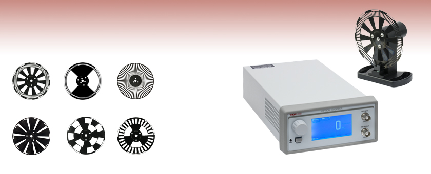
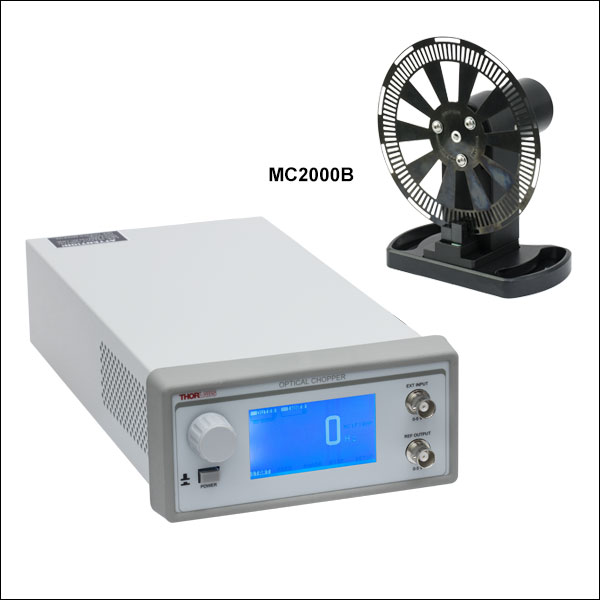
MC2000B
Includes Controller, Chopper Head,
and MC1F10HP Dual-Frequency Blade
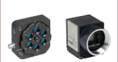
Controller
Chopper Head with MC1F10HP Blade
(Included with MC2000B System)
Harmonic Blades


Please Wait
| Key Specificationsa | |
|---|---|
| Chopping Frequency, with Various Blades |
4 Hz – 10 kHz |
| Frequency Drift | <20 ppm/°C |
| Ext. Reference Compatibility |
TTL/CMOS |
| Frequency Resolution | 0.01 Hz (2 Slot Blades) 0.1 Hz (MC1F10HP, Default Blade) 1 Hz (All Other Blades) |
| External Reference Signal Synchronization | |
| Harmonic | 2 to 15X |
| Subharmonic | 1/2 to 1/15X |
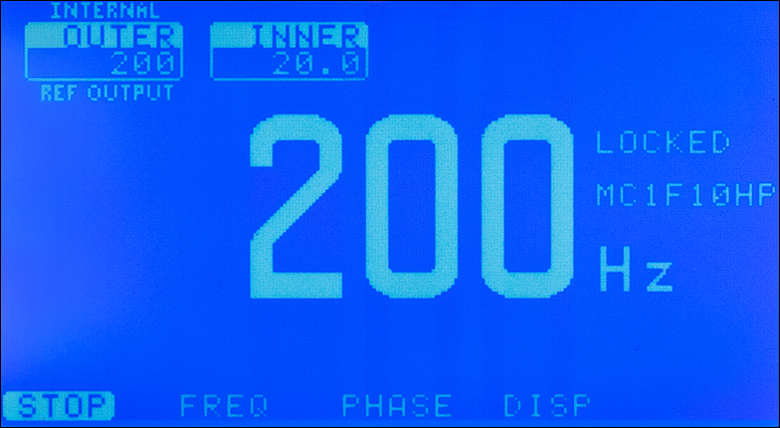
Click to Enlarge
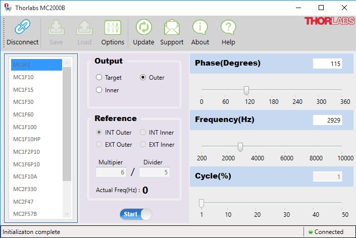
Figure 1.1 Controller Interface Screenshot
Features
- Crystal-Stabilized, Phase-Locked Feedback Loop Suppresses Low Frequency Drift and Phase Jitter
- Harmonic, Subharmonic, and Fractional Harmonic Chopping with Sum and Difference Reference Outputs
- Microprocessor Controlled
- Single- and Dual-Frequency Blades Available
- Harmonic Frequency Blades Available for Pump-Probe and Other Nonlinear Experiments
- Save and Recall User Setups in Non-Volatile RAM
- USB Interface
- Control Software Package Included
The MC2000B Optical Chopper is a precision instrument that utilizes advanced features to modulate light from a continuous beam. The controller uses a phase-locked loop (PLL) motor speed control design to precisely maintain the chopping speed and phase relative to a reference signal. An internal, crystal-stabilized, frequency synthesizer provides an accurate and stable reference frequency for stable long-term performance. The MC2000B Chopper offers faster locking times, interface improvements, and a larger selection of blades than our previous-generation MC2000 Optical Chopper.
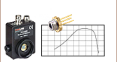
An optical switch is used to get the reference signal when the chopper blades pass through and interrupt the beam path. The switch incorporates an LED with a wavelength range of 850 nm - 940 nm that is operated at the 15 mA threshold current to minimize light output from the LED.
Unlike conventional, open-loop speed control designs, the PLL speed control circuit also allows the MC2000B chopper to be synchronized to external reference signals, including other MC2000B choppers and reference sources such as DSP lock-in amplifiers. Please see the Operations tab for more details on the MC2000B chopper and its applications.
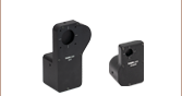
The MC2000B design features a high quality, rare earth magnet, DC motor. The photo-etched optical chopper wheel blade is made of 0.01" thick blued clock spring steel for high precision. The compact optical head has a wide base for extra stability, and the base is slotted for two 1/4"-20 (M6) mounting screws on 3" (76.2 mm) centers. The mounting slots have a 1.5" (38.1 mm) radius. The interface cable uses circular snap-on Hirose connectors for easy setup.
The MC2000B controller includes a 240 x 128 pixel graphics display for setting and monitoring chopper functionality. All of the functions are accessible through a front panel control knob with turn and push control. Multiple user setups can be easily saved and recalled from non-volatile memory. A USB interface is included as a standard feature for remote PC control of the MC2000B. A software package with a GUI to control the MC2000B is included with each controller and can also be downloaded from the Software tab. The package also supports controlling the MC2000B via programs written in C++ or LabVIEW.
Please Note: The MC2000B should be shielded from stray light sources because light contamination in the optical sensor will cause jitter.
| Chopper Blade Specificationsa | |||||
|---|---|---|---|---|---|
| Item # | Chopping Frequency | Duty Cycle | Max Phase Jitter (RMS, @ One Blade Rotation) |
Slots | Slot Angle |
| Single and Dual Frequency Blades | |||||
| MC1F10HP (Included with MC2000B)b |
Inner: 20 Hz – 1 kHz, Outer: 200 Hz – 10 kHz |
50% | ±0.2° (±0.1° Typ.) | Inner: 10, Outer: 100 |
Inner: 36°, Outer: 3.6° |
| MC1F2c | 4 Hz – 200 Hz | ±0.2° (±0.1° Typ.) | 2 | 180° | |
| MC1F2P10c | 4 Hz – 200 Hz | 10% | ±0.2° (±0.1° Typ.) | 2 | 180° |
| MC1F6P10 | 12 Hz – 600 Hz | ±0.5° (±0.2° Typ.) | 6 | 60° | |
| MC1F10 | 20 Hz – 1 kHz | 50% | ±0.3° (±0.2° Typ.) | 10 | 36° |
| MC1F10A (Adjustable Duty Cycle)d |
20 Hz – 1 kHz | 0 - 50% d | ±0.3° (±0.2° Typ.) | 10d | 36° d |
| MC1F15 | 30 Hz – 1.5 kHz | 50% | ±0.3° (±0.15° Typ.) | 15 | 24° |
| MC1F30 | 60 Hz – 3 kHz | ±0.3° (±0.15° Typ.) | 30 | 12° | |
| MC1F60 | 120 Hz – 6 kHz | ±0.2° (±0.1° Typ.) | 60 | 6° | |
| MC1F100 | 200 Hz – 10 kHz | ±0.2° (±0.1° Typ.) | 100 | 3.6° | |
| Harmonic Blades | |||||
| MC2F47 | Inner: 8 – 400 Hz Outer: 14 – 700 Hz |
50% | ±0.5° (±0.2° Typ.) | Inner: 4 Outer: 7 |
Inner: 90° Outer: 51.4° |
| MC2F57B | Inner: 10 – 500 Hz Outer: 14 – 700 Hz |
±0.5° (±0.2° Typ.) | Inner: 5 Outer: 7 |
Inner: 72° Outer: 51.4° |
|
| MC2F330 | Inner: 6 – 300 Hz Outer: 60 Hz – 3 kHz |
±0.3° (±0.15° Typ.) | Inner: 3 Outer: 30 |
Inner: 120° Outer: 12° |
|
| MC2F860 | Inner: 16 – 800 Hz Outer: 120 Hz – 6 kHz |
±0.2° (±0.1° Typ.) | Inner: 8 Outer: 60 |
Inner: 45° Outer: 6° |
|
| MC2F5360 | Inner: 106 Hz – 5.3 kHz Outer: 120 Hz – 6 kHz |
±0.2° (±0.1° Typ.) | Inner: 53 Outer: 60 |
Inner: 6.79° Outer: 6° |
|
| Optical Head Specifications | |
|---|---|
| Chopping Blade Diameter | Ø4.0" (Ø101.6 mm) |
| Chopping Blade Thickness | 0.010" (0.254 mm) |
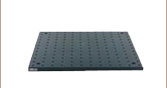
| Mounting Base | 1/4"-20 (or M6) Clearance Slots Spaced 3.0" (Compatible with Thorlabs Breadboards) |
| General Controller Specifications | |
| Frequency Resolution | 0.01 Hz (MC1F2 & MC1F2P10 Blades) 0.1 Hz (MC1F10HP Blade) 1 Hz (All Other Blades) |
| Chopping Range |
Harmonic: 2 to 15x Sub-Harmonic: 1/2 to 1/15x |
| Frequency Drift | <20 ppm/°C |
| Input and Output Connectors | BNC |
| Display Type | 240 x 124 Pixel LCD |
| Menu Control | Twist / Push-Button Knob |
| Input Power Connectiona | IEC Connector |
| Operating Temperature | 10 – 40 °C |
| Dimensions (W x H x D) | 6.05" x 2.88" x 11.54" (153.6 mm x 73.2 mm x 293.1 mm) |
| Weight | 5 lbs (2.3 kg) |
| Shipped Weight | 9.1 lbs (4.1 kg) |
| Power Supply | |
| Supply Type | Linear |
| Voltage Selection | 115 / 230 VAC Switchable |
| Input Voltage | 100/115 VAC ± 10%, 230 VAC ± 10% |
| Line Frequency | 50 – 60 Hz |
| Input Power | 20 VA Max |
| Fuse Ratings | 250 mA @ 115 VAC, 125 mA @ 230 VAC |
| Fuse Type | IEC60127-2/III (250 V, Slo-blo Type ‘T’) |
| Fuse Size | 5 x 20 mm |
| Input/Output Specifications | |
|---|---|
| Ext. Input Compatibility | TTL/CMOS |
| Ext. Input Voltage Rangea | 0 – 5 V |
| Input High | >2 V |
| Input Low | <0.8 V |
| Ext. Input Impedance | 200 Ω |
| Ref Out Compatibility | TTL/CMOS |
| Ref Out Voltage Rangea | 0 – 5 V Typical |
| Ref Out Impedance | 200 Ω |
| Min Load Impedanceb | 500 Ω |
| Ref Out Signals | Inner/Outer Slot Chopping Blade, Synthesizer, Sum & Diff Frequencies |
| Ref Out Selection | Selectable Menu or USB command ‘O’ |
| Communications | |
| Communications Port | USB |
| Protocol | USB (RS232 Emulated) |
| Baud Rate | 115,200 (fixed) |
| Data Bits | 8 |
| Stop Bits | 1 |
| Parity | None |
| Handshaking | None |
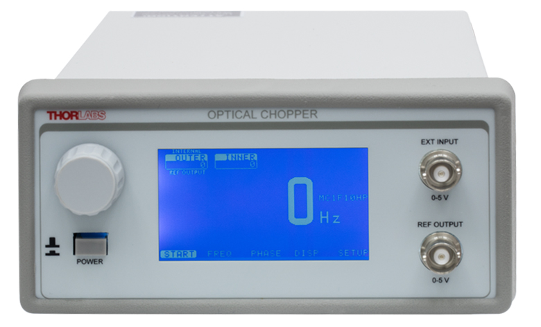
Click to Enlarge
Figure 3.1 Controller Front Panel
The front panel of the MC2000B offers two female BNC ports, one for an external input and one for the reference output. Pin diagrams for both ports are shown below.
Click to Enlarge
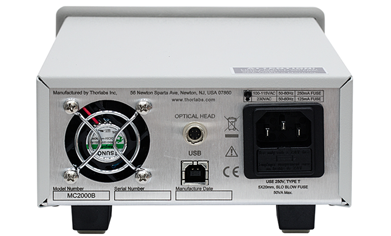
Figure 3.2 Controller Back Panel
The back panel of the MC2000B offers a USB 2.0 Type B port and an Optical Head port featuring a H

Click to Enlarge
Figure 3.3 Chopper Head Back Panel
The chopper head back panel offers an
External Input
BNC Female
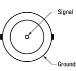
TTL/CMOS, 200 Ω Input Impedance, 0 - 5 V Input Range
Reference Output
BNC Female
TTL/CMOS, 200 Ω Output Impedance, 0 - 5 V Input Range, 500 Ω Min Load Impedance
Computer Connection
USB Type B

USB 2.0 Type A to B Cable
Interface Connector
HR10A-7R-6P
| Pin | Description | Pin | Description |
|---|---|---|---|
| 1 | Motor + | 4 | Feedback Sensor |
| 2 | Motor - | 5 | Phase Sensor |
| 3 | VCC | 6 | Ground |
Operation
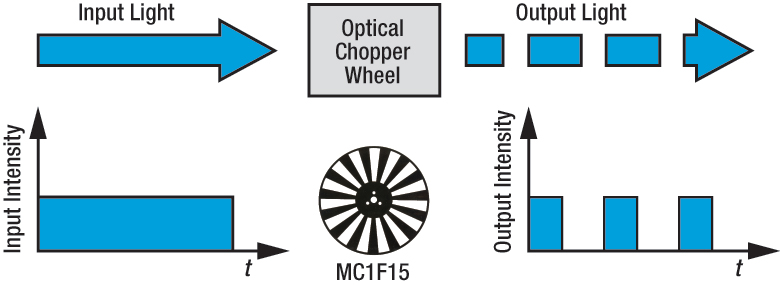
An optical chopper is an electromechanical instrument that periodically interrupts a beam of light. The MC2000B Optical Chopper is a rotary type composed of a benchtop controller, motor head assembly, and slotted chopper blade/wheel.
Applications
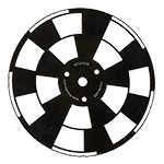
Figure 4.1 MC2F57B Dual Frequency Blade
Unlike conventional, open-loop speed control designs, the PLL speed control circuit also allows the MC2000B chopper to be synchronized to external reference signals, including other MC2000B choppers and reference sources such as DSP lock-in amplifiers.
For more advanced measurements, the MC2000B can lock to a harmonic, sub-harmonic, or fractional-harmonic of an external reference frequency. The on-board microprocessor is used to multiply the external reference up to the 15th harmonic or to divide the reference down to the 15th sub-harmonic. By combining both the frequency multiplication and division together, a fractional harmonic can be obtained.
In order to maximize the slope of the signal as the blade rotates (i.e., minimize the time to fully open or closed), the beam should be focused onto the widest portion of the slot in the chopper blade.
The MC2000B also supports 2-frequency chopping from a single chopper blade (example MC2F57B blade shown in Figure 4.1). We offer five different dual frequency blades (see below or refer to the Specs tab for details). The combination of dual frequency slots on one blade allows a single beam to be split and individually modulated for ratiometric experiments. Another example application is a pump-probe experiment where the pump beam is modulated at the outer frequency while modulating a probe beam at the inner frequency. The MC2000B provides the sum and difference frequencies of each dual frequency blade for accurate lock-in detection of the frequency-mixed response.
Click to Enlarge
Figure 5.1 MC2000B Software Screenshot
Software with GUI for Remote Operation of the MC2000B Chopper Controller
Software
Version 2.1.0
Software package to control the MC2000B. The installer includes the necessary drivers. This software package is compatible with the lastest firmware for the system and supports writing programs to control the MC2000B using C++ or LabVIEW.

Insights into Beam Characterization
Scroll down to read about:
- Beam Size Measurement Using a Chopper Wheel
Click here for more insights into lab practices and equipment.
Beam Size Measurement Using a Chopper Wheel
Click to Enlarge
Figure 191B The blade traces an arc length of Rθ through the center of the beam and has an angular rotation rate of  f. The chopper wheel shown is MC1F2.
Click to Enlarge
Figure 191A An approximate measurement of beam size can be found using the illustrated setup. As the blade of the chopper wheel passes through the beam, an S-curve is traced out on the oscilloscope.
Click to Enlarge
Figure 191D The diameter of a Gaussian beam is often given in terms of the 1/e2 full width.

Click to Enlarge
Figure 191C Rise time (tr ) of the intensity signal is typically measured between the 10% and 90% points on the curve. The rise time depends on the wheel's rotation rate and the beam diameter.
Camera and scanning-slit beam profilers are tools for characterizing beam size and shape, but these instruments cannot provide an accurate measurement if the beam size is too small or the wavelength is outside of the operating range.
A chopper wheel, photodetector, and oscilloscope can provide an approximate measurement of the beam size (Figure 191A). As the rotating chopper wheel's blade passes through the beam, an S-shaped trace is displayed on the oscilloscope.
When the blade sweeps through the angle θ , the rise or fall time of the S-curve is proportional to the size of the beam along the direction of the blade's travel (Figure 191B). A point on the blade located a distance R from the center of the wheel sweeps through an arc length (Rθ ) that is approximately equal to the size of the beam along this direction.
To make this beam size measurement, the combined response of the detector and oscilloscope should be much faster than the signal's rate of change.
Example: S-Curve with Rising Edge
The angle ftr )ftr )

includes a factor of 1.56, which accounts for the portion of the beam measured between the 10% and 90% intensity points being smaller than the 1/e2 beam diameter.
Date of Last Edit: June 22, 2021
Content improved by our readers!
| Posted Comments: | |
Ben Sukup
(posted 2025-12-12 09:34:05.35) My chopping wheels came shipped in a UNLINE padded envelope, the padding was made out of shredded paper. No way to get the envelopes open without causing a huge amount of dust to be released from the padding. Made a big mess. user
(posted 2025-11-18 15:02:04.33) Hello, is it possible to buy only the cable that connects the chopper controller (MC2000B) to the head? We misplaced the one that was included with the system. ksosnowski
(posted 2025-11-18 12:54:50.0) Hello, and thanks for reaching out to us. Yes we can provide quotes for spare components like the chopper cable or chopper head upon request as a special item. You can email us directly at techsupport@thorlabs.com for such requests so we can ensure the proper component is quoted for your system. I have reached out directly to discuss this further. Pang Wang
(posted 2024-10-29 13:29:56.507) Hi, we plan to use this chopper in a glovebox. To do this, we’ll need to transfer the chopper head through the gate by cycling vacuum and refilling with N₂ three times. Can the chopper head withstand brief exposure to a vacuum? ksosnowski
(posted 2024-11-04 04:55:42.0) Hello Pang, thanks for reaching out to us. The chopper head's anodized metal body, epoxies, and cable all could potentially outgas which can prevent some vacuum systems from pumping down or potentially contaminate other devices through redepositing outgassed material. However while we have not tested this, we do not expect any chopper performance issues from exposure to vacuum. I have contacted you directly to further discuss this application. Arne Held
(posted 2024-09-30 14:44:07.53) Hi,
we do have the MC2000. Is it possible, that the PLL slowly drifts such that the phase between reference freq and chopper freq changes over the time (hours)?
Best regards
Arne jpolaris
(posted 2024-10-02 07:26:38.0) Thank you for contacting Thorlabs. Issues with locking can arise if the incorrect blade settings are chosen, as there is a set of PID parameters specific to each blade. It would be a good idea to make sure you have selected the correct blade, and that no modifications have been made to the blade itself. Sometimes a dirty photodiode in the chopper head can cause issues with locking. It might be worth gently cleaning with canned air. That being said, the circuitry monitoring the chop activity is fast enough that a chopped pulse should never be missed. If phase was accumulating over time, you could expect the motor to speed up to minimize such an error. I have reached out to you directly to discuss further. zhu junan
(posted 2024-08-18 02:45:41.347) I want to ask the screw type of chopper head to fix the Blades
我想了解斩波片固定螺丝的尺寸以及是否能购买相应螺丝 user
(posted 2024-03-02 21:37:29.123) Dear sir/madam, when I using MC2000B-EC and MCEF10A blade cut a continue laser to 20Hz pulse laser, if I chose "Target reference-out signal", is there a 20Hz pulse electrical signal output from the reference-out port? And if I chose phase at 0 degree, whether the pulse electrical signal has the same phase with pulse laser? If I chose phase at 180 degrees, whether the laser has the opposite phase to the pulse laser? cdolbashian
(posted 2024-03-18 11:42:53.0) Thank you for reaching out to us with this inquiry. The phase is measured with respect to the optical sensor toward the 6-o'clock position on the chopper head. The electrical signal is a nominal waveform. As a result they are not necessarily in phase with each other. By adjusting the relative phase of the chopper, you can change the phase such that the transmitted beam's phase matches the reference frequency of the chopper. Low Yi Qin
(posted 2024-01-22 17:52:41.693) Hi sir / madam,
May I check if the following chopper system can allow reducing the x-ray beam to generate a pulsed beam from a continuous one? If not, if you can help in supporting the acquirement of such equipment? ksosnowski
(posted 2024-01-22 12:45:47.0) Thanks for reaching out to Thorlabs. Our current blades for the MC2000B system are all made of 1095 blue spring steel, which may not block x-rays well. Unfortunately, we are not currently able to provide lead blades or thicker blades for this. Changing the mass will also change the moment of inertia of the blade, which can negatively effect the stability and jitter of the system. Our firmware has a fixed profile which we've designed for each blade and does not include a method for changing the PID coefficients. I have reached out directly to discuss this application in further detail. Bernd Kaifler
(posted 2023-12-19 02:17:06.45) I have made a custom blade which is similar to the blade MC1F2P10 but has a larger moment of inerta. Obviously the PID parameters are not optimal for the new blade and the phase jitter is quite large. Is there any way to adjust the PID parameters (mabye via a special command)? ksosnowski
(posted 2023-12-19 12:04:52.0) Hello Bernd, thanks for reaching out to Thorlabs. Yes the increased jitter is sadly to be expected with a larger moment of inertia and it would require a special PID to perform better. The profiles are a fixed part of the MC2000B firmware and we do not currently provide any custom firmware to edit profiles. Extensive design and testing went into establishing the existing blade profiles to meet the strict system jitter requirements. I have reached out directly to discuss this application further. Sandip Kundu
(posted 2023-11-21 23:30:06.263) Hi,
Is it possible to chop a laser beam in a non periodic interval using this chopper which has the blade in periodic manner? If yes, please confirm the following details.
(i) Response time( time to start the rotation after giving the signal)
(ii) Is it possible to rotate the blades forward and backward both ? ksosnowski
(posted 2023-11-22 02:24:49.0) Hello Sandip, thanks for reaching out to Thorlabs. Our choppers are not meant to have a quick-start like this. It can take a few seconds for the blade to reach full speed depending on the blade used and speed required. Each blade has its own internal PID settings that are used to maintain stable phase and low jitter. While we do not have an exact timing from startup to locking, I do not think the chopper would be particularly effective in this setup. The chopper head is designed to run in a single direction only due to the motor used and the controller in MC2000B. Annie M
(posted 2023-10-25 00:10:24.193) Hi, We have a fs laser which emits pulses at 1KHz repetition rate. We are looking for a chopper which can be used to synchronize to the pulses and run it at 100Hz. Will MC2000 do that job? ksosnowski
(posted 2023-11-01 10:59:38.0) Hello Annie, thanks for reaching out to Thorlabs. This repetition rate and frequency range is fine for use with our current MC2000B and previous MC2000 as long as the blade chosen covers this frequency as well. The harmonic multiplier function can be used for up to 15x or 1/15x multiplication of the applied frequency, while remaining in the blade's operating range. We have not tested the damage threshold of the chopper blades however and it is difficult to say whether it will work with every ultrafast laser. I would recommend testing one of our spare blades for laser exposure in your current setup to see if your wavelength, beam size, beam profile, rep rate, and pulse energy result in burn-through. João Ricarte
(posted 2023-09-27 09:35:31.33) Dear technical team,
I would want to know if this chopper can operate with CO2 laser light (laser lines 11.5 um and 9.3 um) and whcih is the damage threshold for these wavelenght.
Thank you! ksosnowski
(posted 2023-09-27 04:31:21.0) Hello João, thanks for reaching out to Thorlabs. We have not tested the damage threshold on these chopper blades however some main concerns are beam size/power density, and managing scattering off the blades. The threshold would also be dependent on factors like whether and how quickly the blade is spinning under the beam. The blades are made from 1095 blue spring steel, with a black oxide sealer finish. The chopper is not intended as a high power beam dump however we do sell individual blades if you are interested in testing some in your setup. user
(posted 2023-09-11 14:00:15.443) Dears,
It could be possible to obtain a custom blade for 500 Hz operation and beam diameter of >16 mm? ksosnowski
(posted 2023-09-18 05:33:37.0) Hello, thanks for reaching out to Thorlabs. For each of the blades we offer we have developed specific profiles in our firmware to achieve the performance specifications listed. Due to firmware design, there is not a way to edit the existing blade profiles. We have been able to provide some custom blades however the new blade needs to mimic the operation of an existing blade for the chopper system and we are unable to guarantee performance in these cases. Especially changing the mass of the blade can change the moment of inertia and effect the controller's PID stability resulting in increased phase error. This would require user experimentation in setup. I have reached out directly to discuss this application further. Eberhard Riedle
(posted 2023-07-10 10:33:02.473) Please specify which minimum duration the TTL external input signal (reference) for the MC2000B has to have. cdolbashian
(posted 2023-07-21 11:41:30.0) Thank you for reaching out to us with this inquiry! I was able to test this myself down to a 150ns pulses with a 1KHz rep rate. While doing this, I was able to see our specced jitter performance even with such a low duty cycle. user
(posted 2023-07-04 11:29:39.707) I've lost small Phillips Pan Head Screws for this MC1F15. Can I get or buy new screws? ksosnowski
(posted 2023-07-05 04:30:08.0) Thanks for reaching out to Thorlabs. We do not offer this component separately on our site however I have reached out directly to further assist with a quote for this. For any component like this we recommend to contact techsupport@thorlabs.com directly. hmm... interesting!
(posted 2023-06-19 09:08:00.127) Is there a way to integrate the chopper head with a cage system (30 or 60 mm) such that the wheel is supported by the cage rods? This application will be free-standing and will not have an optical breadboard underneath. I understand that the chopper head is a bit heavy and vibrating and I'd have to find a way to manage those issues. ksosnowski
(posted 2023-07-07 04:55:32.0) Thanks for reaching out to Thorlabs. Unfortunately, we do not have any mounts to directly attach the chopper head into a standalone cage system. On our page with CBB1 we do show an example of using the U-bench to provide a rigid cage route around the chopper head, however in this scenario both the cage system and chopper head would still be supported from underneath. The weight and vibrations would definitely need to be addressed, and sadly this is not something we have a solution for currently. Our various shutter products are perhaps better suited for mounting in-line with the cage or optics tubes as well, however the frequency range and timing specs are much different on the shutters. I have reached out directly to discuss your application in further detail. AS_ Thomas
(posted 2023-05-03 16:09:03.527) What is the upper limit of the external trigger (in kHz) to MC2000B, chopper head with MC1F10HP blade. Thanks ksosnowski
(posted 2023-05-03 09:23:40.0) Thanks for reaching out to Thorlabs. The upper frequency limit with the MC2000B system is 10kHz. Each blade has its own frequency limit for operation as well and the MC1F10HP outer slots can chop 200Hz-10kHz. The Harmonic functions mentioned on manual page 12 can be used to multiply an external frequency from 15x to 1/15x into range for the blade used, however as the controller is not stable beyond 10kHz, the reference and harmonic frequencies must be within this range to be properly locked to. user
(posted 2023-01-11 10:37:44.19) I am trying to run a MC1F10 chopper blade with a MC 2000 controller on 50 Hz. Unfortunately, the chopper blade wobbles. I already tried using another chopper wheel and chopper head, but can not get it running stable on such low frequencies. Is there any way to make the chopper blade stop wobbling? ksosnowski
(posted 2023-01-13 03:28:15.0) Thanks for reaching out to Thorlabs. This blade can operate as low as 20Hz with our MC2000 and MC2000B controllers. The manual's Maintenance section has details on how to carefully clean the blade and sensor, so that debris doesn't interfere with the chopper feedback. If the correct blade profile isn't selected, this will load different PID values to the feedback loop, and can cause "wobbling" or oscillations around the set frequency. Damaged, altered, or poorly-secured blades could also have different mechanical properties than the feedback accounts for, leading to increased jitter. I have reached out directly to discuss this issue in further detail. user
(posted 2022-04-25 09:00:17.42) I am chopping a laser with a remote MC2000B using computer commands. Sometimes I want to stop the chopper and have a cw beam, but once the power is cut the blade spins down at random. Is there a command to make sure the blade "stops open" and the beam will be allowed to pass? cdolbashian
(posted 2022-05-04 04:47:23.0) Thank you for reaching out to us Matthew. Unfortunately, due to the unidirectional motion of the motor in this device, without modification, you would not be able to stop the blade a specific position. Perhaps you can us some motorized turning mirrors to redirect your beam around your chopper rather than requiring an open slot. I have reached out to you directly to discuss your application. cdolbashian
(posted 2022-05-04 04:47:23.0) Thank you for reaching out to us Matthew. Unfortunately, due to the unidirectional motion of the motor in this device, without modification, you would not be able to stop the blade a specific position. Perhaps you can us some motorized turning mirrors to redirect your beam around your chopper rather than requiring an open slot. I have reached out to you directly to discuss your application. user
(posted 2022-04-16 19:24:52.43) Is it possible to convert a 2000B-EC to a 2000B without sending it back to Thorlabs? cdolbashian
(posted 2022-05-04 04:38:34.0) Thank you for reaching out to us with this inquiry. Switching between these two modes is fairly straightforward. The process requires swapping a fuse and adjusting a switch on the main circuitboard inside of the device. Since there was no contact email left, please feel free to email us at techsupport@thorlabs.com, so we can share the process with you directly. Sanah B
(posted 2022-04-15 16:28:34.017) I'm trying to use the python package for this controller software but am unable to load the command library from MC2000CommandLibWin32.dll. The problem fails when I try to register the .dll file on my windows computer using the regsvr32 command. The error says: "The module MC2000CommandLibWin32.dll was loaded but the entry-point DllRegisterServer was not found. Make sure that MC2000CommandLibWin32.dll is a valid DLL or OCS file and then try again."
How do I fix this problem so that I'm able to load the command library in python? cdolbashian
(posted 2022-04-20 04:43:45.0) Thank you for reaching out to us with this inquiry Sanah. We have contacted you directly to troubleshoot the software-related issues you seem to be having. Craig Prater
(posted 2022-02-09 15:23:11.967) Hi. I have a suggestion regarding the chopper. I am finding that the chopper motor introduces an unacceptable amount of vibration into my optical table. It would be great if you offered a shock mounting kit for the chopper to provide some vibration isolation. I see you sell sorbothane sheets, so it could be as easy as die cutting some pieces that are fit to the mounting base size.
Thanks,
Craig cdolbashian
(posted 2022-02-10 12:02:09.0) Thank you for reaching out to us with this request Craig! We take feedback like this very graciously, and we thank you for the opportunity to improve our product! I have passed this feedback along to our development team for potential future product releases. Benjamin Gerard
(posted 2022-01-28 18:22:29.78) Hi. We are finding that the current phase jitter is a limitation to our experiments. Operating at around 100 Hz we measuring the phase jitter at the level of 0.25 deg rms (actually 2.5x lower than the spec for this MC2F47 blade in your manual here on page 25: https://www.thorlabs.com/drawings/a903fc7e741759f7-21995EA9-0C7D-F4A6-48E8B3B75815532E/MC2000B-EC-Manual.pdf). Do you have possible solutions to improve this jitter (e.g., better motor control and/or uniformity of the fabricated blades) by at least up to 10x? If so I would be interested in chatting further. Thanks! ksosnowski
(posted 2022-02-21 10:55:46.0) Thank you for reaching out to us Benjamin. While we do offer some wheels like MC1F10HP with higher performance than MC2F47, currently our products are at the limits of the motor performance and tolerance of the blade manufacturing and we do not have any options for <0.025 deg RMS jitter. The jitter specs can be found on page 25 of the manual. Craig Prater
(posted 2022-01-28 15:41:57.347) Can you please provide a 64 bit compatible LabVIEW SDK for this product? I have not used 32 bit LabVIEW for many years and all my other apps use 64 bit. cdolbashian
(posted 2022-01-31 05:29:31.0) Thank you for reaching out to us Craig. The DLL of interest, "MC2000CommandLibWin64.dll” should be installed on your machine with the software installation, and it should be installed to the folder ”C:\Program Files (x86)\Thorlabs\MC2000B\Sample\Thorlabs_MC2000B_LabVIEWSDK\Thorlabs_MC2000B\Library”. user
(posted 2021-11-08 17:59:00.76) Dear Madam/Sir, I wonder whether the chopper system include the cable which connects the chopper head to the MC2000B controller. If not, where can I find it? Thanks in advance! cdolbashian
(posted 2021-11-08 01:28:59.0) Thank you for reaching out to us with this inquiry. We include the cable which connects from the chopper to the control box as well as a USB cable for remote control of the device via serial commands. Subramanyan Varanakkottu
(posted 2021-08-23 14:46:23.597) Dear Madam/Sir,
We are looking for a light modulator which can work upto 20KHz. The device can be mechanical/electro-optic/AOM, but with a good modulation depth. Kindly suggest.
Thanking you in advance,
Subramanyan YLohia
(posted 2021-08-23 03:52:51.0) Thank you for contacting Thorlabs. Depending on the wavelength of your source, you may find a suitable modulator on this page: https://www.thorlabs.com/newgrouppage9.cfm?objectgroup_id=2729. Michael von Arb
(posted 2021-07-12 08:16:08.887) Dear Sir or Madam
On the product website of the Optical Chopper System and Chopper Wheels under "Insights" (https://www.thorlabs.com/newgrouppage9.cfm?objectgroup_id=287) you specify the factor 0.64 for the calculation of the diameter of the beam. On the other hand on the Insights website (https://www.thorlabs.com/newgrouppage9.cfm?objectgroup_id=14181) you specify a factor of 1.56. Which is the correct factor? Is it possible that you have changed the factor recently? Can you explain this difference.
Thank you in advance for your answer.
Best
Michael von Arb cdolbashian
(posted 2021-07-20 01:19:09.0) Than you for reaching out to us regarding this discrepency. This error was recently brought to our attention in the context of our Insight article: "Beam Size Measurement Using a Chopper Wheel". We subsequently corrected the value from .64 to 1/.64 (~1.56) on that page but seemed to miss the corresponding article on the chopper page. We have corrected the error that you found and have updated both pages to have identical, and correct, information. I have reached out to you via email to discuss any other concerns you may have. Yangting Fu
(posted 2021-07-09 05:29:28.517) Hi. I have an MC2000 optical chooper and I want to adjust the rotating speed without putting on a blade. Apparently without the blade, the rotating speed cannot be adjusted. I know there's an IR photon sensor to detect the blade speed and send it back to the controller via the feedback sensor. I am wondering if there is a way to bypass or cheat the blade speed sensing at the optical head, in order to adjust the motor rotating speed by the controller (or an external reference signal from a signal generator). Look forward to hearing from you! Thank you! cdolbashian
(posted 2021-08-02 03:03:07.0) Thank you for reaching out to us at Thorlabs. Unfortunately, without the feedback sensor, the chopper will only be able to rotate at a singular speed, with no option for adjustment. Brian Saam
(posted 2021-03-26 23:11:07.46) I have an application that would benefit from a duty cycle greater than 50% (say 80-90%). I notice that such wheels never seem to be available. Is there a reason for this? I suppose one could take a 50% wheel and remove some number of spokes to increase the duty cycle. This seems a bit crude and brute-force-ish. Am I missing something? asundararaj
(posted 2021-04-01 09:55:55.0) Thank you for contacting Thorlabs. We offer a selection of chopper blades based on common applications. If you need a custom chopper with a custom duty cycle, we have in the past offered custom blades as per user design. I have contacted you directly to discuss this further. Anthony Fortin
(posted 2021-02-10 02:51:58.853) Dear Sir or Madam,
We are now using this blade in a setup with a wavelength range of 900-2500nm.
I have seen that the material was "blue spring steel".
Do you happen by any chance to have a reflectivity curve of such a material in that wavelength range ? Indeed we would like to investigate the sources of straylight in our setup and would like to have more knowledge regarding this blade.
Thanks in advance,
Yours sincerely,
Anthony FORTIN asundararaj
(posted 2021-04-02 02:41:17.0) Thank you for contacting Thorlabs. While, we do not have the reflectivity curve for the choppers, the Blue Spring steel material is coated in a black oxide which is done to to add mild corrosion resistance and to minimize reflectance in the visible and NIR region. Dovletgeldi Seyitliyev
(posted 2020-10-10 21:28:31.497) Hello, I have broken MC2000 controller,
How much it'll take to fix it? Do you fix? Thanks. asundararaj
(posted 2021-04-02 08:09:02.0) Thank you for contacting Thorlabs. The cost of the repairs are typically estimated after the inspection. I have directly contacted you to troubleshoot the issues you are facing and to help set up an RMA if necessary. Dovletgeldi Seyitliyev
(posted 2020-09-05 01:13:55.957) Hello,
My MC2000 chopper head failed,
Controller works fine (tested with identical head),
Can you provide/sell chopper head only? asundararaj
(posted 2020-09-08 04:25:55.0) Thank you for contacting Thorlabs. The MC2000 and the MC2000B uses identical chopper heads. We should be able to provide the chopper head alone as a component part. For future quote requests, please click the red Request Quote button or contact techsupport@thorlabs.com. I have contacted you directly via email for the quote. Kelly M
(posted 2020-03-03 08:17:47.96) Dear Thorlabs technical support,
Is there a Linux driver for the MC2000B chopper controller?
Thanks,
Kelly asundararaj
(posted 2020-03-04 08:23:26.0) Thank you for contacting Thorlabs. We do not have dedicated Linux drivers for our chopper controller and do not have any plans for supporting Linux in the foreseeable future. Tasos Koulouklidis
(posted 2020-03-03 07:26:41.55) Dear Thorlabs technical support, I use the MC2F47 blade and I try to chop at 25 Hz. Unfortunately this is not possible. If I set the frequency to numbers less than 50 Hz
the ref out signal becomes extremely unstable, the indicated frequency constantly deviates and the frequency cannot be locked. The same thing happens if I use an external reference at 50 Hz and try to get the harmonic at 25 Hz. The chopper works fine for higher frequencies though. Could you please help me with this issue?
Best regards,
Tasos asundararaj
(posted 2020-03-03 04:52:30.0) Thank you for contacting Thorlabs. I have reached out to you via email to troubleshoot this issue. Yaroslav Sych
(posted 2020-01-30 17:52:55.733) Dear Thorlabs technical support,
I would like to ask how to switch off the feedback from the chopper head (measured with the IR diode)? I have designed chopper wheels with my own geometry and need to use all the blade space.
Is there a simple way to switch it off in the software? Except for feeding external signal to drive the controller.
Kind regards,
Yaroslav asundararaj
(posted 2020-02-04 03:19:44.0) Thank you for contacting Thorlabs. The IR feedback in the MC2000B cannot be disabled in the software. The operation of the MC2000B relies on the feedback for locking into the right frequency, and so this is not something that can be disabled for normal operation. user
(posted 2019-10-26 06:14:44.017) Hello,
The included ~2m interface cable is a bit short for my appliation. Is the 10' TC200CAB10 cable compatible with the chopper, or is there any other available cable? Are there issues with changing the cable length? Thank you. asundararaj
(posted 2019-10-28 05:03:06.0) Thank you for contacting Thorlabs. The TC200CAB10 would not be compatible with the Optical Choppers, since the optical chopper requires female connectors on either ends. We typically do not recommend longer cables due to the possibility of signal delays among other issues. I have contacted you directly regarding the possibility of offering a longer cable. BANG-YU HSU
(posted 2019-08-07 22:15:32.357) Dear Thorlabs tech support, is it possible your motor/fans in MC2000B can work with SR540 chopper controller? Thank you. -Ben YLohia
(posted 2019-08-08 03:28:01.0) Hello Ben, thank you for contacting Thorlabs. Unfortunately, we cannot guarantee any level of performance of the MC2000B motor with any third party controller. Our Applications Engineers can be contacted directly by emailing techsupport@thorlabs.com. Vasyl Yatsyna
(posted 2019-04-18 10:18:15.943) Hello, I have a technical question about the chopper system and blades. How can we reach duty cycle less than 10 % if the repetition rate is only 5-10 Hz? Can two blades MC1F2P10 be combined for this purpose? We would like to use a single controller for this purpose. Thanks in advance. nbayconich
(posted 2019-04-19 10:24:44.0) Thank you for contacting Thorlabs. The duty cycle is independent of the operating frequency of the chopper blades, in order to achieve a lower duty cycle I would recommend using one of the adjustable blades such as MC1F10A. The lower operating frequency to the MC1F10A is limited to 20hz however and cannot be modified to use at a lower frequency.
We do not recommend using two blades on one chopper wheel housing, a configuration like this could not be guaranteed to be stable, stability also sets the lower operating frequency for these blades. xyzhang
(posted 2018-10-31 20:30:41.39) I bought one MC2000B several years ago and synchronized to a 10 kHz ref signal. It was working fine until recently. The ref input frequency showing on the screening is off by 9 - 20 Hz. Instead of 10000 Hz, it shows 100011 or seminar numbers. I changed to different input frequency, just for checking, still saw the same problem. Please help. YLohia
(posted 2018-12-03 10:18:12.0) Hello, thank you for contacting Thorlabs. I reached out to the email provided by you with a few questions about your setup. If you did not receive my email and the issue still persists, please contact us at techsupport@thorlabs.com. dugan
(posted 2018-07-31 11:09:11.807) I am using the MC2000B with the standard MC1F10HP chopper blade to chop a 1 kHz pulse train. Everything works fine at the 1st, 2nd, and 5th subharmonics, but I need to chop at 100 Hz. When I get to the 10th subharmonic, I suddenly cannot control the phase. The display says that I've changed the phase, and the chopper will lock again (albeit slowly), but when I look at the pulse train on a photodiode, the phase has not actually changed. Again, this problem does not occur when chopping down to 200 Hz, only at 100 Hz. YLohia
(posted 2018-09-17 09:44:40.0) Hello, thank you for contacting Thorlabs. We ran this setup under exactly the same conditions and found no issues. For further troubleshooting, we would have to bring this piece in for inspection. I have reached out to you directly to initiate the RMA process. lhagaman
(posted 2018-05-29 12:40:43.25) Hi, do you have any information of how this chopper wheel might behave in vacuum? Any concerns of overheating or estimates of the outgassing? Thank you. YLohia
(posted 2018-05-29 04:25:57.0) Hello, thank you for contacting Thorlabs. We do not recommend these units for vacuum-based applications since these contain anodized aluminum so outgassing would definitely be an issue. That being said, we have not performed any testing for this product under these conditions since that is not the intended use. user
(posted 2018-05-09 15:24:55.553) what's the material made of (the chopper wheel)?
thanks! YLohia
(posted 2018-05-10 09:28:18.0) Hello, thank you for contacting Thorlabs. These chopper wheels are made of 0.01" thick blue clock spring steel and have a black oxide finish. a.brash
(posted 2018-04-13 16:19:14.723) We have a slightly older MC2000 controller unit, is there any way that this could be made compatible with the MC1F10A variable duty cycle blade? YLohia
(posted 2018-04-13 01:53:28.0) Hello, thank you for contacting Thorlabs. Please see footnote d on the main product family page for the blades. Unfortunately, this blade is not backwards compatible with the old MC2000 unit. marco.cammarata
(posted 2018-03-30 16:45:54.56) Hi,
I have a kHz beam that I want to chop down to ~100Hz.
Unfortunately I do not think MC1F2P10 is an option because if I am not mistaken one needs to provide a reference signal higher that the chopper frequency thus creating a phase uncertainty.
Am I right ?
The other option: MC1F6P10 can be used with beams smaller than the ~6mm I will be using.
Thanks,
marco YLohia
(posted 2018-04-04 12:12:22.0) Hello Marco, thank you for contacting Thorlabs. The MC1F2P10 provides a very stable low frequency chopping of up to 200 Hz. The optical chopper head uses the outer frequency (outer blades) as a reference signal to lock the blade to the frequency generator. Since these outer slots "chop" at a higher frequency, the jitter and phase uncertainty are actually minimized. In addition, this chopper can employ a dual photo-interrupter arrangement to track the phase of the inner slot. sgreen
(posted 2017-11-21 14:56:22.31) Can I get documentation for this chopper? Including datasheets, manuals, etc, etc.
We are researching choppers and are interested in this one, but need to make sure it's exactly what we need.
Any help you can provide would be greatly appreciated. nbayconich
(posted 2017-12-28 02:36:18.0) Thank you for contacting Thorlabs. The complete operating manual for the MC2000B chopper system can be downloaded directly from our website under the Document icon. The link below will direct you to the operating manual.
https://www.thorlabs.com/_sd.cfm?fileName=TTN102010-D02.pdf&partNumber=MC2000B
Additional specifications can be found on our webpage regarding the chopping blade specifications & controller specifications. I will reach out to you directly to discuss your application requirements for this chopper system user
(posted 2016-12-15 17:40:05.81) Do any of these blades fit the SR540 chopper from Stanford Research Systems? tfrisch
(posted 2016-12-20 10:00:34.0) Hello, thank you for contacting Thorlabs. While we don't have any testing using SR540, I notice that the two systems use a different reference slots, so I would not expect them to be compatible. meziani
(posted 2016-11-22 13:22:18.73) Hello Dear
We are facing a problem with optical chopper MC2000 where some times is locked at 254.2 Hz. If we fix the frequency at 333 Hz, then after a while (1 or 2 hours) goes back to this frequency and remain locked. We need then to restart the chopper and begin again. We do not know if it's from the motor or from the control. Did you face something similar? do you know how we can fix it?
Best regards tfrisch
(posted 2016-11-30 08:34:42.0) Hello, thank you for contacting Thorlabs. I will reach out to you about trouble shooting for the chopper. mjeong3
(posted 2016-08-10 05:13:13.153) Would it be possible for me to take the blade off to replace it with a different component? I'm wondering what that small thing on the bottom of the mount is. Is that component an absolute necessitiy when it comes to spinning the chopper? jlow
(posted 2016-08-10 11:53:26.0) Response from Jeremy at Thorlabs: You can take off the chopper blade and replace it with one of our other chopper blades for different frequency ranges. The small component at the base of the chopper head is the opto-interrupter, which is used by the controller as feedback to actively measure the actual chopping frequency and make adjustment to the motor speed based on the set chopping frequency. It is necessary for the operation of the optical chopper. ghjkl0822
(posted 2016-01-11 17:03:02.46) it's going to slow when chopper frequency below 3hz //
we use 2slot mc1f2
mc2000-ec
frequency 20hz over it's very good work. besembeson
(posted 2016-01-12 06:11:39.0) Response from Bweh at Thorlabs USA: I will contact you to get a better understanding of your application and what deviation you see from the expected performance at 3Hz. m.peccianti
(posted 2015-12-17 14:56:18.85) We are performing a synchronized lock in detection
chopping a 1KHz pulsed sources at 500Hz (On - Off modulation).
The chopper is set to target 1/2 of the sync frequency of the laser. However
if we compare the target output (not the actual) with the 1KHz sync we can clearly see a time jitter within 10-20us scale and with a period within the 0.1-0.2s.
This shift create a significant artifact on the lock-in read which is suppose to discriminate a 500Hz phenomenon on a 1KHz carrier. The lock in should be immune to the 1KHZ as it will be coherently averaged out. Instead the jitter appear as an artifact in the reading.
It seems that the target is generated from the PLL (and not from a digital division) and the correction coefficient allows for the given fluctuation.
We never noticed the problem before, is there a chance our unit is faulty? (but it is also possible we mistaken the effect with other noise sources)
Best besembeson
(posted 2015-12-21 05:46:23.0) Response from Bweh at Thorlabs USA: This seems to be a complex issue, but I suspect phase jitter is coming into play. For us to evaluate this further, we would need to know which optical chopper wheel you use for your application. Since you are located in the UK, I will have our UK Technical Support team follow-up with you. On a related side note, we are also in the process of updating the MC2000 firmware with some fairly significant performance upgrades to stability and locking. stefan.ringleb
(posted 2015-09-02 12:06:46.72) I just tested the MC-2000 with 2 MC1F2 Blades rotated by 120° to each other. So I got a duty cycle of 1/6 for the copped light. I also could change the phase easily in respect to an input signal. So this works very good. Unfortunately the reference output signal does not have this duty cycle but 1/1. Is it possible to fix this? joachim.kaiser
(posted 2015-05-07 15:52:55.69) The reference signal of the MC2000 seems to be captured by an optical light barrier watching the blades. Is there the possibility to switch off/disable the light barriers LED by SW to avoid illumination from the LED? jlow
(posted 2015-05-07 01:55:27.0) Response from Jeremy at Thorlabs: The LED inside the opto-interrupter is needed for the feedback to determine the actual chopping frequency. We might be able to circumvent this somehow in your setup another way. I will contact you directly about this. kedves
(posted 2014-09-30 19:16:01.433) Dear Thorlabs, is it possible to use two blades with some phase difference in order to change the open/closed ratio from 1/1 to e.g. 1/9, i.e. to transmit only every 10th pulse from a sequence of 1 kHz? Is your model MC2000 with two MC1F2 blades capable of doing this? It should run at 100 Hz chopping frequency and block the beam 90% of the time. The laser is a femtosecond Ti:sapphire laser with approx. beam diameter of 10 mm. The laser provides a synchronization signal at 1 kHz. Thanks. cdaly
(posted 2014-10-11 04:40:14.0) Response from Chris at Thorlabs: Yes, it should be possible to vary the duty cycle by using multiple blades. The phase can be controlled and locked relative to an input reference signal. Since the chopper controller can also output a reference signal, one controller can be used as the reference for the second in order to accomplish this. rajeevkini
(posted 2014-08-20 14:48:48.49) We have a femtosecond laser which emits pulses at 1KHz repetition rate. I am looking for a chopper which can be used to block each alternate pulse. Will MC2000 do that job? Will it be possible to synchronize the chopper to the pulses & run it at 500Hz so that every alternate pulse is blocked. The laser does give a reference signal at 1KHz. jlow
(posted 2014-08-21 10:02:18.0) Response from Jeremy at Thorlabs: This is possible with the MC2000. We will contact you directly to discuss more about setting this up. cdaly
(posted 2014-08-07 10:13:33.157) Response from Chris at Thorlabs: Thank you for your inquiry. Yes, we can quote this as a custom for you. I will contact you to get this started. Future custom requests can be sent directly to us at techsupport@thorlabs.com. akbariitm
(posted 2014-07-24 12:01:02.443) Can we get quotation for MC2000 with MC2F57 chopper blade? ronningent
(posted 2014-07-14 10:29:11.31) We are using a MC1000 controller with a MC1F60 blade. At startup, when we select the type of blade installed, the code "b 60" never appears. The code "b 30" appears. Selecting it allows the blade to spin. Is the output frequency still correct even though I am not able to select the correct blade? Should the MC1000 be able to select a 60 slot blade? cdaly
(posted 2014-08-07 04:09:23.0) Response from Chris at Thorlabs: The MC1000 should work with the 60 slot blade and b60 should appear as a possibility. This is likely a firmware issue. In this case however the device would need be be sent back in for the update. We will contact you directly about this. mfl
(posted 2014-06-07 14:57:57.077) Dear staff,
My name is Ming-Fu Lin from University of Illinois at Urbana-Champaign. We have MC2000 optical chopper. We would like to connect to NI Labview. do you have any specific Labview instruction/example for this device?
Thanks a lot.
Ming-Fu jlow
(posted 2014-06-11 04:19:59.0) Response from Jeremy at Thorlabs: You can do this using serial command. The is outline in Section 6 of the manual. We will contact you directly to provide more information regarding this. patrick.rymer
(posted 2014-03-10 16:11:16.123) Is it possible to buy custom chopper blades to go with this system? I need customized width of the open sections.
Thanks - PR cdaly
(posted 2014-03-11 05:42:21.0) Response from Chris at Thorlabs: Yes, we have provided custom chopper blades in the past. We will contact you directly to discuss your requirements. user
(posted 2014-02-18 10:39:32.707) I'm using the MC2000 with the MC1F100 wheel at about 9.6 kHz (external reference), this was working fine but now the motor of the chopper seems damaged (unhealthy noise when it ramps up to high speed, doesn't lock anymore, i guess the bearings of the motor have gone bad). Can i order a replacement for just the motor or chopper part from thorlabs without buying a new controller (I didn't find this on the webpages)? jlow
(posted 2014-02-25 03:59:03.0) Response from Jeremy at Thorlabs: We can take the chopper head back for evaluation and repair. Since you did not leave any contact information, can you contact our RMA department (RMA@thorlabs.com) to arrange this please? saltattam
(posted 2014-02-13 17:24:13.143) Is there a way to see the actual frequency of the disc, and not just a reference signal which may or may not be correct? If I physically stop the disc the reference signal keeps on going. Seems like I should be able to see if it's locked in or not. jlow
(posted 2014-02-14 11:00:21.0) Response from Jeremy at Thorlabs: You can see the signal from the blade by selecting "Actual" as the reference out signal. With this setting, the reference out signal is obtained from the feedback sensor reading the outer slots on a chopper wheel. hfinkenz
(posted 2014-01-08 10:47:54.44) Dear Sir/Madam,
if the motor is stopped, does the disc stop in (a) specific position(s)? We would like to run the chopper only at times during the experiment and otherwise have full transmission, without repositioning the chopper. Is there a way to achieve this automatically?
Thanks in advance! jlow
(posted 2014-01-09 04:23:39.0) Response from Jeremy at Thorlabs: The chopper does not stop at a specific position when the drive signal is removed. user
(posted 2013-08-17 19:24:53.73) Is there a way to use 20X harmonics? My external ref is 10Hz, I want the MC1F10 blade (NOT other blades) to work at 200Hz. Thank you. tcohen
(posted 2013-08-22 14:58:00.0) Response from Tim at Thorlabs: Thank you for contacting us. You can run the MC1F10 at 200Hz using the internal reference, but if using an external reference, the current edition of the MC2000 accepts harmonic values up to a maximum of 15X. esquin
(posted 2013-07-31 16:07:04.18) We are looking for a possibility to modulate the intensity of a monchromatic light source by 10% to 20%.
This modulation does not mean to turn on/off completely the light but a relatively small modulation. The reason is that the system relaxes on time and we cannot just turn off completely the light even for a small amount of time.
It is not clear to me whether a chooper system can do exactly that upon blade. Can you send me information whether this is possible?
Thank you in advance. jlow
(posted 2013-08-01 16:27:00.0) Response from Jeremy at Thorlabs: We will get in contact with you to discuss about your application and discuss the different possibility on achieving this. pseudotexan
(posted 2013-06-05 11:18:19.027) I am getting a strange problem with my chopper unit. I am using the standard 10-slot blade at 300 Hz, internally referenced. Sometimes, the blade will stop spinning, reverse direction, and then start spinning at about 260 Hz, consistently with about a 40 Hz offset for no reason. It also makes a high-pitched whine. It is unable to lock back on to the desired frequency.
Sometimes, I can temporarily solve the problem by re-seating the cable to the blade housing, but it just resets a bit later. jlow
(posted 2013-06-06 14:29:00.0) Response from Jeremy at Thorlabs: We will get in contact with you directly on troubleshooting this and possibly sending this back for evaluation. marco.cammarata
(posted 2013-04-24 04:14:55.51) Do you have any idea about the damage threshold for the MC* blades for nanosecond pulses ?
I would like to send a ~1W beam (few mm^2 area) on the wheel but - of course - I don't want to damage it. Thanks,
marco tcohen
(posted 2013-04-25 16:27:00.0) Response from Tim at Thorlabs to Marco: The chopper blades are blued clock spring steel nominally .010” thick. The blade itself is not meant for high power applications but we have not tested the damage threshold with ns pulses. dursch
(posted 2013-02-06 13:49:02.57) Our MC200 seems to run uncontrollable, meaning the chopper is always on. I have tried updating the firmware to the newest version, but that didn't help. Any suggestions on how to remedy this problem. jlow
(posted 2013-02-06 16:41:00.0) Response from Jeremy at Thorlabs: We will contact you directly to troubleshoot this issue. orich
(posted 2013-01-27 12:06:59.47) Do you have chopper blades with duty factor smaller than 0.5. This is very useful for average smaller light intensity but with high quasi CW light intensity. tcohen
(posted 2012-09-24 09:17:00.0) Response from Tim at Thorlabs: Thank you for pointing this out! While we are fixing this please reference the following values: MC1F2 = 0; MC1F6 = 1; MC1F10 = 2; MC1F15 = 3; MC1F30 = 4; MC1F60 = 5; MC1F100 = 6; MC2F57 = 7 martin.fertl
(posted 2012-09-21 07:38:36.0) To whom it may concern,
in section 6.3 of the manual the command "blade=n".
The number n is said to be found in section 6.5.2.
But neither in the printed nor in the pdf version of the manual this section exists. Can you please add this information to the manual.
Thank you very much jlow
(posted 2012-08-27 17:12:00.0) Response from Jeremy at Thorlabs: The maximum frequency for the REF IN is 10kHz. schoeps
(posted 2012-08-27 12:58:41.0) What maximum frequency is allowed as ref-in? Will I be able to use my 30kHz signal? tcohen
(posted 2012-07-19 15:29:00.0) Response from Tim at Thorlabs: Thank you for contacting us. The new blade was introduced around 12/2011. Devices with firmware <= 3.10 should be updated to the latest firmware to make use of phase control on the 2-slot blade. There were many improvements with this firmware update including reduced jitter to most blades. However, please note that the previous blade design is incompatible with >=3.11 firmware. To determine your edition of hardware and firmware, you can attempt to update the firmware as indicated on the “Software Downloads” tab. To determine your blade edition, you can check for the outer rim which is a characteristic of the new design. I will contact you directly to continue this conversation, but we will also make this information more visible on the web. jcanseco
(posted 2012-07-19 16:54:29.0) In your catalog, I saw that the MC1F2 blade was updated as follows:
"Please note the MC1F2 two-slot blade has been updated to a newer version. This new blade is only compatible with units that have firmware version 3.11 and later. For all older firmware versions, the old-style blade must be used. This blade is not backwards compatible.
"
When was this update made? What is the better properties of this new wheel? Better phase-locking or phase stability? If I purchased a MC1F2 in 2009, is it an old-style blade?
I am having a problem with the phase stability with MC1F2, while one of my colleagues does not with the same setup. I guess he bought it in 2010 or 2011. Could it be due to the update of the blade? tcohen
(posted 2012-07-05 14:12:00.0) Response from Tim at Thorlabs to Vasili: Thank you for contacting us! Devices with the 1.0 series of firmware must have a free hardware upgrade in order to use the new firmware. The firmware upgrader on the web will be replaced with a newer version soon. If there is any hardware incompatibility, this new version will provide this information along with instructions for inquiring about our free hardware upgrade. vasili.savitski
(posted 2012-07-04 16:10:33.0) Dear Sir/Madam,
We have recently purchased an MC1F100 blade to use it with our MC2000 chopper driver. Unfortunately it’s appeared that there is no such blade in the menu of the driver. We tried to update the software of MC2000 to newer version available at your web site (3.11), but update failed: ”hardware allows you to update only to version 1.05”. But we were not able to update even to this 1.05 version. So, could you please help us with this issue and explain how to use the blade MC1F100 with MC2000? We haven’t been informed on your web site that this blade can only be used only with the certain version of the software and therefore believe that this issue should be solved by you.
Best regards,
Vasili. bdada
(posted 2012-03-27 13:07:00.0) Response from Buki at Thorlabs to customers that have experienced problems installing drivers:
One common reason driver installations fail is because users do not have administrative privileges. Administrative privileges allow users to modify essential software in the computer. Starting with Windows Vista, programs which require administrative access to a user's machine must also first ask for and receive approval through the "User Account Control" dialog.
Starting with Windows Vista, users will typically receive a notification of failure when a program requests but does not receive administrative access. In some cases (and especially on Windows XP), these programs will "silently fail" - that is, the program will fail to properly execute but users will not be notified.
If you have problems installing a driver, please verify you have administrative rights and then try installing it again.
Please contact TechSupport@thorlabs.com if you have any questions. bdada
(posted 2012-03-13 11:41:00.0) Response from Buki at Thorlabs to chong.li:
Thank you for your feedback. We are working on providing more guidance on our website regarding this issue. To confirm the drivers have been properly installed, we would like you to use HyperTerminal to test if you can communicate with the MC2000. Note that Hyper Terminal is only available on Windows Operating Systems older than Windows 7. We have sent you instructions for how to set up the HyperTerminal and test the MC2000.
Thank you again for your feedback. We have contacted you with more information and will provide more information here soon. chong.li
(posted 2012-03-09 05:30:50.0) Hi There, I believe I have successfully installed the USB driver in my laptop but there isn't any response when I connect the USB cable from the powered-on chopper controller to my laptop. Can you please suggest any solutions? Thanks! chong.li
(posted 2012-03-08 06:07:54.0) Hi there, I have suffered the same problem as pavulurisumanth did. Can you please post the solution to the public instead contact individuals in order to save any followers time? Many thanks! bdada
(posted 2011-11-14 23:46:00.0) Response from Buki at Thorlabs:
Thank you for your feedback. We have contacted you to troubleshoot the problem. pavulurisumanth
(posted 2011-11-12 16:08:56.0) Hi,
I have a similar problem as for "zhoujw321".
The USB driers do not install and and after MC2000 is attached to the PC, I couldnt see any response. Could you help me to solve this problem? Thank you. bdada
(posted 2011-08-23 12:43:00.0) Response from Buki at Thorlabs:
Thank you very much for your feedback. Unfortunately, the REF OUT cannot be set to other frequencies. The possible options are listed on Page 10 of the manual: http://www.thorlabs.com/Thorcat/18400/18488-D02.pdf
Please contact TechSupport@thorlabs.com if you have further questions or wish to discuss your application. tomy
(posted 2011-08-23 10:25:38.0) Dear Sir,Mme
It is possible while spinning the chopper blade at a frequency f to set the REF OUTPUT signal to other frequency as reference signal for lock-in detection, for example 2f or 5f? bdada
(posted 2011-08-22 18:34:00.0) Response from Buki at Thorlabs:
Thank you for your feedback. We have contacted you to set up a return of your unit for an upgrade. jkim5
(posted 2011-08-22 11:44:43.0) I have a problem when running MC2000 with MC1F2 wheel. When I run at a low frequency, for example, at 4 Hz, the jitter is huge (with the standard deviation in the display at 1.5 Hz). It becomes worse when I raise the chopper frequency with the standard deviation reaching up to 10 Hz at 25 Hz.
As an effort to fix this problem, I tried to upgrade the firmware, but it does not improve. BTW, the firmware version I could upgrade to was 1.03. How can I upgrade to higher version of firmware? Do I have ship the unit back to Thorlabs, as written in the software downloads? If thats the case, I need to rent a demo version, otherwise my experiment have to be stopped. bdada
(posted 2011-07-28 20:03:00.0) Response from Buki at Thorlabs:
Thank you for your feedback. We ran your setup here at Thorlabs and found the same issue. We believe this could be a firmware problem with the PID settings and are currently working to resolve this. To optimize the motor to the console at this frequency, returning the unit may be advisable. In any case, a software upgrade will probably be required.
Please contact TechSupport@thorlabs.com with any questions. gerald.auboeck
(posted 2011-07-26 21:09:18.0) Hi. I just bought a MC2000 together with a MC1F100 blade for chopping at high frequencies. I need to chop a beam phase locked to an external reference at about 9.5 KHz. However, locking does not work (the controller says it is locked, but watching the reference signal directly and the actual output of the chopper it is clearly not). When I try for testing to lock at about 5kHz it locks but has a huge jitter (~10°) and goes out of lock every now and then. I would need this running quite urgently so it would be great if this can be solved fastly,
Gerald jjurado
(posted 2011-06-16 08:39:00.0) Response from Javier at Thorlabs to alsturl: The PLL locks to the rising edge of the external reference signal when the chopper is driven in external reference mode. Please contact us at techsupport@thorlabs.com if you have any further questions or comments. alsturl
(posted 2011-06-10 16:50:43.0) Hi. Does the PLL lock to the rising edge or the falling edge of an external reference TTL signal? Thanks in advance. jjurado
(posted 2011-05-26 18:14:00.0) Response from Javier at Thorlabs to : kudayakumar85: Thank you very much for contacting us with your request. Here are my comments: (1) Manufacturing a custom blade - This would require a modification to the control software and firmware of the controller. I will contact you directly to discuss this a bit further. (2) Chopping a 1 cm diameter beam - One possible solution is to use an optical relay system to reduce and re-expand the beam. (3) Using a chopper wheel from a different company - The same answer as (1) applies. I will get in touch with you to discuss your application. kudayakumar85
(posted 2011-05-26 04:36:47.0) Hi
I am going to purchase MC2000 optical chopper. For nonlinear operation you have 5/7 blade.But i need to chop the light with high frequency in kHz range.Can i get custom built blade from your company?
2. If i want to chop the 1cm dia light beam,at maximum up to what frequency can i chop. Is there any formula available to calculate relating diameter of the beam and frequency of chop.
3. And also i am having chopper blade of 30(outer)/3(inner)blade from perkin elmer company which we bought long ago. shall i use it with your optical chopper mc2000.
4. We have lockin amplifier also to sync the signal with optical chopper model.
Thank you
regards
Udayakumar k bdada
(posted 2011-04-29 15:22:00.0) Response from Buki at Thorlabs:
Thank you very much for your feedback. We have contacted you to troubleshoot the issue. zhoujw321
(posted 2011-04-28 15:20:03.0) Hi, I have some trouble with installing the USB driver. When I had inserted the CD and installed drivers, there were no onscreen prompts that I could follow. After the MCLS was attached to the PC, I couldnt see any respond. Could you help me solve this problem? Thank you. bdada
(posted 2011-03-07 13:06:00.0) Response from Buki:
Thank you for your feedback, Alex. We are currently testing a new software version for the MC2000 that will resolve the phase control issue and improve the jitter. When you stop scrolling through the menus, the unit will relock with a consistent phase. The firmware will be field upgradable and will not require the unit to come back to Thorlabs.
We will contact you shortly with the expected availability of the new software. alex.barker
(posted 2011-03-06 23:37:25.0) Hi, Im having trouble with the MC1F2 blade. I want to lock to an external ref (~60 Hz say), with N=1 & D=2 so that the chopping freq = 30Hz, with an adjustable phase offset. I then want to lock other instruments to the 30Hz signal.
This is working wonderfully with the MC1F10 blade, using the "target out" reference. However, using the MC1F2 (and "Inner ref out") the lock exhibits a lot of jitter, and the phase control has no effect. In fact, simply scrolling through menus has the effect of making the phase of the blades move around, locking to a random phase once I stop scrolling through the menus. Firmware is up to date. I would love it if you could provide any useful advice!
Thanks, Alex tor
(posted 2010-12-13 13:40:00.0) Response from Tor at Thorlabs to Phil: We believe that this difficulty may result from adding a space between the "I" command and the desired frequency. For example, to set the frequency to 200, you should send I200, not I 200. phillip.springer
(posted 2010-12-09 08:03:12.0) Hi. Im having trouble with the MC1000A Chopper. Which command do I have to send via serial port to set, for example, the internal frequency? By sending R via VISA the motor starts and stops like it should. But with command I 200 it does not set the internal frequency to 200Hz. The manual is not very helpful with that. Regards, Phil apalmentieri
(posted 2009-12-28 09:44:44.0) A response from Adam at Thorlabs: The MC2000 internal frequency command can be controlled directly by Labview, using the RS232 ASCII commands. To set the frequency you can use the command, Set Frequency(syntax: freq=n), which will set the desired internal frequency. All of the commands can be found on page 15 of the manual. I will send you the list of commands via email as well. letter
(posted 2009-12-27 21:32:56.0) Hi. Can I directly control an internal frequency of this MC2000 with using the "LabVIEW"? Moreover, is the firmware update completed? I could see a story about the way to know the real frequency from posted comments below. I am waiting for your response.
Regards, lukas. jens
(posted 2009-11-30 08:45:17.0) A reply from Jens at Thorlabs: the delay does not indicate any issue. The message was used during the testing phase and does not provide any meaningful information at this point anymore. It will be removed in the new firmware version. Sorry for the confusion this message caused. piotr.wojtczuk
(posted 2009-11-26 05:16:45.0) Hi, Thanks for a prompt response. Only after posting the message did I realise that the S:... messages are followed by Locked/Not Locked info. Is it normal for these messages to appear after a considerable delay? It usually takes about 5 - 10 of these s:... messages to obtain the lock/no lock information. Can this indicate a problem with the controller? jens
(posted 2009-11-25 19:36:58.0) A reply from Jens at Thorlabs: you are right that it is currently not possible to access the feedback frequency. Our development team is however in the process of releasing a new firmware version and based on your feedback they will include this feature. The "S:300,200" message was used by the programers for internal testing purposes, it will be removed with the update.
As soon as the new version is available I will contact you, the update can be done easily at your side by uploading the new version via USB. piotr.wojtczuk
(posted 2009-11-25 16:10:19.0) Hi, When working with internal reference, is there any possibility to read the feedback frequency (rather than internal reference frequency) on the USB interface? I have been trying to achieve this, but there is no way I can redirect the actual frequency to be output via freq or input command. It would be useful, as I would like to know, when the frequency has stabilised after it has been set. Also I was not able to find any reference to the regular output from the chopper like: "S: 300, 200". Could you explain this to me?
Regards,
Piotr klee
(posted 2009-10-09 17:57:40.0) A reponse from Ken at Thorlabs to orich: Thank you for your feedback. Your suggestion has been forwarded to our engineering group for consideration. orich
(posted 2009-10-08 16:03:07.0) I am interested in having an optical chopper blade with dual frequency, higher than that of the 7/5 blade. The 60/53 blade offered by Scitec is ideal. What are the prospects of getting such blades from Thorlabs.
Best wishes Ori klee
(posted 2009-10-05 14:44:10.0) A response from Ken at Thorlabs: Thank you for pointing out the mistake. It will be corrected shortly. invalid
(posted 2009-10-05 13:59:22.0) Units for impedance are displayed incorrectly; input, output impedance are not measured in "W". Tyler
(posted 2009-03-10 08:30:26.0) A response from Tyler at Thorlabs to H. Deuser: I forwarded your drawing request to our tech support department. They will be in contact with you later today. If we can help in any other way, please let us know. hannes.deuser
(posted 2009-03-09 16:57:05.0) Dear Sir or Madame,
some time ago we purchased a MC1000A Chopper system. Now we would like to have, in addition to the existing drawings on your wepage, a technical drwaing of driving(controlling unit of this chopper system (parasolid or step).
Thank you best regards, H. Deuser - ISC Konstanz Greg
(posted 2009-01-29 17:15:25.0) A response from Greg at Thorlabs to M.Justus: Your MC100A needs to be recalibrated in order to perform properly. The unit should stay locked when you change N and D. Please check your e-mail so that we can proceed to get your unit working properly. M.Justus
(posted 2009-01-27 10:27:52.0) We experience locking problems for external synchronization. Our current Setup: MC1000A with Blade MC1F30, external frequency 800Hz from another PLL. If we use N/D=1/1 no problem, but any other divider ratio is unstable (unlocking every few seconds), especially odd values. Do you have lab experience which reference phase jitter can be tolerated at what frequency and divider ratio? Laurie
(posted 2008-09-10 16:52:02.0) Response from Laurie at Thorlabs to lighthonr: The optical head assembly for the MC1000A can be purchased (Item MC1000A-ASSY5). Someone from our technical support staff will contact you shortly with current pricing information. lighthonr
(posted 2008-09-09 19:14:44.0) I was wondering what is the price for the choppers motor only? I have the chopper controller but the motor has been damaged beyond repair. Thanks! rbladek
(posted 2008-04-01 10:24:20.0) To nees: Thank you for your post concerning the excessive phase jitter you are experiencing. Our engineer has been in contact with Fairchild Semiconductor, the manufacturer of the optical sensor, and have found that the sensor uses a Si detector with filter optimized for 880 – 940nm. In your case, we suspect the light level is high enough that the filter is not completely blocking the interference causing the jitter. Si detectors generally have a response from 400 to 1100nm with the peak response approximately 980nm. We have updated the operating manual with the above specifications and some mounting instructions to help limit this. technicalmarketing
(posted 2008-03-05 08:17:42.0) To nees: Thank you for your suggestions for nother version of our MC1000A. We have passed those along to our electronics business unit for consideration. We always enjoy hearing about new product suggestions and ways to improve or expand our current product line. nees
(posted 2008-03-04 14:39:45.0) The MC1000A produces significant jitter when I chop my 1kHz Ti:sapphire laser (1Watt of 1mJ 200fs pulses at 775nm with a 15nm bandwidth). If the head is placed forward the locking circuit fails. If I reverse the direction, it locks, but with +/-2 to 3 degrees jitter. When I look through the blades stroboscopically the jitter is less than 1 degree.
So the 780nm light must be contaminating the sensor. Are there equivalent interrupt sensors at 950nm, like home remotes, with long-pass blinding filters built in?
No luck getting specs at Fairchild...
--John larauz
(posted 2007-07-27 14:22:36.0) the MC1000A does not have a drawing. Also in general there is only the diagram of the blade but not of the complete system (as it is in the catalog page), therefore i can not see what plate type of plate is the chopper mounted on, distance between the plate slots, etc. |

 Zoom
Zoom- Harmonic, Subharmonic, and Fractional Harmonic Chopping
- Sum and Difference Reference Outputs
- High Precision 10 Slot Blade Included (MC1F10HP, See Below)
Compatibility with Other Vendors
The MC2000B is also compatible with other manufacturer's blades. Select Scitec Instrument blades, including the 300D3/30, 300D8/60, 300D4/7, and 300D53/60 will work with this chopper, but due to slight variations in the design, not all functions will be available. Please note that we do not guarantee the functioning of other manufacturer's blades with our chopper head and damage may occur.
The MC2000B is shipped with a 120 VAC power cord for use in the United States while the MC2000B-EC is shipped with a 230 VAC power cord for use in Europe. If you require a different power cord, please contact Tech Support prior to ordering.
- Single-Frequency Blades Available for 4 Hz to 10 kHz Chopping Applications
- MC1F10HP Dual-Frequency Blade Offers 10/100 Slots (Included with MC2000B[-EC] Chopper System)
- MC1F10A Adjustable 10 Slot Blade with User-Adjustable Duty Cycle
- Support for Beam Diameters Up to 26.1 mm
- Manufactured from 0.01" Thick Blue Clock Spring Steel
These blades extend the chopping frequency range of the MC2000B Optical Chopper. The MC1F10HP High Precision Dual-Frequency Blade is the default chopper blade included with the MC2000B. Our high precision blades (Item # MC1F10HP, MC1F2, and MC1F2P10) offer stable frequency chopping with low jitter (see the Specs tab for more information). The controller achieves this stability by tracking the outer slots of the high precision blades.
The MC1F10A Adjustable 10 Slot Blade is composed of two discs and has an adjustable duty cycle. Once the duty cycle is adjusted to the desired value (between 0-50%), the mounting screws must be tightened.
Note that all of the blades sold for our previous-generation MC2000 Optical Chopper are compatible with our MC2000B Chopper with the exception of the MC2F57, which has been replaced by the MC2F57B (refer to the Harmonic Frequency Optical Chopper Blades section below).
| Product Photo (Click to Enlarge) |
 |
 |
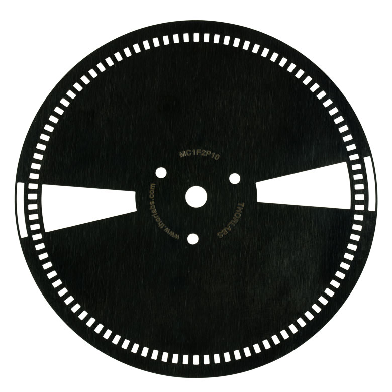 |
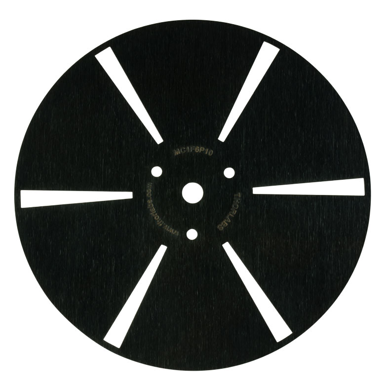 |
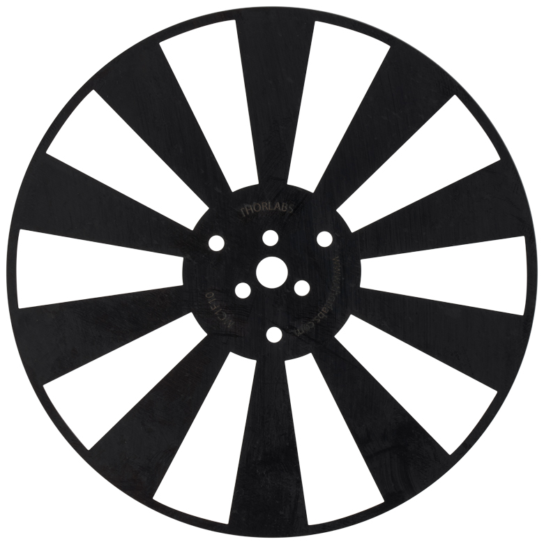 |
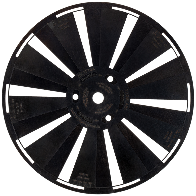 |
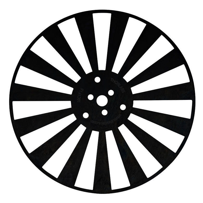 |
 |
 |
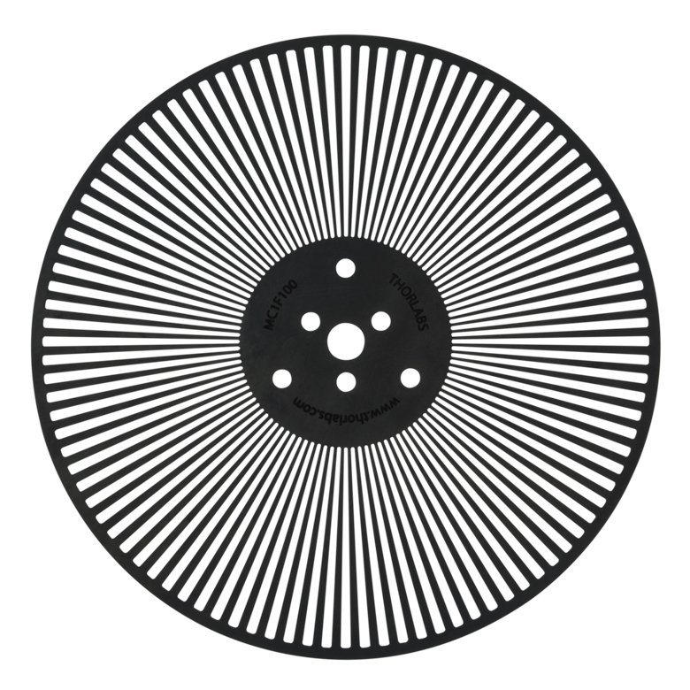 |
| Item # | MC1F10HPa | MC1F2b | MC1F2P10b | MC1F6P10 | MC1F10 | MC1F10Ac | MC1F15 | MC1F30 | MC1F60 | MC1F100 |
| Slots | 10, 100 | 2 | 2 | 6 | 10 | 10 | 15 | 30 | 60 | 100 |
| Duty Cycle | 50% | 10% | 50% | 0 - 50%c | 50% | |||||
| Frequency | 20 - 1000 Hz, 200 Hz - 10 kHz |
4 - 200 Hz | 4 - 200 Hz | 12 - 600 Hz | 20 - 1000 Hz | 20 - 1000 Hz | 30 - 1500 Hz | 60 - 3000 Hz | 120 - 6000 Hz | 200 Hz - 10 kHz |
| Compatible Chopper Systemd |
MC2000B | MC2000B MC2000 |
MC2000B | MC2000B | MC2000B MC2000 |
MC2000B | MC2000B MC2000 |
MC2000B MC2000 |
MC2000B MC2000 |
MC2000B MC2000 |
| Laser Beam Diametere | ||||||||||
| Max. Outsidef | 1.36 mmg (0.053") |
N/A | 11.68 mm (0.460") |
4.19 mm (0.165") |
13.23 mm (0.521") |
12.73 mmc (0.501") |
9.25 mm (0.364") |
4.86 mm (0.191") |
2.49 mm (0.098") |
1.51 mm (0.06") |
| Max. Centerh | 10.32 mm (0.406") |
26.10 mm (1.028") |
9.42 mm (0.371") |
2.77 mm (0.109") |
10.32 mm (0.406") |
10.03 mmc (0.395") |
6.90 mm (0.272") |
3.45 mm (0.136") |
1.73 mm (0.068") |
1.04 mm (0.04") |
| Max. Insidei | 6.34 mm (0.249") |
N/A | 6.35 mm (0.250") |
1.17 mm (0.046") |
6.34 mm (0.249") |
6.32 mmc (0.249") |
3.99 mm (0.157") |
1.89 mm (0.074") |
0.92 mm (0.036") |
0.55 mm (0.02") |

Click to Enlarge
Figure G2.1 Spot Size Reference Drawing
- Ideal for Ratiometric and Pump-Probe Experiments
- Blades Available for 8 Hz to 6 kHz Chopping Applications
- Support for Beam Diameters up to 14.66 mm
- Manufactured from 0.01" Thick Blue Clock Spring Steel
These harmonic frequency blades have inner and outer slots that allow a single beam to be split and individually modulated. Please see the Operation tab for more details. Our blades are manufactured from 0.01" thick blued clock spring steel. These blades are not compatible with our previous-generation MC2000 Optical Chopper.
| Product Photo (Click to Enlarge) |
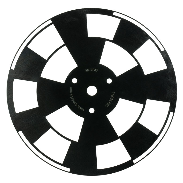 |
 |
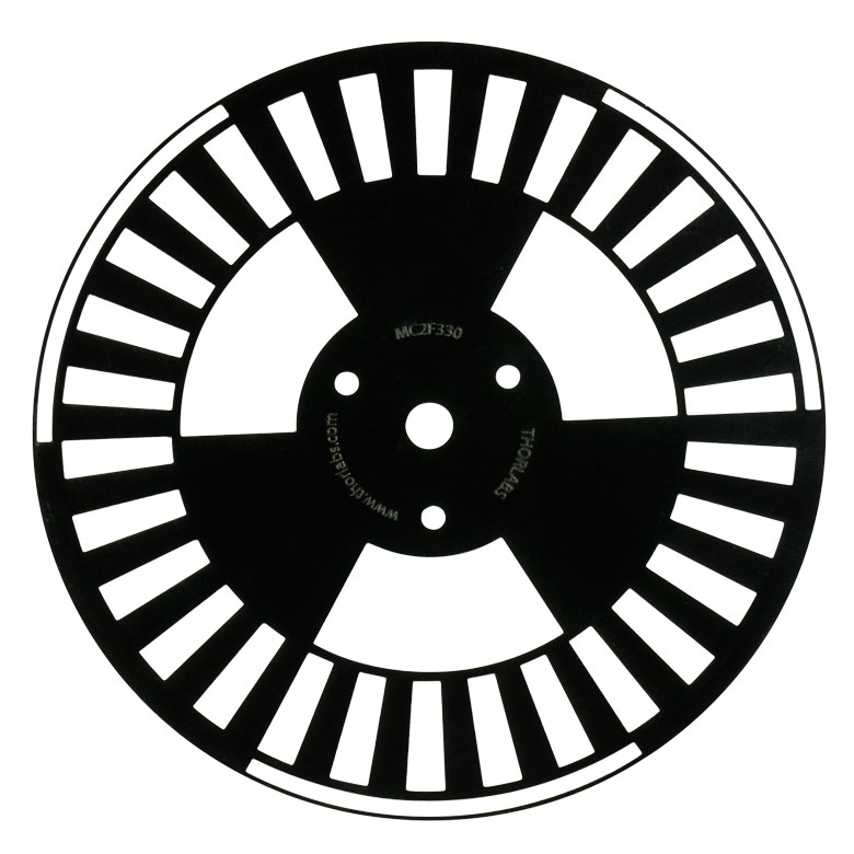 |
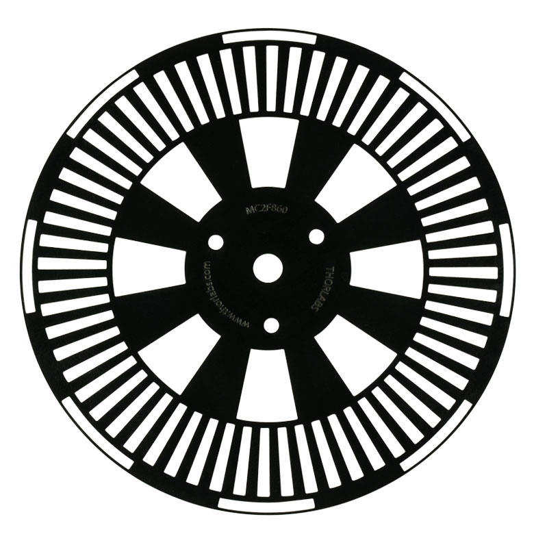 |
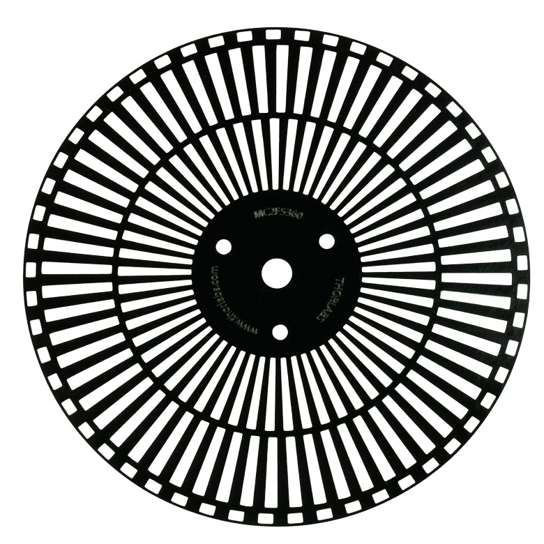 |
|
| Item # | MC2F47 | MC2F57Ba | MC2F330 | MC2F860 | MC2F5360 | |
| Slots | Inner | 4 | 5 | 3 | 8 | 53 |
| Outer | 7 | 7 | 30 | 60 | 60 | |
| Duty Cycle | 50% | |||||
| Frequency | Inner | 8 - 400 Hz | 10 - 500 Hz | 6 - 300 Hz | 16 - 800 Hz | 106 - 5300 Hz |
| Outer | 14 - 700 Hz | 14 - 700 Hz | 60 - 3000 Hz | 120 - 6000 Hz | 120 - 6000 Hz | |
| Laser Beam Diameter | ||||||
| Max. Beam Diameter | Inner | 14.66 mm (0.577") | 14.35 mm (0.565") | 14.66 mm (0.577”) | 9.53 mm (0.375”) | 1.45 mm (0.057”) |
| Outer | 13.97 mm (0.550") | 14.96 mm (0.589") | 4.19 mm (0.165”) | 2.08 mm (0.082”) | 2.08 mm (0.082”) | |