 Products Home
Picosecond Gain-Switched Lasers

- Center Wavelengths from 450 to 1550 nm
- Picosecond Pulses, Nanosecond Pulses, or CW Operation
- <130 ps Pulse Widths and Repetition Rates up to 200 MHz
- Compact Laser Systems with Fiber-Coupled Output
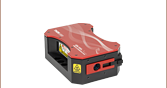
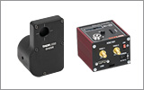
GSL106A
1064 nm Picosecond
Gain-Switched Laser
Key
Switch
Power
Supply
Connector
Interlock
Pulse
Controls
Trigger
In/Out


Please Wait
| Key Specificationsa | ||||
|---|---|---|---|---|
| Item # | Center Wavelength |
Pulse Widthb |
Peak Powerc |
Avg. Powerd |
| GSL45A | 450 ± 10 nm | <90 ps | >32 mW | >0.6 mW |
| 1 to 65 ns | 12 mW | - | ||
| GSL49A | 488 ± 10 nm | <120 ps | >29 mW | >0.7 mW |
| 1 to 65 ns | 12 mW | - | ||
| GSL52A | 520 ± 10 nm | <120 ps | >40 mW | >1.0 mW |
| 1 to 65 ns | 15 mW | - | ||
| GSL63A | 633 ± 10 nm | <130 ps | >75 mW | >2.0 mW |
| 1 to 65 ns | 35 mW | - | ||
| GSL85A | 850 ± 10 nm | <70 ps | >86 mW | >1.2 mW |
| 1 to 65 ns | 37.5 mW | |||
| GSL106A | 1064 ± 10 nm | <100 ps | >35 mW | >0.7 mW |
| 1 to 65 ns | 25 mW | - | ||
| GSL131A | 1310 ± 20 nm | <80 ps | >43 mW | >0.7 mW |
| 2 to 65 ns | 37.5 mW | - | ||
| GSL155A | 1550 ± 20 nm | <80 ps | >37 mW | >0.6 mW |
| 2 to 65 ns | 30 mW | - | ||
Applications
- Fluorescence Lifetime Imaging
- Time-Resolved Imaging
- Fiber Amplifier Seed Source
- Impulse Test and Measurement
- Quantum Key Distribution
Features
- 450 nm to 1550 nm Center Wavelengths
- <130 ps Pulse Width, 1 to 65 ns Pulse Widths, and CW Operation
- Fiber-Coupled Output with FC/APC Connector
- Precision Patch Cables Included for Lasers with Center Wavelengths ≤1064 nm
- Integrated Drive and Temperature Control Electronics
- Trigger Output for Pulse Synchronization
- Internal and External Triggering from Single Shot to 200 MHz
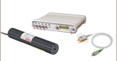
Thorlabs' GSL Series Gain-Switched Lasers provide picosecond, nanosecond, and continuous wave operation in compact, fiber-coupled, turnkey sources. Gain-switched pulse generation with adjustable pulse widths and repetition rates up to 200 MHz make these lasers suitable for high-speed imaging, fluorescence lifetime measurements, and impulse testing. GSL series lasers are also ideal seed sources for additional amplification using our range of fiber-based amplifiers.
The drive electronics and temperature control circuits for the laser diode are integrated into each device and are powered by an included DS15 power supply with region-specific plug. Single-mode fiber output through an FC/APC connector allows for integration with a wide range of fiber-terminated devices.
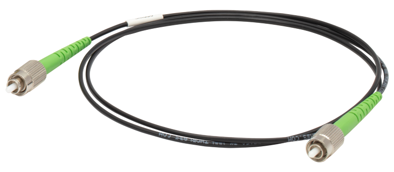
Patch Cables with Precision Connectors
GSL series lasers with mode-field diameters <7 μm include a fiber patch cable with precision connectors (Item #s GSL45A, GSL49A, GSL52A, GSL63A, GSL85A, GSL106A). Please see the Precision Patch Cables tab for details.
Pulse Width & Repetition Rate Controls
Each GSL series laser offers a control for varying the pulse width between picosecond operation (<130 ps), nanosecond operation adjustable over 14 discrete settings (1 to 65 ns), and continuous wave operation. Single shot operation is also available for pulse widths ≥6 ns. The pulse width control, located on the back panel, directly programs the pulse generator and can be adjusted to one of 16 positions using the included 2.5 mm screwdriver. Plots of typical pulse waveforms and typical pulse width as a function of the pulse width control setting are available in the Specs tab.
Alongside the pulse width control, the repetition rate control provides access to four internal and two external trigger settings, accommodating both Hi-Z and 50 Ω impedance connections. The internally available rates are 1 MHz, 10 MHz, 100 MHz, and 200 MHz. Use the included 2.5 mm flathead screwdriver to select the desired trigger setting. Note that pulse widths longer than 2 ns have maximum frequencies lower than 200 MHz, as illustrated in the diagram on the Specs tabs as well as in Section 4.5 of the manual.
Got Questions?
Our engineers and expertise are here for you!

Janis Valdmanis, Ph.D. Optics
Ultrafast Optoelectronics
General Manager
If you are not sure whether our catalog items meet your needs, we invite you to contact us. Or ask about a loan, so you can try them out for yourself, in your own lab. We can also support custom or OEM requirements you may have.
Just press the button, and we'll get back to you within the next business day.

Triggering
The female SMA Trigger In/Out port on the back panel has dual functions. If the internal oscillators are used, then the trigger port provides an output signal that is synchronized with the pulse generation. In the user-triggered mode, the SMA port allows external trigger signals to drive the pulse generator. Both a Hi-Z and 50 Ω user-triggered mode are available for low-frequency and high-frequency operation respectively.
Additional Front & Back Panel Features
A dual color (red/blue) emission LED on the front panel indicates when laser output is enabled and is designed to be visible through most laser safety glasses.
In addition to the trigger port, pulse width control, and repetition rate control, a multicolor status LED on the back panel indicates the operation state, including temperature stabilization and any errors. An engraved reference for the repetition rate options is also provided. Please see the Front & Back Panels tab and manual for more details about these features.
The GSL series lasers have built-in safety features including a key switch, interlock pin, and a four-second delay between the emission LED illuminating and laser output.
Electrical Connections
An external DS15 power supply with region-specific plugs is included with each laser. The laser integrates all other required drive electronics, safety interlocks, and temperature stabilization needed for operation; a block diagram with more details can be found on the Specs tab.
| Optical Specifications | |||||||||
|---|---|---|---|---|---|---|---|---|---|
| Item # | GSL45A | GSL49A | GSL52A | GSL63A | GSL85A | GSL106A | GSL131A | GSL155A | |
| Center Wavelength | 450 ±10 nm | 488 ± 10 nm | 520 ±10 nm | 633 ± 10 nm | 850 ± 10 nm | 1064 ± 10 nm | 1310 ± 20 nm | 1550 ± 20 nm | |
| Fiber Typea | 460HP | 460HP | 460HP | SM600 | 780HP | HI1060 | SMF-28 Ultra | SMF-28 Ultra | |
| Laser Class | 3B | 3B | 3B | 3B | 3B | 3B | 1M | 1M | |
| Output Connector | FC/APC, 2.0 mm Narrow Key | ||||||||
| Picosecond Pulse Operation | |||||||||
| Average Powerb | >0.6 mW | >0.7 mW | >1.0 mW | >2.0 mW | >1.2 mW | >0.7 mW | >0.7 mW | >0.6 mW | |
| Pulse Durationc | <90 ps | <120 ps | <120 ps | <130 ps | <70 ps | <100 ps | <80 ps | <80 ps | |
| Spectral Linewidth | <3 nm | <4 nm | <6 nm | <3 nm | <5 nm | <15 nm | <12 nm | <20 nm | |
| Repetition Rates | 200 kHz - 200 MHz | ||||||||
| Peak Power (Typ. Max) | >32 mW | >29 mW | >40 mW | >75 mW | >86 mW | >35 mW | >43 mW | >37 mW | |
| Power Stabilityd | <2% Over 8 Hours | ||||||||
| Nanosecond Pulse Operation | |||||||||
| Pulse Durationsc | 1 - 65 ns | 2 - 65 ns | |||||||
| Repetition Rates | Refer to the Graphic Belowe | ||||||||
| Peak Power (Typical) | 12 mW | 12 mW | 15 mW | 35 mW | 37.5 mW | 25 mW | 37.5 mW | 30 mW | |
| Continuous Wave (CW) Operation | |||||||||
| Average Power | 3 mW | 5 mW | 5 mW | 15 mW | 20 mW | ||||
| Typical Performance Plots (Click to View Plot) | |||||||||
| Typical Pulses | <130 ps |  |
 |
 |
 |
 |
 |
 |
 |
 |
 |
 |
 |
 |
 |
 |
|||
| Output Spectra | <130 ps |  |
 |
 |
 |
 |
 |
||
| 1 - 2 ns |  |
 |
 |
 |
 |
 |
 |
 |
|
| CW |  |
 |
 |
 |
 |
 |
 |
 |
|
| Pulse Width Control |  |
 |
 |
 |
 |
 |
|||
Click to Enlarge
The graphic above illustrates possible repetition rate ranges for each pulse width setting.
If the externally or internally provided repetition rate is outside of this range,
the Status LED on the rear of the device will flash amber.
| Trigger Specifications | ||
|---|---|---|
| Max Input Frequencya | 200 MHz | |
| Input Voltageb | 50 Ω (AC Coupled)c |
0.2 - 5.0 Vpp |
| Hi-Z, 5 kΩ (DC Coupled) | VIL = 0 - 0.8 V VIH = 2.2 - 5 V |
|
| Output Voltage | 50 Ω | 400 mV |
| Hi-Z | 800 mV | |
| Max Timing Jitterd | 12 ps RMS | |
| Delay from External Trigger Input to Optical Outpute | 44 ± 4 ns | |
| Delay from Internal Trigger Output to Optical Outpute | 3.4 ± 1.5 ns | |

Click to Enlarge
Block diagram depicting the internal architecture of the laser control system with drive electronics, safety interlocks, and temperature stabilization. The multicolored status LED indicator (red/green/amber) blinks during the 30 to 60 s warm up and glows continuously once temperature stability has been achieved.
| Power, Environmental, and Physical Specifications | |
|---|---|
| AC Input Frequency Range to DS15 Power Supply | 50 - 60 Hz |
| AC Input Voltage to DS15 Power Supply | 100 - 240 V |
| DC Input Voltage Range to Laser | 14.5 - 15.5 V |
| DC Input Current to Laser | 1100 mA Max |
| Operating Temperature Range | 10 to 45 °C |
| Storage Temperature Range | 0 to 60 °C |
| Humidity Range (RH) | 5% to 85% |
| Mass (Weight) | 0.80 kg (1.76 lbs) |
| Dimensions (L x W x H) | 185.6 mm x 100.0 mm x 39.4 mm (7.31" x 3.94" x 1.55") |
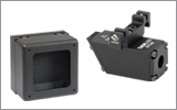
GSL Series Laser System Front and Back Panels
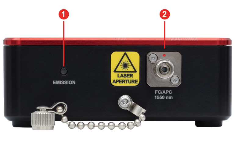
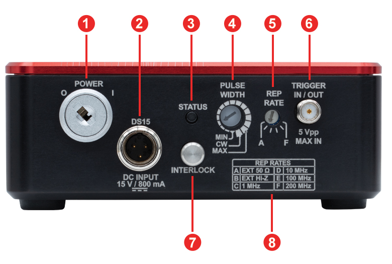
| Front Panel | |
|---|---|
| Call Out | Description |
| 1 | Laser Emission Status LED, Dual Color (Red/Blue) |
| 2 | FC/APC Fiber Bulkhead, 2.0 mm Narrow Key |
| Back Panel | |
|---|---|
| Call Out | Description |
| 1 | Power Key Switch |
| 2 | Male Mini-XLR Connector for the +15 V Power Supply Jack |
| 3 | Laser Status Indicator LED, Tri-Color (Red/Green/Amber) |
| 4 | Pulse Width Selectora |
| 5 | Repetition Rate Selectora |
| 6 | Trigger In/Trigger Out (Female SMA Connector) |
| 7 | Interlock Jack, 2.5 mm Mono Phono (Interlock Pin Installed) |
| 8 | Chart of Repetition Rate Options vs. Selector Settings |
Precision Patch Cables
Visible wavelengths present a challenge when attempting to mate together single-mode fibers. With mode-field diameters (MFD) less than 7 μm in these fibers, small deviations in core location can result in significant insertion loss. For example: in 460HP fiber with an MFD of 3.5 µm and operating at λ = 450 nm, a 1 µm misalignment can result in 1.5 dB of calculated insertion loss. To solve this challenge, we have provided pigtailed lasers with precision-located centers and matched patch cables that result in lower insertion loss. It should be noted that these improvements are not guaranteed when combined with standard fiber patch cables.
| Fiber Specifications | |||
|---|---|---|---|
| Item # | Fiber Type | Mode-Field Diameter | Includes Patch Cable |
| GSL45A | 460HP | 3.5 ± 0.5 µm @ 515 nm | Yes |
| Yes | |||
| GSL49A | |||
| Yes | |||
| GSL52A | |||
| GSL63A | SM600 | ||
| 3.6 to 5.3 µm @ 633 nma | Yes | ||
| GSL85A | 780HP | ||
| 5.0 ± 0.5 µm @ 850 nm | Yes | ||
| GSL106A | HI1060 | ||
| 6.2 ± 0.3 µm @ 1060 nm | Yes | ||
| GSL131A | SMF-28 Ultra | ||
| 9.2 ± 0.4 µm @ 1310 nm | No | ||
| GSL155A | 10.4 ± 0.5 µm @ 1550 nm | ||
Click to Enlarge
Included patch cable is 1 m long with a Ø2 mm jacket.
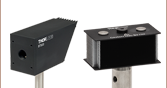
Fiber Patch Cable Mating for the GSL Series Lasers
The precision patch cables provided for these smaller MFD fibers have a highly centered core in a tight fitting ferrule, which has an inner diameter that closely matches the cladding diameter of the cable's terminated fiber. These two improvements avoid the core misalignment illustrated in the image to the lower left. The image on the lower right highlights the relative size difference between the SMF-28 Ultra and 460HP fibers, which have MFDs of 10.4 µm and 3.5 µm, respectively. The larger MFD of the SMF-28 Ultra fiber can accommodate a small amount of core misalignment without resulting in significant losses, while a smaller MFD requires tighter specifications on the core location to keep insertion losses low.
Click to Enlarge
Relative mode-field diameters are shown for SMF-28 Ultra and 460HP.

Click to Enlarge
Imperfect core centration in the fiber connector can result in high insertion loss when mating fibers (image not to scale).
Laser Safety and Classification
Safe practices and proper usage of safety equipment should be taken into consideration when operating lasers. The eye is susceptible to injury, even from very low levels of laser light. Thorlabs offers a range of laser safety accessories that can be used to reduce the risk of accidents or injuries. Laser emission in the visible and near infrared spectral ranges has the greatest potential for retinal injury, as the cornea and lens are transparent to those wavelengths, and the lens can focus the laser energy onto the retina.
 |
 |
 |
 |
 |
 |
 |
 |
 |
Safe Practices and Light Safety Accessories
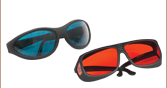
- Laser safety eyewear must be worn whenever working with Class 3 or 4 lasers.
- Regardless of laser class, Thorlabs recommends the use of laser safety eyewear whenever working with laser beams with non-negligible powers, since metallic tools such as screwdrivers can accidentally redirect a beam.
- Laser goggles designed for specific wavelengths should be clearly available near laser setups to protect the wearer from unintentional laser reflections.
- Goggles are marked with the wavelength range over which protection is afforded and the minimum optical density within that range.
- Laser Safety Curtains and Laser Safety Fabric shield other parts of the lab from high energy lasers.
- Blackout Materials can prevent direct or reflected light from leaving the experimental setup area.
- Thorlabs' Enclosure Systems can be used to contain optical setups to isolate or minimize laser hazards.
- A fiber-pigtailed laser should always be turned off before connecting it to or disconnecting it from another fiber, especially when the laser is at power levels above 10 mW.
- All beams should be terminated at the edge of the table, and laboratory doors should be closed whenever a laser is in use.
- Do not place laser beams at eye level.
- Carry out experiments on an optical table such that all laser beams travel horizontally.
- Remove unnecessary reflective items such as reflective jewelry (e.g., rings, watches, etc.) while working near the beam path.
- Be aware that lenses and other optical devices may reflect a portion of the incident beam from the front or rear surface.
- Operate a laser at the minimum power necessary for any operation.
- If possible, reduce the output power of a laser during alignment procedures.
- Use beam shutters and filters to reduce the beam power.
- Post appropriate warning signs or labels near laser setups or rooms.
- Use a laser sign with a lightbox if operating Class 3R or 4 lasers (i.e., lasers requiring the use of a safety interlock).
- Do not use Laser Viewing Cards in place of a proper Beam Trap.
Laser Classification
Lasers are categorized into different classes according to their ability to cause eye and other damage. The International Electrotechnical Commission (IEC) is a global organization that prepares and publishes international standards for all electrical, electronic, and related technologies. The IEC document 60825-1 outlines the safety of laser products. A description of each class of laser is given below:
| Class | Description | Warning Label |
|---|---|---|
| 1 | This class of laser is safe under all conditions of normal use, including use with optical instruments for intrabeam viewing. Lasers in this class do not emit radiation at levels that may cause injury during normal operation, and therefore the maximum permissible exposure (MPE) cannot be exceeded. Class 1 lasers can also include enclosed, high-power lasers where exposure to the radiation is not possible without opening or shutting down the laser. |  |
| 1M | Class 1M lasers are safe except when used in conjunction with optical components such as telescopes and microscopes. Lasers belonging to this class emit large-diameter or divergent beams, and the MPE cannot normally be exceeded unless focusing or imaging optics are used to narrow the beam. However, if the beam is refocused, the hazard may be increased and the class may be changed accordingly. |  |
| 2 | Class 2 lasers, which are limited to 1 mW of visible continuous-wave radiation, are safe because the blink reflex will limit the exposure in the eye to 0.25 seconds. This category only applies to visible radiation (400 - 700 nm). |  |
| 2M | Because of the blink reflex, this class of laser is classified as safe as long as the beam is not viewed through optical instruments. This laser class also applies to larger-diameter or diverging laser beams. |  |
| 3R | Class 3R lasers produce visible and invisible light that is hazardous under direct and specular-reflection viewing conditions. Eye injuries may occur if you directly view the beam, especially when using optical instruments. Lasers in this class are considered safe as long as they are handled with restricted beam viewing. The MPE can be exceeded with this class of laser; however, this presents a low risk level to injury. Visible, continuous-wave lasers in this class are limited to 5 mW of output power. |  |
| 3B | Class 3B lasers are hazardous to the eye if exposed directly. Diffuse reflections are usually not harmful, but may be when using higher-power Class 3B lasers. Safe handling of devices in this class includes wearing protective eyewear where direct viewing of the laser beam may occur. Lasers of this class must be equipped with a key switch and a safety interlock; moreover, laser safety signs should be used, such that the laser cannot be used without the safety light turning on. Laser products with power output near the upper range of Class 3B may also cause skin burns. |  |
| 4 | This class of laser may cause damage to the skin, and also to the eye, even from the viewing of diffuse reflections. These hazards may also apply to indirect or non-specular reflections of the beam, even from apparently matte surfaces. Great care must be taken when handling these lasers. They also represent a fire risk, because they may ignite combustible material. Class 4 lasers must be equipped with a key switch and a safety interlock. |  |
| All class 2 lasers (and higher) must display, in addition to the corresponding sign above, this triangular warning sign. |  |
|
Pulsed Laser Emission: Power and Energy Calculations

Determining whether emission from a pulsed laser is compatible with a device or application can require referencing parameters that are not supplied by the laser's manufacturer. When this is the case, the necessary parameters can typically be calculated from the available information. Calculating peak pulse power, average power, pulse energy, and related parameters can be necessary to achieve desired outcomes including:
- Protecting biological samples from harm.
- Measuring the pulsed laser emission without damaging photodetectors and other sensors.
- Exciting fluorescence and non-linear effects in materials.
Pulsed laser radiation parameters are illustrated in Figure 1 and described in the table. For quick reference, a list of equations are provided below. The document available for download provides this information, as well as an introduction to pulsed laser emission, an overview of relationships among the different parameters, and guidance for applying the calculations.
|
Equations: |
||||
 |
and |  |
||
 |
||||
 |
||||
 |
||||
Peak power and average power calculated from each other: |
||||
 |
and |  |
||
| Peak power calculated from average power and duty cycle*: | ||||
 |
*Duty cycle ( ) is the fraction of time during which there is laser pulse emission. ) is the fraction of time during which there is laser pulse emission. |
|||
Click to Enlarge
Figure 1: Parameters used to describe pulsed laser emission are indicated in the plot (above) and described in the table (below). Pulse energy (E) is the shaded area under the pulse curve. Pulse energy is, equivalently, the area of the diagonally hashed region.
| Parameter | Symbol | Units | Description | ||
|---|---|---|---|---|---|
| Pulse Energy | E | Joules [J] | A measure of one pulse's total emission, which is the only light emitted by the laser over the entire period. The pulse energy equals the shaded area, which is equivalent to the area covered by diagonal hash marks. | ||
| Period | Δt | Seconds [s] | The amount of time between the start of one pulse and the start of the next. | ||
| Average Power | Pavg | Watts [W] | The height on the optical power axis, if the energy emitted by the pulse were uniformly spread over the entire period. | ||
| Instantaneous Power | P | Watts [W] | The optical power at a single, specific point in time. | ||
| Peak Power | Ppeak | Watts [W] | The maximum instantaneous optical power output by the laser. | ||
| Pulse Width |  |
Seconds [s] | A measure of the time between the beginning and end of the pulse, typically based on the full width half maximum (FWHM) of the pulse shape. Also called pulse duration. | ||
| Repetition Rate | frep | Hertz [Hz] | The frequency with which pulses are emitted. Equal to the reciprocal of the period. | ||
Example Calculation:
Is it safe to use a detector with a specified maximum peak optical input power of 75 mW to measure the following pulsed laser emission?
- Average Power: 1 mW
- Repetition Rate: 85 MHz
- Pulse Width: 10 fs
The energy per pulse:

seems low, but the peak pulse power is:

It is not safe to use the detector to measure this pulsed laser emission, since the peak power of the pulses is >5 orders of magnitude higher than the detector's maximum peak optical input power.
| Posted Comments: | |
| No Comments Posted |