 Products Home / Optical Fiber & Fiber Patch Cables / Single Mode Fiber Optic Patch Cables / Single Mode FC/PC Fiber Optic Patch Cables
Single Mode FC/PC Fiber Optic Patch Cables
- SM Patch Cables for 320 to 2200 nm
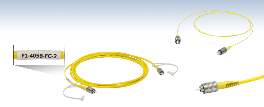
- Terminated on Both Ends with High-Quality Ceramic FC/PC Connectors
- Low Back-Reflection at Fiber-to-Fiber Junctions
- Typical Return Loss: 50 dB (40 dB min)
One End Labeled with Part
Number for Easy Identification
P1-405B-FC-2
405 - 532 nm Cable, Ø3 mm PVC Jacket,
2 m Long
FC/PC Connector
P1-780Y-FC-1
780 - 970 nm Cable,
Ø900 µm Hytrel® Jacket,
1 m Long


Please Wait
| Stock Single Mode Patch Cables Selection Guide | |
|---|---|
| Standard Cables | FC/PC to FC/PC |
| FC/APC to FC/APC | |
| Hybrid | |
| AR-Coated Patch Cables | |
| Thermally-Expanded-Core (TEC) Patch Cables | |
| HR-Coated Patch Cables | |
| Beamsplitter-Coated Patch Cables | |
| MIR Fluoride Fiber Patch Cables | |
Features
- SM Patch Cables for Signal Transmission from 320 nm to 2200 nm
- FC/PC 2.0 mm Narrow Key Connectors on Both Ends
- Low Back Reflections (High Return Loss): 50 dB (Typ.)
- Available from Stock
- Two Dust Caps Included
Thorlabs offers single mode patch cables with FC/PC connectors on both ends. Each cable is manufactured in our facility on state-of-the-art equipment. Available from stock, these cables feature either Ø3 mm PVC protective jackets or Ø900 µm Hytrel®* furcation tubing. The thinner profile of the Ø900 µm jacketed cables allows them to be used with our Manual Fiber Polarization Controllers.
Each patch cable includes two protective caps that shield the ferrule ends from dust and other contaminants. Additional CAPF Plastic Fiber Caps and CAPFM Metal Threaded Fiber Caps for FC/PC-terminated ends are also sold separately. Mating sleeves are available to connect FC to FC and FC to SMA connectors. These mating sleeves minimize back reflections and ensure proper alignment of the cores of each terminated fiber end.
Thorlabs also offers AR-Coated Single Mode Patch Cables, which have an antireflective coating on one fiber end for higher performance in fiber-to-free space applications. If you cannot find the appropriate stock patch cable your application requires, Thorlabs also offers custom patch cables with same-day shipping.
*Hytrel® is a registered trademark of DuPont Polymers, Inc.
| Item # Prefix | P1-305A | P1-405Y | P1-405 | P1-405B | P1-460Y | P1-460B |
|---|---|---|---|---|---|---|
| Fiber | SM300 | S405-XP | SM400 | SM450 | ||
| Operating Wavelength | 320 - 430 nm | 400 - 680 nm | 405 - 532 nm | 488 - 633 nma | ||
| Cutoff Wavelength | ≤310 nm | 380 ± 20 nm | 305 - 400 nm | 350 - 470 nma | ||
| Mode Field Diameter (MFD)b | 2.0 - 2.4 µm @ 350 nm | 3.3 ± 0.5 µm @ 405 nm 4.6 ± 0.5 µm @ 630 nm |
2.5 - 3.4 µm @ 480 nm | 2.8 - 4.1 µm @ 488 nm | ||
| Cladding Diameter | 125 ± 1.0 µm | 125 ± 1.0 µm | 125 ± 1.0 µm | 125 ± 1.0 µm | ||
| Coating Diameter | 245 ± 15 µm | 245 ± 15 µm | 245 ± 15 µm | 245 ± 15 µm | ||
| Attenuation (Max)c | ≤70 dB/km @ 350 nm | ≤30.0 dB/km @ 630 nm ≤30.0 dB/km @ 488 nm |
≤50 dB/km @ 430 nm ≤30 dB/km @ 532 nm |
≤50 dB/km @ 488 nmd | ||
| NA | 0.12 - 0.14 | 0.12 | 0.12 - 0.14 | 0.10 - 0.14 | ||
| Typical Insertion Losse (Click to Enlarge) |
 |
|||||
| Protective Jacketing | Ø3 mm Yellow PVC Furcation Tubing | Ø900 µm Yellow Hytrel®f Tubing | Ø3 mm Yellow PVC Furcation Tubing | Ø3 mm Yellow PVC Furcation Tubing | Ø900 µm Yellow Hytrel®f Tubing | Ø3 mm Yellow PVC Furcation Tubing |
| Return Loss | 50 dB Typical (40 dB Min) | |||||
| Connectors | FC/PC Narrow Key (2.0 mm) on Both Ends | |||||
| Lengthg | 1 m (for Item #s Ending in -1) 2 m (for Item #s Ending in -2) 5 m (for Item #s Ending in -5) 10 m (for Item #s Ending in -10) |
|||||
| Item # Prefix | P1-S630Y | P1-S630 | P1-630Y | P1-630A | P1-780Y | P1-780A | P1-830A | P1-980A |
|---|---|---|---|---|---|---|---|---|
| Fiber | S630-HP | SM600 | 780HP | SM800-5.6-125 | SM980-5.8-125 | |||
| Operating Wavelength | 630 - 860 nm | 633 - 780 nma | 780 - 970 nm | 830 - 980 nm | 980 - 1550 nma | |||
| Cutoff Wavelength | 590 ± 30 nm | 500 - 600 nm | 730 ± 30 nm | 660 - 800 nm | 870 - 970 nm | |||
| Mode Field Diameter (MFD)b | 4.2 ± 0.5 µm @ 630 nm | 3.6 - 5.3 µm @ 633 nm | 5.0 ± 0.5 µm @ 850 nm | 4.7 - 6.9 µm @ 830 nm | 5.3 - 6.4 µm @ 980 nm |
|||
| Cladding Diameter | 125 ± 1.0 µm | 125 ± 1.0 µm | 125 ± 1 µm | 125 ± 1.0 µm | 125 ± 1.0 µm | |||
| Coating Diameter | 245 ± 15 µm | 245 ± 15 µm | 245 ± 15 µm | 245 ± 15 µm | 245 ± 15 µm | |||
| Attenuation (Max)c | ≤10 dB/km @ 630 nm | ≤15 dB/kmd | <3.5 dB/km @ 780 nm | <5 dB/kmd | ≤2.0 dB/kmd | |||
| NA | 0.12 | 0.10 - 0.14 | 0.13 | 0.10 - 0.14 | 0.13 - 0.15 | |||
| Typical Insertion Losse (Click to Enlarge) |
|
|||||||
| Protective Jacketing | Ø900 µm Yellow Hytrel®f Tubing |
Ø3 mm Yellow PVC Furcation Tubing |
Ø900 µm Yellow Hytrel®f Tubing |
Ø3 mm Yellow PVC Furcation Tubing |
Ø900 µm Yellow Hytrel® Tubing |
Ø3 mm Yellow PVC Furcation Tubing |
Ø3 mm Yellow PVC Furcation Tubing |
|
| Return Loss | 50 dB Typical (40 dB Min) | |||||||
| Connectors | FC/PC Narrow Key (2.0 mm) on Both Ends | |||||||
| Lengthg | 1 m (for Item #s Ending in -1) 2 m (for Item #s Ending in -2) 5 m (for Item #s Ending in -5) 10 m (for Item #s Ending in -10) |
|||||||
| Item # Prefix | P1-1064Y | P1-1064 | P1-SMF28Y | P1-SMF28E | P1-1550A | P1-1950 |
|---|---|---|---|---|---|---|
| Fiber | HI1060-J9 | SMF-28 Ultra | 1550BHP | SM1950 | ||
| Operating Wavelength | 980 - 1650 nm | 1260 - 1625 nm | 1460 - 1620 nm | 1850 - 2200 nm | ||
| Cutoff Wavelength | 920 ± 50 nm | <1260 nm | 1400 ± 50 nm | 1720 ± 80 nm | ||
| Mode Field Diameter (MFD)a | 5.9 ± 0.3 µm @ 980 nm 6.2 ± 0.3 µm @ 1060 nm |
9.2 ± 0.4 µm @ 1310 nm 10.4 ± 0.5 µm @ 1550 nm |
9.5 ± 0.5 µm @ 1550 nm | 8.0 µm @ 1950 nm | ||
| Cladding Diameter | 125 ± 0.5 µm | 125 ± 0.7 µm | 125 ± 1 µm | 125 ± 1 µm | ||
| Coating Diameter | 245 ± 10 µm | 242 ± 5 µm | 245 ± 15 µm | 245 ± 10 µm | ||
| Attenuationb | 2.1 dB/km @ 980 nm (Max) 1.5 dB/km @1060 nm (Max) |
≤0.32 dB/km @ 1310 nm (Max) ≤0.18 dB/km @ 1550 nm (Max) |
0.5 dB/km @ 1550 nm (Max) | 5 dB/km @ 1900 nm (Typical) | ||
| NA | 0.14 | 0.14 | 0.13 | 0.20 | ||
| Typical Insertion Lossc (Click to Enlarge) |
|
|||||
| Protective Jacketing | Ø900 µm Yellow Hytrel®d Tubing |
Ø3 mm Yellow PVC Furcation Tubing |
Ø900 µm Yellow Hytrel® Tubing |
Ø3 mm Yellow PVC Furcation Tubing |
Ø3 mm Yellow PVC Furcation Tubing |
|
| Return Loss | 50 dB Typical (40 dB Min) | |||||
| Connectors | FC/PC Narrow Key (2.0 mm) on Both Ends | |||||
| Lengthe | 1 m (for Item #s Ending in -1) 2 m (for Item #s Ending in -2) 5 m (for Item #s Ending in -5) 10 m (for Item #s Ending in -10) |
|||||
Click to Enlarge
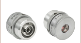
Mating Between a Narrow-Key Mating Sleeve and Connector
Click to Enlarge
Mating Between a Wide-Key Mating Sleeve and Connector
FC/PC and FC/APC Patch Cable Key Alignment
FC/PC and FC/APC Patch Cables are equipped with either a 2.0 mm narrow or 2.2 mm wide alignment key that fits into a corresponding slot on a mated component. These keys and slots are essential to correctly align the cores of connected fiber patch cables and minimize the insertion loss of the connection.
As an example, Thorlabs designs and manufactures mating sleeves for FC/PC- and FC/APC-terminated patch cables to precise specifications that ensure good alignment when used correctly. To ensure the best alignment, the alignment key on the patch cable is inserted into the corresponding narrow or wide-key slot on the mating sleeve.
Wide-Key-Slot Mating Sleeves
2.2 mm wide-key-slot mating sleeves are compatible with both wide-key and narrow-key connectors. However, using a narrow-key connector in a wide-key slot will allow the connector to rotate slightly in the mating sleeve (as shown in the animation below and to the left). While this configuration is acceptable for patch cables with FC/PC connectors, for FC/APC applications, we recommend using narrow-key-slot mating sleeves to ensure optimum alignment.
Narrow-Key-Slot Mating Sleeves
2.0 mm narrow-key-slot mating sleeves allow for optimal alignment of angled, narrow-key FC/APC connectors, as shown in the animation below and to the right. Therefore, they are not compatible with connectors that have a 2.2 mm wide key. Please note that all FC/PC and FC/APC patch cables manufactured by Thorlabs use narrow key connectors.
Once a narrow key connector is inserted into a narrow-key-slot mating sleeve, the connector will not rotate. We therefore recommend these mating sleeves for FC/PC and FC/APC connectors with narrow keys.
When a narrow key connector is inserted into a wide-key-slot mating sleeve, the connector has room to rotate. For narrow key FC/PC connectors, this is acceptable, but for narrow key FC/APC connectors, significant coupling losses will result.
| Quick Links |
|---|
| Damage at the Air / Glass Interface |
| Intrinsic Damage Threshold |
| Preparation and Handling of Optical Fibers |
Laser-Induced Damage in Silica Optical Fibers
The following tutorial details damage mechanisms relevant to unterminated (bare) fiber, terminated optical fiber, and other fiber components from laser light sources. These mechanisms include damage that occurs at the air / glass interface (when free-space coupling or when using connectors) and in the optical fiber itself. A fiber component, such as a bare fiber, patch cable, or fused coupler, may have multiple potential avenues for damage (e.g., connectors, fiber end faces, and the device itself). The maximum power that a fiber can handle will always be limited by the lowest limit of any of these damage mechanisms.
While the damage threshold can be estimated using scaling relations and general rules, absolute damage thresholds in optical fibers are very application dependent and user specific. Users can use this guide to estimate a safe power level that minimizes the risk of damage. Following all appropriate preparation and handling guidelines, users should be able to operate a fiber component up to the specified maximum power level; if no maximum is specified for a component, users should abide by the "practical safe level" described below for safe operation of the component. Factors that can reduce power handling and cause damage to a fiber component include, but are not limited to, misalignment during fiber coupling, contamination of the fiber end face, or imperfections in the fiber itself. For further discussion about an optical fiber’s power handling abilities for a specific application, please contact Thorlabs’ Tech Support.
Click to Enlarge
Undamaged Fiber End
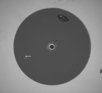
Click to Enlarge
Damaged Fiber End
Damage at the Air / Glass Interface
There are several potential damage mechanisms that can occur at the air / glass interface. Light is incident on this interface when free-space coupling or when two fibers are mated using optical connectors. High-intensity light can damage the end face leading to reduced power handling and permanent damage to the fiber. For fibers terminated with optical connectors where the connectors are fixed to the fiber ends using epoxy, the heat generated by high-intensity light can burn the epoxy and leave residues on the fiber facet directly in the beam path.
| Estimated Optical Power Densities on Air / Glass Interfacea | ||
|---|---|---|
| Type | Theoretical Damage Thresholdb | Practical Safe Levelc |
| CW (Average Power) |
~1 MW/cm2 | ~250 kW/cm2 |
| 10 ns Pulsed (Peak Power) |
~5 GW/cm2 | ~1 GW/cm2 |
Damage Mechanisms on the Bare Fiber End Face
Damage mechanisms on a fiber end face can be modeled similarly to bulk optics, and industry-standard damage thresholds for UV Fused Silica substrates can be applied to silica-based fiber. However, unlike bulk optics, the relevant surface areas and beam diameters involved at the air / glass interface of an optical fiber are very small, particularly for coupling into single mode (SM) fiber. therefore, for a given power density, the power incident on the fiber needs to be lower for a smaller beam diameter.
The table to the right lists two thresholds for optical power densities: a theoretical damage threshold and a "practical safe level". In general, the theoretical damage threshold represents the estimated maximum power density that can be incident on the fiber end face without risking damage with very good fiber end face and coupling conditions. The "practical safe level" power density represents minimal risk of fiber damage. Operating a fiber or component beyond the practical safe level is possible, but users must follow the appropriate handling instructions and verify performance at low powers prior to use.
Calculating the Effective Area for Single Mode Fibers
The effective area for single mode (SM) fiber is defined by the mode field diameter (MFD), which is the cross-sectional area through which light propagates in the fiber; this area includes the fiber core and also a portion of the cladding. To achieve good efficiency when coupling into a single mode fiber, the diameter of the input beam must match the MFD of the fiber.
As an example, SM400 single mode fiber has a mode field diameter (MFD) of ~Ø3 µm operating at 400 nm, while the MFD for SMF-28 Ultra single mode fiber operating at 1550 nm is Ø10.5 µm. The effective area for these fibers can be calculated as follows:
SM400 Fiber: Area = Pi x (MFD/2)2 = Pi x (1.5 µm)2 = 7.07 µm2 = 7.07 x 10⁻⁸ cm2
SMF-28 Ultra Fiber: Area = Pi x (MFD/2)2 = Pi x (5.25 µm)2 = 86.6 µm2 = 8.66 x 10⁻⁷ cm2
To estimate the power level that a fiber facet can handle, the power density is multiplied by the effective area. Please note that this calculation assumes a uniform intensity profile, but most laser beams exhibit a Gaussian-like shape within single mode fiber, resulting in a higher power density at the center of the beam compared to the edges. Therefore, these calculations will slightly overestimate the power corresponding to the damage threshold or the practical safe level. Using the estimated power densities assuming a CW light source, we can determine the corresponding power levels as:
SM400 Fiber: 7.07 x 10⁻⁸ cm2 x 1 MW/cm2 = 7.1 x 10⁻⁸ MW = 71 mW (Theoretical Damage Threshold)
7.07 x 10⁻⁸ cm2 x 250 kW/cm2 = 1.8 x 10⁻⁵ kW = 18 mW (Practical Safe Level)
SMF-28 Ultra Fiber: 8.66 x 10⁻⁷ cm2 x 1 MW/cm2 = 8.7 x 10⁻⁷ MW = 870 mW (Theoretical Damage Threshold)
8.66 x 10⁻⁷ cm2 x 250 kW/cm2 = 2.1 x 10⁻⁴ kW = 210 mW (Practical Safe Level)
Effective Area of Multimode Fibers
The effective area of a multimode (MM) fiber is defined by the core diameter, which is typically far larger than the MFD of an SM fiber. For optimal coupling, Thorlabs recommends focusing a beam to a spot roughly 70 - 80% of the core diameter. The larger effective area of MM fibers lowers the power density on the fiber end face, allowing higher optical powers (typically on the order of kilowatts) to be coupled into multimode fiber without damage.
Damage Mechanisms Related to Ferrule / Connector Termination
 Click to Enlarge
Plot showing approximate input power that can be incident on a single mode silica optical fiber with a termination. Each line shows the estimated power level due to a specific damage mechanism. The maximum power handling is limited by the lowest power level from all relevant damage mechanisms (indicated by a solid line).
Fibers terminated with optical connectors have additional power handling considerations. Fiber is typically terminated using epoxy to bond the fiber to a ceramic or steel ferrule. When light is coupled into the fiber through a connector, light that does not enter the core and propagate down the fiber is scattered into the outer layers of the fiber, into the ferrule, and the epoxy used to hold the fiber in the ferrule. If the light is intense enough, it can burn the epoxy, causing it to vaporize and deposit a residue on the face of the connector. This results in localized absorption sites on the fiber end face that reduce coupling efficiency and increase scattering, causing further damage.
For several reasons, epoxy-related damage is dependent on the wavelength. In general, light scatters more strongly at short wavelengths than at longer wavelengths. Misalignment when coupling is also more likely due to the small MFD of short-wavelength SM fiber that also produces more scattered light.
To minimize the risk of burning the epoxy, fiber connectors can be constructed to have an epoxy-free air gap between the optical fiber and ferrule near the fiber end face. Our high-power multimode fiber patch cables use connectors with this design feature.
Determining Power Handling with Multiple Damage Mechanisms
When fiber cables or components have multiple avenues for damage (e.g., fiber patch cables), the maximum power handling is always limited by the lowest damage threshold that is relevant to the fiber component. In general, this represents the highest input power that can be incident on the patch cable end face and not the coupled output power.
As an illustrative example, the graph to the right shows an estimate of the power handling limitations of a single mode fiber patch cable due to damage to the fiber end face and damage via an optical connector. The total input power handling of a terminated fiber at a given wavelength is limited by the lower of the two limitations at any given wavelength (indicated by the solid lines). A single mode fiber operating at around 488 nm is primarily limited by damage to the fiber end face (blue solid line), but fibers operating at 1550 nm are limited by damage to the optical connector (red solid line).
In the case of a multimode fiber, the effective mode area is defined by the core diameter, which is larger than the effective mode area for SM fiber. This results in a lower power density on the fiber end face and allows higher optical powers (on the order of kilowatts) to be coupled into the fiber without damage (not shown in graph). However, the damage limit of the ferrule / connector termination remains unchanged and as a result, the maximum power handling for a multimode fiber is limited by the ferrule and connector termination.
Please note that these are rough estimates of power levels where damage is very unlikely with proper handling and alignment procedures. It is worth noting that optical fibers are frequently used at power levels above those described here. However, these applications typically require expert users and testing at lower powers first to minimize risk of damage. Even still, optical fiber components should be considered a consumable lab supply if used at high power levels.
Intrinsic Damage Threshold
In addition to damage mechanisms at the air / glass interface, optical fibers also display power handling limitations due to damage mechanisms within the optical fiber itself. These limitations will affect all fiber components as they are intrinsic to the fiber itself. Two categories of damage within the fiber are damage from bend losses and damage from photodarkening.
Bend Losses
Bend losses occur when a fiber is bent to a point where light traveling in the core is incident on the core/cladding interface at an angle higher than the critical angle, making total internal reflection impossible. Under these circumstances, light escapes the fiber, often in a localized area. The light escaping the fiber typically has a high power density, which burns the fiber coating as well as any surrounding furcation tubing.
A special category of optical fiber, called double-clad fiber, can reduce the risk of bend-loss damage by allowing the fiber’s cladding (2nd layer) to also function as a waveguide in addition to the core. By making the critical angle of the cladding/coating interface higher than the critical angle of the core/clad interface, light that escapes the core is loosely confined within the cladding. It will then leak out over a distance of centimeters or meters instead of at one localized spot within the fiber, minimizing the risk of damage. Thorlabs manufactures and sells 0.22 NA double-clad multimode fiber, which boasts very high, megawatt range power handling.
Photodarkening
A second damage mechanism, called photodarkening or solarization, can occur in fibers used with ultraviolet or short-wavelength visible light, particularly those with germanium-doped cores. Fibers used at these wavelengths will experience increased attenuation over time. The mechanism that causes photodarkening is largely unknown, but several fiber designs have been developed to mitigate it. For example, fibers with a very low hydroxyl ion (OH) content have been found to resist photodarkening and using other dopants, such as fluorine, can also reduce photodarkening.
Even with the above strategies in place, all fibers eventually experience photodarkening when used with UV or short-wavelength light, and thus, fibers used at these wavelengths should be considered consumables.
Preparation and Handling of Optical Fibers
General Cleaning and Operation Guidelines
These general cleaning and operation guidelines are recommended for all fiber optic products. Users should still follow specific guidelines for an individual product as outlined in the support documentation or manual. Damage threshold calculations only apply when all appropriate cleaning and handling procedures are followed.
-
All light sources should be turned off prior to installing or integrating optical fibers (terminated or bare). This ensures that focused beams of light are not incident on fragile parts of the connector or fiber, which can possibly cause damage.
-
The power-handling capability of an optical fiber is directly linked to the quality of the fiber/connector end face. Always inspect the fiber end prior to connecting the fiber to an optical system. The fiber end face should be clean and clear of dirt and other contaminants that can cause scattering of coupled light. Bare fiber should be cleaved prior to use and users should inspect the fiber end to ensure a good quality cleave is achieved.
-
If an optical fiber is to be spliced into the optical system, users should first verify that the splice is of good quality at a low optical power prior to high-power use. Poor splice quality may increase light scattering at the splice interface, which can be a source of fiber damage.
-
Users should use low power when aligning the system and optimizing coupling; this minimizes exposure of other parts of the fiber (other than the core) to light. Damage from scattered light can occur if a high power beam is focused on the cladding, coating, or connector.
Tips for Using Fiber at Higher Optical Power
Optical fibers and fiber components should generally be operated within safe power level limits, but under ideal conditions (very good optical alignment and very clean optical end faces), the power handling of a fiber component may be increased. Users must verify the performance and stability of a fiber component within their system prior to increasing input or output power and follow all necessary safety and operation instructions. The tips below are useful suggestions when considering increasing optical power in an optical fiber or component.
-
Splicing a fiber component into a system using a fiber splicer can increase power handling as it minimizes possibility of air/fiber interface damage. Users should follow all appropriate guidelines to prepare and make a high-quality fiber splice. Poor splices can lead to scattering or regions of highly localized heat at the splice interface that can damage the fiber.
-
After connecting the fiber or component, the system should be tested and aligned using a light source at low power. The system power can be ramped up slowly to the desired output power while periodically verifying all components are properly aligned and that coupling efficiency is not changing with respect to optical launch power.
-
Bend losses that result from sharply bending a fiber can cause light to leak from the fiber in the stressed area. When operating at high power, the localized heating that can occur when a large amount of light escapes a small localized area (the stressed region) can damage the fiber. Avoid disturbing or accidently bending fibers during operation to minimize bend losses.
-
Users should always choose the appropriate optical fiber for a given application. For example, large-mode-area fibers are a good alternative to standard single mode fibers in high-power applications as they provide good beam quality with a larger MFD, decreasing the power density on the air/fiber interface.
-
Step-index silica single mode fibers are normally not used for ultraviolet light or high-peak-power pulsed applications due to the high spatial power densities associated with these applications.

Insights into Optical Fiber
Scroll down to read about:
- When does NA provide a good estimate of the fiber's acceptance angle?
- Why is MFD an important coupling parameter for single mode fibers?
- Does NA provide a good estimate of beam divergence from a single mode fiber?
Click here for more insights into lab practices and equipment.
When does NA provide a good estimate of the fiber's acceptance angle?

Click to Enlarge
Figure 1: Rays incident at angles ≤θmax will be captured by the cores of multimode fiber, since these rays experience total internal reflection at the interface between core and cladding.
Click to Enlarge
Figure 2: The behavior of the ray at the boundary between the core and cladding, which depends on their refractive indices, determines whether the ray incident on the end face is coupled into the core. The equation for NA can be found using geometry and the two equations noted at the top of this figure.
Numerical aperture (NA) provides a good estimate of the maximum acceptance angle for most multimode fibers, as shown in Figure 1. This relationship should not be used for single mode fibers.
NA and Acceptance Angle
Incident light is modeled as rays to obtain the relationship between NA and the maximum acceptance angle (θmax ), which describes the fiber's ability to gather light from off-axis sources. The equation at the top of Figure 1 can be used to determine whether rays traced from different light sources will be coupled into the fiber's core.
Rays with an angle of incidence ≤θmax are totally internally reflected (TIR) at the boundary between the fiber's core and cladding. As these rays propagate down the fiber, they remain trapped in the core.
Rays with angles of incidence larger than θmax refract at the interface between core and cladding, and this light is eventually lost from the fiber.
Geometry Defines the Relationship
The relationship among NA, θmax , and the refractive indices of the core and cladding, ncore and nclad , respectively, can be found using the geometry diagrammed in Figure 2. This geometry illustrates the most extreme conditions under which TIR will occur at the boundary between the core and cladding.
The equations at the top of Figure 2 are expressions of Snell's law and describe the rays' behavior at both interfaces. Note that the simplification sin(90°) = 1 has been used. Only the indices of the core and cladding limit the value of θmax .
Angles of Incidence and Fiber Modes
When the angle of incidence is ≤θmax , the incident light ray is coupled into one of the multimode fiber's guided modes. Generally speaking, the lower the angle of incidence, the lower the order of the excited fiber mode. Lower-order modes concentrate most of their intensity near the center of the core. The lowest order mode is excited by rays incident normally on the end face.
Single Mode Fibers are Different
In the case of single mode fibers, the ray model in Figure 2 is not useful, and the calculated NA (acceptance angle) does not equal the maximum angle of incidence or describe the fiber's light gathering ability.
Single mode fibers have only one guided mode, the lowest order mode, which is excited by rays with 0° angles of incidence. However, calculating the NA results in a nonzero value. The ray model also does not accurately predict the divergence angles of the light beams successfully coupled into and emitted from single mode fibers. The beam divergence occurs due to diffraction effects, which are not taken into account by the ray model but can be described using the wave optics model. The Gaussian beam propagation model can be used to calculate beam divergence with high accuracy.
Date of Last Edit: Jan. 20, 2020
Why is MFD an important coupling parameter for single mode fibers?
Click to Enlarge
Figure 3 For maximum coupling efficiency into single mode fibers, the light should be an on-axis Gaussian beam with its waist located at the fiber's end face, and the waist diameter should equal the MFD. The beam output by the fiber also resembles a Gaussian with these characteristics. In the case of single mode fibers, the ray optics model and NA are inadequate for determining coupling conditions. The mode intensity (I ) profile across the radius ( ρ ) is illustrated.
As light propagates down a single mode fiber, the beam maintains a cross sectional profile that is nearly Gaussian in shape. The mode field diameter (MFD) describes the width of this intensity profile. The better an incident beam matches this intensity profile, the larger the fraction of light coupled into the fiber. An incident Gaussian beam with a beam waist equal to the MFD can achieve particularly high coupling efficiency.
Using the MFD as the beam waist in the Gaussian beam propagation model can provide highly accurate incident beam parameters, as well as the output beam's divergence.
Determining Coupling Requirements
A benefit of optical fibers is that light carried by the fibers' guided mode(s) does not spread out radially and is minimally attenuated as it propagates. Coupling light into one of a fiber's guided modes requires matching the characteristics of the incident light to those of the mode. Light that is not coupled into a guided mode radiates out of the fiber and is lost. This light is said to leak out of the fiber.
Single mode fibers have one guided mode, and wave optics analysis reveals the mode to be described by a Bessel function. The amplitude profiles of Gaussian and Bessel functions closely resemble one another, which is convenient since using a Gaussian function as a substitute simplifies the modeling the fiber's mode while providing accurate results (Kowalevicz).
Figure 3 illustrates the single mode fiber's mode intensity cross section, which the incident light must match in order to couple into the guided mode. The intensity (I ) profile is a near-Gaussian function of radial distance ( ρ ). The MFD, which is constant along the fiber's length, is the width measured at an intensity equal to the product of e-2 and the peak intensity. The MFD encloses ~86% of the beam's power.
Since lasers emitting only the lowest-order transverse mode provide Gaussian beams, this laser light can be efficiently coupled into single mode fibers.
Coupling Light into the Single Mode Fiber
To efficiently couple light into the core of a single-mode fiber, the waist of the incident Gaussian beam should be located at the fiber's end face. The intensity profile of the beam's waist should overlap and match the characteristics of the mode intensity cross section. The required incident beam parameters can be calculated using the fiber's MFD with the Gaussian beam propagation model.
The coupling efficiency will be reduced if the beam waist is a different diameter than the MFD, the cross-sectional profile of the beam is distorted or shifted with respect to the modal spot at the end face, and / or if the light is not directed along the fiber's axis.
References
Kowalevicz A and Bucholtz F, "Beam Divergence from an SMF-28 Optical Fiber (NRL/MR/5650--06-8996)." Naval Research Laboratory, 2006.
Date of Last Edit: Feb. 28, 2020
Why is MFD an important coupling parameter for single mode fibers?
Significant error can result when the numerical aperture (NA) is used to estimate the cone of light emitted from, or that can be coupled into, a single mode fiber. A better estimate is obtained using the Gaussian beam propagation model to calculate the divergence angle. This model allows the divergence angle to be calculated for whatever beam spot size best suits the application.
Since the mode field diameter (MFD) specified for single mode optical fibers encloses ~86% of the beam power, this definition of spot size is often appropriate when collimating light from and focusing light into a single mode fiber. In this case, to a first approximation and when measured in the far field,
 , , |
(1) |
is the divergence or acceptance angle (θSM ), in radians. This is half the full angular extent of the beam, it is wavelength  )
)
| Rayleigh Range: | ||
 |
||
| Beam Radius at Distance z: | ||
 |
||
|
Figure 4: These curves illustrate the consequence of using NA to calculate the divergence (θSM ) of light output from a single mode fiber. Significant error in beam spot diameter can be avoided by using the Gaussian beam propagation model. This plot models a beam from SM980-5.8-125. The values used for NA and MFD were 0.13 and 6.4 µm, respectively. The operating wavelength was 980 nm, and the Rayleigh range was 32.8 µm. |
||
Gaussian Beam Approach
Although a diverging cone of light is emitted from the end face of a single mode optical fiber, this light does not behave as multiple rays travelling at different angles to the fiber's axis.
Instead, this light resembles and can be modeled as a single Gaussian beam. The emitted light propagates similarly to a Gaussian beam since the guided fiber mode that carried the light has near-Gaussian characteristics.
The divergence angle of a Gaussian beam can differ substantially from the angle calculated by assuming the light behaves as rays. Using the ray model, the divergence angle would equal sin-1(NA). However, the relationship between NA and divergence angle is only valid for highly multimode fibers.
Figure 4 illustrates that using the NA to estimate the divergence angle can result in significant error. In this case, the divergence angle was needed for a point on the circle enclosing 86% of the beam's optical power. The intensity of a point on this circle is a factor of 1/e2 lower than the peak intensity.
The equations to the right of the plot in Figure 4 were used to accurately model the divergence of the beam emitted from the single mode fiber's end face. The values used to complete the calculations, including the fiber's MFD, NA, and operating wavelength are given in the figure's caption. This rate of beam divergence assumes a beam size defined by the 1/e2 radius, is nonlinear for distances z < zR, and is approximately linear in the far field (z >> zR).
The angles noted on the plot were calculated from each curve's respective slope. When the far field approximation given by Equation (1) is used, the calculated divergence angle is 0.098 radians (5.61°).
References
Kowalevicz A and Bucholtz F, "Beam Divergence from an SMF-28 Optical Fiber (NRL/MR/5650--06-8996)." Naval Research Laboratory, 2006.
Date of Last Edit: Feb. 28, 2020
Content improved by our readers!
| Posted Comments: | |
Jaya Sagar
(posted 2024-02-15 16:00:30.997) Hi, Can you make a SMF, FC/PC, 900um coating, 780-970nm, patch cable of a custom length - 219mm for us ? jdelia
(posted 2024-02-15 01:59:54.0) Thank you for contacting Thorlabs. I have reached out to you directly to discuss the feasibility of this customized item request. Alois Mair
(posted 2023-11-20 15:06:30.78) What ist the operation or cutoff wavelength? We still have and use them in our labs. jdelia
(posted 2023-11-22 11:51:31.0) Thank you for contacting Thorlabs. The cable you are referring to is the P1-3224-FC-2, which was made out of our obsolete FS-SN-3224 fiber. You can find the catalog presentation, which includes the specs of the fiber, in the "Catalog Presentation" from the following link: https://www.thorlabs.com/thorproduct.cfm?partnumber=FS-SN-3224 Jisoo Kyoung
(posted 2023-06-27 12:49:02.677) Dear Thorlabs,
Hello, I am interested in your fiber: P1-630A-FC-1 - Single Mode Patch Cable, 633 - 780 nm, FC/PC, Ø3 mm Jacket, 1 m Long.
I would like to use it to deliver my femtosecond laser (center wavelength: 780 nm, pulse width ~100 fs) to a semiconductor device.
In our case, the dispersion compensation is important.
Therefore, I am wondering about the group dispersion delay of your fiber.
Could you tell me about the GDD value of your product?
Thanks. jpolaris
(posted 2023-06-27 08:35:23.0) Thank you for contacting Thorlabs. We do not have hard data on dispersion for P1-630A-FC-1 at this moment. P1-630A-FC-1 uses SM600 fiber. In general, the trend for material dispersion is that it would be larger for longer wavelengths. For SM600 at 600 nm, the group velocity dispersion (GVD), which is the group delay dispersion (GDD) per unit length, is estimated to be within -300 ps/nm*km to -400 ps/nm*km. At 780 nm, we expect GVD to be closer to -150 ps/nm*km. Felix Koch
(posted 2023-02-03 15:07:14.817) Hello,
we would like to use the P1-305A-FC with a 320 nm laser in single-mode operation. Can you recommend an FC/PC fiber collimator for coupling in the d~1 mm collimated beam? It seems like the typical solutions from thorlabs (fixed focus asphere like F671FC-405, fixed focus triplets) use glasses with dramatically reduced transmission @ 320 nm.
There are also the OAP mirror collimators which are quite costly (e.g. RC02FC-F01). Are there any recommended alternatives? Is the transmission of the fiber acceptable at 320 nm?
Best regards
Felix jgreschler
(posted 2023-02-03 11:05:03.0) Thank you for contacting Thorlabs. The correct choice of coupling lens is dependent on the application, I have reached out to you directly to discuss your specific requirements. Tommaso Marcato
(posted 2022-08-03 08:03:04.773) Dear Mr./Ms., Is it possible to know the MFD of the P1-460Y-FC fiber at 532 nm? I'd like to be able to estimate more exactly the focal length required for the fiber collimator but I can only find the specs at 488 nm which have a pretty big range. Thanks! jgreschler
(posted 2022-08-03 04:54:26.0) Thank you for reaching out to Thorlabs. Additional specifications and parameters can be requested by emailing techsupport@thorlabs.com. I have contacted you directly to discuss this application further. Viktor Dubec
(posted 2021-10-15 13:08:33.473) Hello, I bought the P1-305A-FC recently. I tested it with my TEM00 405nm laser. I got MULTIMODE output! Some explanation please? Do I do something wrong? I do not think that the light is transferred through the cladding, because the cladding produces visible ring if I misalign the system. Thank you! azandani
(posted 2021-10-20 05:29:01.0) Hello Viktor, thank you for contacting Thorlabs. We will reach out to you to troubleshoot directly. NIKHIL SEN
(posted 2020-11-24 15:32:06.74) We are using this fiber for a specific application in our experimental set up for which we need to know the group velocity dispersion of this fiber. This data is not provided in specs list, can you please provide us with GVD data(/graph)? YLohia
(posted 2020-12-29 03:22:22.0) Hello Nikhil, thank you for contacting Thorlabs. What's the part number of the fiber that you're specifically referring to? And at what wavelength are you planning on operating at? I had reached out to you directly at the time of your original post. If you're still interested in this information, please contact us at techsupport@thorlabs.com. ALEXEY KALMYKOV
(posted 2020-02-18 02:50:26.02) Dear friend!
I have a question about fibers designation. Tell me please what does the number after wavelength mean? e.g. P1-780A, what does "A" mean? llamb
(posted 2020-02-18 02:18:19.0) Thank you for your feedback. The "A" character after the wavelength in our patch cable part numbers refers to patch cables with Ø3 mm tubing, though this is not fully comprehensive of our Ø3 mm tubing options. By comparison, all cables with the "Y" character after the wavelength will have our FT900Y Ø900 µm yellow tubing. ynsnkim
(posted 2018-06-28 17:16:19.09) Hello,
Is there a way to approximate MFD for different wavelengths? In the overview MFD = 5.0 ± 0.5 μm @ 850 nm.
But I would like to know MFD specifically at 795 mm.
Thanks,
Youngshin YLohia
(posted 2018-07-03 10:26:42.0) It is possible to calculate the MFD for different wavelengths using Marcuse's equation. For this fiber being operated at 795nm, the equation yielded a Mode Field Diameter of ~5.34um. bbramman
(posted 2017-10-24 12:59:49.33) Hello,
Would the SM450 fiber optics work well for carrying both 493nm and 650nm laser beams?
Thanks,
Brendan nbayconich
(posted 2017-11-27 03:13:37.0) Thank you for contacting Thorlabs. SM450 can be used at wavelengths up to 650nm however the bend loss will be high at about 35 dB per loop for a 30mm bend radius. The dispersion at 650nm is about 57ps^2/km.
I will contact you directly with more information about the attenuation. William.C.Smith
(posted 2017-01-26 08:43:11.483) looking for fiber patch cables that can handle -57 to 57 C. Ones I have tried have lost the test signal at cold, suspect tubing pinching fiber. Using bare fiber now but it is very hard to work with this way.
1550nm, FC/PC connectors both ends, single mode, 2m to 2.5m, pbui
(posted 2017-01-30 04:09:35.0) Thank you for your feedback. We will contact you directly to discuss potential solutions for your application. nhatquang85
(posted 2016-11-22 00:54:05.057) How much power can the P1-460B-FC-2 and P1-630A-FC-2 fibers tolerate when coupling? We burnt the edge of the fiber (three of P1-460B-FC-2 and one of P1-630A-FC) when using only 01 mW of input light. We are using 532 nm pulsed laser at 6 ns pulse width. The coupling efficiency was only 30% when the edge of the fibers was burnt. tfrisch
(posted 2016-11-22 07:53:48.0) Hello, thank you for contacting Thorlabs. Typical power limits for a connectorized fiber are about 300mW of CW power, but this is limited by the adhesive that holds the fiber in the connector, and it assumes that the coupling efficiency has already been maximized. If the coupling efficiency is low, then the lost light can be absorbed by the adhesive. Also keep in mind that the damage threshold is greatly reduced if the face of the fiber is scratched or dirty, and fibers should be cleaned before they are added to a system. I will contact you directly. user
(posted 2016-08-01 10:40:07.45) Hi, I'd like to know the MFD for S405-HP @ 514.5 nm & 532 nm. Any available informaion? k.bong
(posted 2016-06-21 05:17:18.983) Whats the group delay dispersion of the fiber at 780nm? besembeson
(posted 2016-06-22 09:55:44.0) Response from Bweh at Thorlabs USA: I will contact you with an estimate. user
(posted 2014-10-06 09:58:41.32) This is your web page on pigtai LD :
http://www.thorlabs.co.jp/newgrouppage9.cfm?objectgroup_id=1489
It looks that your fiber used in pigtailed LD handles much mor power than the guideline of DT. How do the fiber in your pigtail LD manage such the high power ? jlow
(posted 2014-10-08 04:14:48.0) Response from Jeremy at Thorlabs: Typically the limitation for power handling in connectorized fiber depends on the coupling efficiency and cleanliness of the fiber end face. If the coupling efficiency is very high and the fiber end face is clean, then one could couple much more power into the fiber than the general safe guideline we provided. ecke
(posted 2014-01-21 15:47:46.353) What is the electrical high-voltage strength of these fiber cables?
Please specify applicable electrical voltage per cm or per m cable length. jlow
(posted 2014-01-27 08:15:30.0) Response from Jeremy at Thorlabs: All the materials inside the patch cable (fiber, PVC jacket, polypropylene inner tube, Kevlar threads) have higher breakdown voltage than air. Therefore breakdown will occur in air before it will occur in the fiber optic cable. user
(posted 2013-08-13 15:59:13.177) Why do you sell 1550BHP? What would be advantage for the more expensive fiber patch? jlow
(posted 2013-08-13 14:33:00.0) Response from Jeremy at Thorlabs: The 1550BHP was initially offered as a lower bend-loss alternative to SMF-28e+ fiber. However, with the addition of the CCC1310-J9 fiber at a later date, the clear advantage has vanished. There are some customers who have designed systems around this specific fiber and we have decided to continue carrying the 1550BHP fiber for ease of procurement for our customers. ecerda
(posted 2013-08-09 11:03:27.573) Hi. I would like to send a 6 ps @810nm pulse through a very long fiber (25m). I wonder how much dispersion I will get and how much power I can couple in a SM fiber. Thank you. cdaly
(posted 2013-08-15 16:12:00.0) Response from Chris at Thorlabs: Thank you for using out feedback tool. Dispersion is going to be dependent on the specific fiber which you are using. Not all single mode fiber is going to have the same value for this. I will contact you directly to discuss this with you. hambitza
(posted 2013-07-02 02:43:11.913) Could you specify the maximum power which e.g. the
P1-980A-FC-2 can support? I am using 1083 nm, cw. I already read in the comments below that one should use low powers for the initial coupling to not burn the cladding, but once it is well coupled in, how much power can be used? pbui
(posted 2013-07-08 17:36:00.0) Response from Phong at Thorlabs: Thank you for your post. Once the laser is well coupled into the fiber, we typically provide safe guideline values of 300 mW for visible wavelengths. However, due to the wavelength dependency, at 980 nm, you may be able to couple as much as 3 W with 90% chance of success. If you increase the power to 5 W, you may get 50% success. For 10 W, you may see only 10% success. Due to misalignment, hot spots can form, resulting in damage to the connector's epoxy. lauri.hallman
(posted 2013-05-17 10:50:48.59) Hi,
This fiber is specced for 450-600nm:
http://www.thorlabs.de/_QLPopup.cfm?PN=460HP
What happens if it is operated at 640 nm for example? Do you know the material dispersion as a function of wavelength for this fiber? tcohen
(posted 2013-05-23 13:40:00.0) Response from Tim at Thorlabs: Thank you for your inquiry. If you use a wavelength above the operating wavelength, the light is being guided further into the cladding. It will still be single mode, the dispersion will become smaller and the theoretical attenuation will be lower. However, the fiber will be much more sensitive to bend losses and in reality you will have light leaking into the cladding. jlow
(posted 2012-10-25 15:53:23.823) Response from Jeremy at Thorlabs: The coupling efficiency is going to be dependent on how close the mode fields overlap between the fiber and your focused spot. Having good control of the position and tip/tilt stage helps as well. I will get in touch with you to discuss about your application and some parts for cleaning and polishing your fiber. czl0579
(posted 2012-10-25 13:52:30.937) Have you tested the coupling efficiency for P1-630A-FC-2? We used a 20X objective and found the coupling efficiency is only 10%. Can you suggest some optomechanics for us to enhance the efficiency? Also, we suspect the fiber may be burnt at the edge. Do you have some methods to polish the fiber? tcohen
(posted 2012-03-09 19:58:00.0) Response from Tim at Thorlabs: Thank you for your feedback. The dispersion will be characteristic of the fiber and wavelength used. I have contacted you directly for more information. rosalest
(posted 2012-03-09 18:29:50.0) Do you happen to know the GVD (dispersion) of the fiber (glass). I would like to calculate an expected dispersion from a 1 ps pulse after my patch cable. bdada
(posted 2011-11-17 14:40:00.0) Response from Buki at Thorlabs:
Thank you for your feedback. We will contact you for more information and to examine and replace your fiber. Please note that 16mW focused onto a single mode fiber core could get up to a power density of 200KW/cm^2. A small shift in the focal spot would move the light into the cladding where the epoxy could burn. It is best to use lower power levels for initial coupling efforts and then increase the power when your light is focused on the core of the fiber, instead of the edge of the fiber. c2hollow
(posted 2011-11-15 12:20:05.0) How much power can this fiber tolerate when coupling? We burnt the edge of one of our fibers and we were using only 16 mW of light at output. bdada
(posted 2011-09-20 19:24:00.0) Response from Buki at Thorlabs:
Thank you for your question about the performance of the P1-2000-FC-2 at 2.3um. This patch cable uses SM2000 fiber, which we expect to have about 300dB/km attenuation around 2.3um. This is a moderate amount of attenuation, but with just a 2 meter length fiber this is equivalent to about 13% attenuation. Please contact TechSupport@thorlabs.com if you have any further questions. snyderja
(posted 2011-09-19 12:49:24.0) Do you have any knowledge of the performance of the P1-2000-FC-2 at 2.3 micron? Any idea of the attenuation at this wavelength? Will it work or should I stick to the multi-mode fibers for this wavelength. apalmentieri
(posted 2010-03-03 16:18:54.0) A further response from Adam at Thorlabs to Mario: We are intrigued by the application and will be providing samples of what we believe may work. Also, once we have a design we will add it to our standard product line of optical cables. apalmentieri
(posted 2010-03-03 13:40:48.0) A response at Adam at Thorlabs to Mario: We have two options that I think may work well for your application. We can provide a black 3.0mm diameter jacket, FT030, for these fibers or we can provide a 5.1mm diameter stainless steel jacket, FT051SS. These can be ordered as custom patch cables. I will email you directly to see if you are interested in either of these options. Mario.Stipcevic
(posted 2010-03-03 13:14:42.0) Dear Sirs,
In last years I have bought quite a few single- and multi-mode patch cables from Thorlabs, for example P1-830A-FC-2. My research techniques make use of single photons sent thrugh the fiber and the main problem with your patch cables are that ther are quite porous for ambiental light. The light easily enters the fibers and creates a huge background.
Would it be possible to obtain/order so called "dark fibers". I believe that feeding fibers through black rather than yellow or orange coating would greatly improve this problem. True solution (perhaps too expensive) could be to wrap the cable with a spiral metal strip, similar to shower pipes.
Best regards,
Mario Stipcevic Laurie
(posted 2009-01-22 11:06:01.0) Response from Laurie at Thorlabs to samleeis: A member of our technical support staff will be contacting you directly to provide a quote, discuss the available shipping options, and suggest solutions for coupling the light from a monochromator into the fiber. samleeis
(posted 2009-01-15 11:14:31.0) I got a P1-405A-FC-5 last month. I would like a quote for a 100 m version of the 405 nm FC single mode patch cable. Is it available for next day shipping?
I cannot find the diameter of the core in your website, but only the MFD of 3.2 um. I am interested in the wavelength range of 395 to 475 nm. Do you have any information about the reflection and attenuation there?
I am going to couple the light from a monochromator into the P1-405A optical fiber. Do you have any suggestion on what optical parts (ie. lens(es), optical funnel) that I can buy to do this? Tyler
(posted 2008-06-05 11:18:28.0) A response from Tyler at Thorlabs to dmkg: Our application engineers will send you a quote for the patch cable you are interested in. We have dedicated manufacturing capability devoted to the production of small volume orders of custom fiber patch cables for individual customers, which allows us to offer same day or next day shipping on most orders while minimizing the cost of the patch cord. dmkg
(posted 2008-06-04 08:27:17.0) Is it possible to get a 10m version of the 405 nm FC single mode patch cable? And what would be the cost of such a cable? rburruss
(posted 2008-01-07 18:32:03.0) I would like to see the specs for P1-7324-FC-10, but I dont see them on your web page. We have several of your 7324 cables in operation, but have lost the spec sheets, and we would like to know what we have as well as review replacement needs. Thanks you technicalmarketing
(posted 2007-12-04 09:42:48.0) To: pasquale.bianco -- The single mode P1-830A-FC-2 is not a polarization-maintaining fiber. We do carry a line of polarization-maintaining single mode fibers. Please see the following link: http://www.thorlabs.com/NewGroupPage9.cfm?ObjectGroup_ID=1596&visNavID=681. If you would like some help with finding a fiber that meets your needs, please feel free to call our European offices at +49 (0) 8131-5956-0 and speak to one of our application engineers. Thank you for your interest in Thorlabs, and we hope that this information is helpful to you. pasquale.bianco
(posted 2007-12-04 02:50:11.0) Good morning, my name is Pasquale Bianco, University of Florence, I am interesting at your single mode model P1-830A-FC-2, but I would like know if this fiber can maintain the beam polarization?
Best regards
Pasquale Bianco |
- Negligible Photodarkening
- Dual Acrylate Coating
| Item # Prefix | Fiber Type | Operating Wavelength | Cutoff Wavelength | Mode Field Diameter | Cladding Diameter | Coating Diameter | Max Attenuationa |
NA | Connectors | Jacket |
|---|---|---|---|---|---|---|---|---|---|---|
| P1-305A-FC | SM300 | 320 - 430 nm | ≤310 nm | 2.0 - 2.4 µm @ 350 nm |
125 ± 1.0 µm | 245 ± 15 µm | ≤70 dB/km @ 350 nm |
0.12 - 0.14 | FC/PC, 2.0 mm Narrow Key | Ø3 mm Yellow PVC Furcation Tubing |
| Item # Prefix | Fiber Type | Operating Wavelength |
Cutoff Wavelength |
Mode Field Diameter |
Cladding Diameter |
Coating Diameter |
Max Attenuationa |
NA | Connectors | Jacket |
|---|---|---|---|---|---|---|---|---|---|---|
| P1-405Y-FC | S405-XP | 400 - 680 nm | 380 ± 20 nm | 3.3 ± 0.5 µm @ 405 nm 4.6 ± 0.5 µm @ 630 nm |
125 ± 1.0 µm | 245 ± 15 µm | ≤30.0 dB/km @ 630 nm ≤30.0 dB/km @ 488 nm |
0.12 | FC/PC, 2.0 mm Narrow Key |
Ø900 µm Yellow Hytrel®b Tubing |
| P1-405-FC | Ø3 mm Yellow PVC Furcation Tubing |
| Item # Prefix | Fiber Type | Operating Wavelength |
Cutoff Wavelength |
Mode Field Diameter |
Cladding Diameter |
Coating Diameter |
Max Attenuationa |
NA | Connectors | Jacket |
|---|---|---|---|---|---|---|---|---|---|---|
| P1-405B-FC | SM400 | 405 - 532 nm | 305 - 400 nm | 2.5 - 3.4 µm @ 480 nm |
125 ± 1.0 µm | 245 ± 15 µm | ≤50 dB/km @ 430 nm ≤30 dB/km @ 532 nm |
0.12 - 0.14 | FC/PC, 2.0 mm Narrow Key |
Ø3 mm Yellow PVC Furcation Tubing |
| Item # Prefix | Fiber Type | Operating Wavelength |
Cutoff Wavelength |
Mode Field Diameter |
Cladding Diameter |
Coating Diameter |
Max Attenuationa |
NA | Connectors | Jacket |
|---|---|---|---|---|---|---|---|---|---|---|
| P1-460Y-FC | SM450 | 488 - 633 nm | 350 - 470 nm | 2.8 - 4.1 µm @ 488 nm |
125 ± 1.0 µm | 245 ± 15 µm | ≤50 dB/km @ 488 nm |
0.10 - 0.14 | FC/PC, 2.0 mm Narrow Key |
Ø900 µm Yellow Hytrel®c Tubing |
| P1-460B-FCb | Ø3 mm Yellow PVC Furcation Tubing |
| Item # Prefix | Fiber Type | Operating Wavelength |
Cutoff Wavelength |
Mode Field Diameter |
Cladding Diameter |
Coating Diameter |
Max Attenuationa |
NA | Connectors | Jacket |
|---|---|---|---|---|---|---|---|---|---|---|
| P1-S630Y-FC | S630-HP | 630 - 860 nm | 590 ± 30 nm | 4.2 ± 0.5 µm @ 630 nm | 125 ± 1.0 µm | 245 ± 15 µm | ≤10 dB/km @ 630 nm | 0.12 | FC/PC, 2.0 mm Narrow Key |
Ø900 µm Yellow Hytrel®b Tubing |
| P1-S630-FC | Ø3 mm Yellow PVC Furcation Tubing |
| Item # Prefix | Fiber Type | Operating Wavelengtha |
Cutoff Wavelength |
Mode Field Diameter |
Cladding Diameter |
Coating Diameter |
Max Attenuationb |
NA | Connectors | Jacket |
|---|---|---|---|---|---|---|---|---|---|---|
| P1-630Y-FC | SM600 | 633 - 780 nm | 500 - 600 nm | 3.6 - 5.3 µm @ 633 nm |
125 ± 1.0 µm | 245 ± 15 µm | ≤15 dB/km @ 633 nm |
0.10 - 0.14 | FC/PC, 2.0 mm Narrow Key |
Ø900 µm Yellow Hytrel®c Tubing |
| P1-630A-FC | Ø3 mm Yellow PVC Furcation Tubing |
| Item # Prefix | Fiber Type | Operating Wavelength |
Cutoff Wavelength |
Mode Field Diameter |
Cladding Diameter |
Coating Diameter |
Max Attenuationa |
NA | Connectors | Jacket |
|---|---|---|---|---|---|---|---|---|---|---|
| P1-780Y-FC | 780HP | 780 - 970 nm | 730 ± 30 nm | 5.0 ± 0.5 µm @ 850 nm |
125 ± 1 µm | 245 ± 15 µm | ≤4.0 dB/km @ 780 nm ≤3.5 dB/km @ 850 nm |
0.13 | FC/PC, 2.0 mm Narrow Key |
Ø900 µm Yellow Hytrel®b Tubing |
| P1-780A-FC | Ø3 mm Yellow PVC Furcation Tubing |
| Item # Prefix | Fiber Type | Operating Wavelengtha |
Cutoff Wavelength |
Mode Field Diameter |
Cladding Diameter |
Coating Diameter |
Max Attenuationb |
NA | Connectors | Jacket |
|---|---|---|---|---|---|---|---|---|---|---|
| P1-830A-FC | SM800-5.6-125 | 830 - 980 nm | 660 - 800 nm | 4.7 - 6.9 µm @ 830 nm |
125 ± 1.0 µm | 245 ± 15 µm | <5 dB/km @ 830 nm |
0.10 - 0.14 | FC/PC, 2.0 mm Narrow Key |
Ø3 mm Yellow PVC Furcation Tubing |
| Item # Prefix | Fiber Type | Operating Wavelengtha |
Cutoff Wavelength |
Mode Field Diameter |
Cladding Diameter |
Coating Diameter |
Max Attenuationb |
NA | Connectors | Jacket |
|---|---|---|---|---|---|---|---|---|---|---|
| P1-980A-FC | SM980-5.8-125 | 980 - 1550 nm | 870 - 970 nm | 5.3 - 6.4 µm @ 980 nm |
125 ± 1.0 µm | 245 ± 15 µm | ≤2.0 dB/km | 0.13 - 0.15 | FC/PC, 2.0 mm Narrow Key |
Ø3 mm Yellow PVC Furcation Tubing |
| Item # Prefix | Fiber Type | Operating Wavelength |
Cutoff Wavelength |
Mode Field Diameter |
Cladding Diameter |
Coating Diameter |
Max Attenuationa |
NA | Connectors | Jacket |
|---|---|---|---|---|---|---|---|---|---|---|
| P1-1064Y-FC | HI1060-J9 | 980 - 1650 nm | 920 ± 50 nm | 5.9 ± 0.3 µm @ 980 nm 6.2 ± 0.3 µm @ 1060 nm |
125 ± 0.5 µm | 245 ± 10 µm | 2.1 dB/km @ 980 nm 1.5 dB/km @ 1060 nm |
0.14 | FC/PC, 2.0 mm Narrow Key |
Ø900 µm Yellow Hytrel®b Tubing |
| P1-1064-FC | Ø3 mm Yellow PVC Furcation Tubing |
| Item # Prefix | Fiber Type | Operating Wavelength |
Cutoff Wavelength |
Mode Field Diameter |
Cladding Diameter |
Coating Diameter |
Max Attenuationa |
NA | Connectors | Jacket |
|---|---|---|---|---|---|---|---|---|---|---|
| P1-SMF28Y-FC | SMF-28 Ultrab | 1260 - 1625 nm | <1260 nm | 9.2 ± 0.4 µm @ 1310 nm 10.4 ± 0.5 µm @ 1550 nm |
125 ± 0.7 µm | 242 ± 5 µm | ≤0.32 dB/km @ 1310 nm ≤0.18 dB/km @ 1550 nm |
0.14 | FC/PC, 2.0 mm Narrow Key |
Ø900 µm Yellow Hytrel®c Tubing |
| P1-SMF28E-FC | Ø3 mm Yellow PVC Furcation Tubing |
| Item # Prefix | Fiber Type | Operating Wavelength |
Cutoff Wavelength |
Mode Field Diameter |
Cladding Diameter |
Coating Diameter |
Max Attenuationa |
NA | Connectors | Jacket |
|---|---|---|---|---|---|---|---|---|---|---|
| P1-1550A-FC | 1550BHP | 1460 - 1620 nm | 1400 ± 50 nm | 9.5 ± 0.5 µm @ 1550 nm |
125 ± 1 µm | 245 ± 15 µm | 0.5 dB/km @ 1550 nm |
0.13 | FC/PC, 2.0 mm Narrow Key |
Ø3 mm Yellow PVC Furcation Tubing |
| Item # Prefix | Fiber Type | Operating Wavelength |
Cutoff Wavelength |
Mode Field Diameter |
Cladding Diameter |
Coating Diameter |
Typical Attenuationa |
NA | Connectors | Jacket |
|---|---|---|---|---|---|---|---|---|---|---|
| P1-1950-FC | SM1950b | 1850 - 2200 nm | 1720 ± 80 nm | 8.0 µm @ 1950 nm |
125 ± 1 µm | 245 ± 10 µm | 5 dB/km (0.005 dB/m) @ 1.9 µm |
0.20 | FC/PC, 2.0 mm Narrow Key |
Ø3 mm Yellow PVC Furcation Tubing |