 Products Home
Powell Lenses
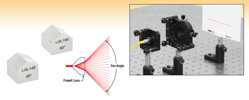
- Generate Laser Lines with Nearly Flat-Top Profiles
- 30°, 45°, 60°, or 75° Fan Angle at 633 nm
- Designed for Ø0.8 mm (1/e2) Input Beams
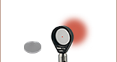
Application Idea
An LGL145 Powell Lens projecting a uniform line.
See the Application tab for more details.
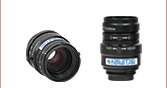
LGL145
45° Fan Angle
LGL160
60° Fan Angle


Please Wait
Click to Enlarge
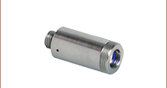
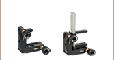
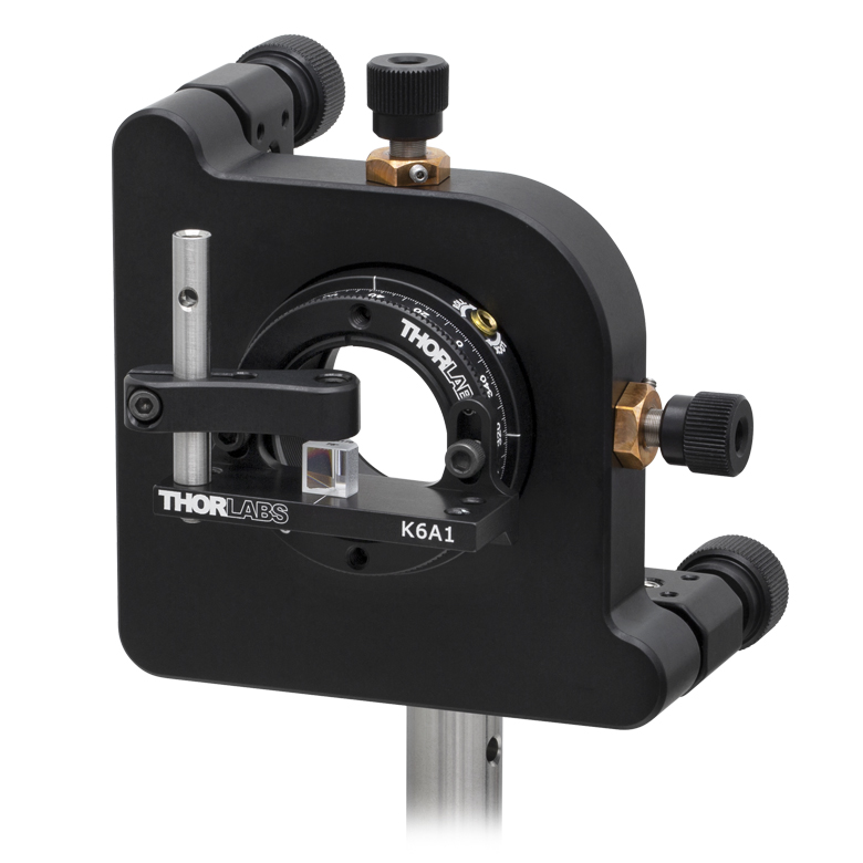
A Powell Lens Mounted on a K6XS 6-Axis Kinematic Mount Using the K6A1 Prism Mount Accessory
Click to Enlarge
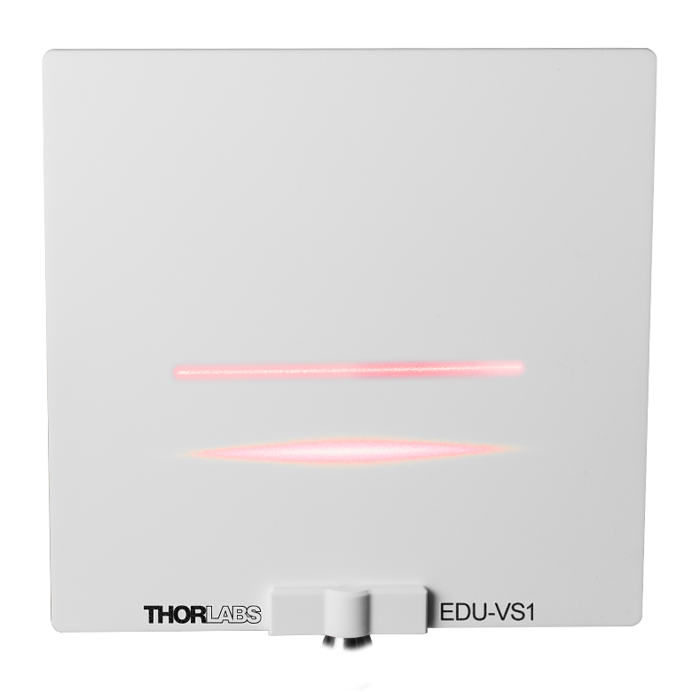
Uniform Laser Line Produced by a Powell Lens (Top) and Gaussian Laser Line Produced by a Cylindrical Lens (Bottom)
Features
- Designed for Ø0.8 mm (1/e2) Collimated Input Beams with Gaussian Intensity Distributions
- Divergence Fan Angle at 633 nm: 30°, 45°, 60°, or 75°
- Line Intensity Variation Less Than 30% for 633 nm Input (See Specs Tab for Details)
- Antireflection (AR) Coated for 400 nm to 700 nm
Powell Lenses, also known as laser line generating lenses, create straight, uniform laser lines by fanning out collimated beams in one dimension. The apex of each lens below features an acylindric curve that evenly redistributes the optical power of a Ø0.8 mm (1/e2), 633 nm gaussian input beam into a projected line with less than 30% intensity variation over the line's central 80% (see the Specs tab for typical performance graphs). This can be contrasted with standard cylindrical lenses, which produce diverging laser lines with Gaussian intensity profiles, as seen in the image to the right. Fan angles of 30°, 45°, 60°, or 75° are available.
To achieve the Ø0.8 mm 1/e2 input beam diameter using a fiber-coupled light source, we recommend our F230FC-B or F230SMA-B 633 nm fixed-focus collimation package. Inputs with other wavelengths or beam diameters may cause nominal variance in the performance of the lens.
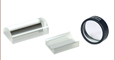
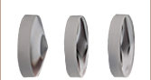
Each laser line generator lens is produced from N-SF6 glass and has a square output face. Using a form factor based on a cube, rather than a cylinder, provides a reference surface when aligning the output laser line. An antireflection (AR) coating applied to the roof and square output face provides <2% average reflectance per surface from 400 nm to 700 nm.
Mounting Options
These lenses can be mounted in a variety of ways, depending on the accuracy required for the application. For situations that require a small footprint, the PCM post clamp mount can be used in conjunction with the PCMP flat base adapter to place the Powell lens on the end of a Ø1/2" optical post. The KM100C and KM100CL adjustable kinematic mounts can add tip-tilt actuation that assists in pointing the input beam directly at the center of the Powell lens. When using either the KM100C or KM100CL mounts, be sure to mount the lens such that the fan opens parallel to the mounting clamps to avoid beam clipping. For maximum directional control, the K6XS 6-axis locking kinematic mount can be used with a K6A1 prism mounting accessory, as shown above. With their small size and square cross-section, our Powell lenses are also suitable for glue-in-place OEM applications. For more information on the importance of proper alignment when using a Powell lens, see the Application tab.
| Item # | LGL130 | LGL145 | LGL160 | LGL175 |
|---|---|---|---|---|
| Fan Anglea |
30° | 45° | 60° | 75° |
| Fan Angle Tolerancea |
+3° / -0.5° | +3° / -0.5° | +4° / -0.5° | +4.5° / -1.0° |
| Typical Fan Angle Intensity Profilea (Click for Graph) |
Raw Data |
Raw Data |
Raw Data |
Raw Data |
| Input Beam Diameter (1/e2) | 0.8 mm | |||
| Line Uniformitya,b,c | <30% Variation | |||
| Line Straightnessa,b | <0.1% | |||
| Contained Powera,d | 80% ± 5% | |||
| Clear Aperturee | >Ø4.0 mm | |||
| Substrate Material | N-SF6 | |||
| AR Coating Material |
Magnesium Fluoride (MgF2) | |||
| AR Coating Average Reflectance (Click for Graph) |
<2% per Surface (400 - 700 nm) Click Here for Raw Data from 200 - 2500 nm |
|||
| Surface Quality (Scratch-Dig) |
60-40 | |||
Powell Lens Diagram
| Dimension | Length | Tolerance |
|---|---|---|
| A | 5.9 mm | +0.00 / -0.50 mm |
| B | 6.3 mm | +0.00 / -0.20 mm |
| C | 6.3 mm | +0.00 / -0.15 mm |
Click to Enlarge Aligning a Powell lens correctly creates a laser line with a flat top beam intensity.
Creating a Uniform Laser Line
A Powell lens can be a fast and effective method to create a laser line with a flat-top profile, useful in applications such as machine vision and optical inspection. Each lens is designed for a Gaussian input beam with a specific 1/e2 diameter (0.8 mm for the lenses below). Overfilling the lens will cause the ends of the laser line to become more intense compared to the center. Conversely, underfilling the lens will cause the laser line to appear more Gaussian, with ends less intense than the laser line's center. Furthermore, the specified fan angle, uniformity, and straightness produced by the lenses below were tested at 633 nm (see the Specs tab for details) and may vary at other wavelengths.
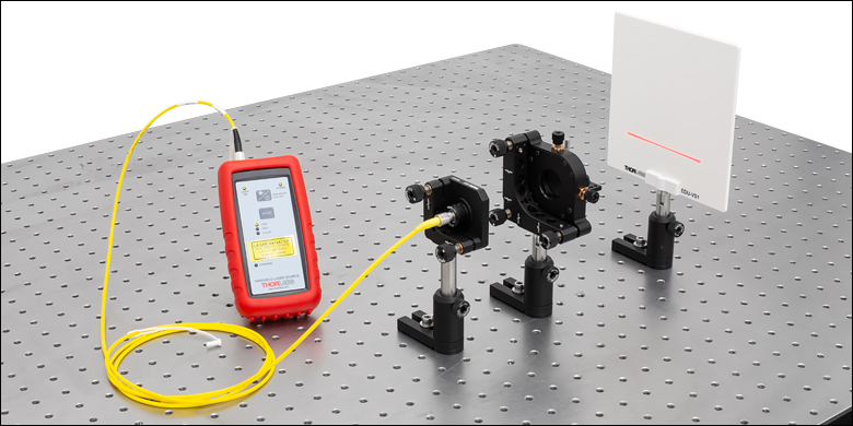
Care must be taken to properly center and align the incident beam in order to achieve the specified performance. If the input beam is centered on the roof of the prism but off angle, the resulting projection will exhibit linear coma that results in more intensity on one side of the laser line than the other.
The image to the right shows an LGL145 Powel lens mounted on a K6XS 6-axis kinematic mount. The mount has been oriented to prevent clipping the 45° fanned beam. The input beam is generated by an HLS635 handheld laser source coupled to an F230FC-B fiber collimator through a P1-630AR-2 fiber patch cable. This collimates the 635 nm light to a Ø0.8 mm beam. The K6XS 6-axis kinematic mount allows of the Powell lens alignment to be adjusted so that the beam is centered on the lens' roof and perpendicular to the output face, resulting in a uniform, straight flat-top line.
| Posted Comments: | |
Eliott Beraud
(posted 2024-06-21 12:10:15.35) Hi,
Is it possible to have an special AR coating @1366nm on these lenses ?
Thank you kindly,
Eliott Beraud jdelia
(posted 2024-06-27 03:24:49.0) Thank you for contacting Thorlabs. I have contacted you directly via email to discuss the feasibility of this customized item request. Lee Weller
(posted 2023-02-14 12:15:16.507) Would it be possible to get an idea of damage threshold for these Powell lenses? Also do you do larger ones for say 1/e2 5~mm for 532nm and fan angles similar to the ones on offer? jdelia
(posted 2023-02-16 01:28:59.0) Thank you for contacting Thorlabs. We unfortunately have not measured an exact damage threshold for these optics. However, I have reached out to you directly to discuss the specs of your beam and whether these lenses would be suitable, as well as the feasibility of your custom request. 永 周
(posted 2021-10-12 10:24:31.217) Is there a detailed value for the centerline resolution distance of one-dimensional laser line about LGL130 and LGL160? I need to use a lens to reduce this parameter to an appropriate value azandani
(posted 2021-10-28 02:28:28.0) Hello, thank you for contacting Thorlabs. We have reached out directly to gain clarification and discuss your application a bit more, but we have not heard back. If you have any further questions, please email your local Thorlabs Tech Support team directly (in your case, techsupport-cn@thorlabs.com). jongYeon Kim
(posted 2021-05-17 16:06:13.75) 1. What happens to the specs change when using a 405nm wavelength laser?
2. When using a laser with a wavelength of 405nm, where is the focus point inside the powell lens? cdolbashian
(posted 2021-06-04 11:04:18.0) Thank you for reaching out to us with your inquiries. As the index of refraction of the substrate will change as a function of wavelength, the location of the focal point internally will shift toward the -z direction (towards the source), resulting in a different fan angle. I have reached out to you directly to discuss this further. Joseph Buck
(posted 2020-07-02 12:00:55.657) Are you able to get these designed for a larger diameter beam (3 or 4 mm)? Also, what about smaller fan angles (5 & 10 degrees)? YLohia
(posted 2020-07-02 02:18:27.0) Hello Joseph, thank you for contacting Thorlabs. Custom optics can be requested by emailing techsupport@thorlabs.com. We will reach out to you directly to discuss the possibility of offering this. |